Immer. Sicher. Dicht.
|
|
|
- Tomasz Michalik
- 7 lat temu
- Przeglądów:
Transkrypt
1 Immer. Sicher. Dicht. Montageanweisung HSD-SSG für neu zu verlegende bzw. bereits verlegte Rohre Installation Instruction HSD-SSG for pipes to be newly laid or that have been already laid Instructions d installation HSD-SSG pour tube à reposer ou déjà installé Montage-instructie HSD-SSG voor nieuw te installeren resp. al geïnstalleerde buizen Instrukcja montażu HSD-SSG dla nowo instalowanych oraz uprzednio ułożonych rur DE GB FR NL PL HSD 100-SSG SL, HSD 100-SSG HSD 150-SSG SL, HSD 150-SSG , HSD 200-SSG SL, HSD 200-SSG , HSD 250-SSG SL, HSD 300-SSG SL


2 - 1-1 HSD 100-SSG - HSD 300-SSG 1 2a D D b 3a 3b 10 mm 2


3 3c 3d
4 Notizen / Notes / Remarques / Opmerkingen / Notatki 4
5 Inhalt 1 Allgemeines und Verwendungszweck 2 Allgemeine Hinweise 3 Sicherheitshinweise 4 Beschreibung 5 Lieferumfang DE 6 Benötigtes Werkzeug und Hilfsmittel 7.1 Montage von Gebäudeaußenseite 7.2 Montage bei bereits verlegten Rohren (bei HSD 150/200/250 und 300-SSG) 7.3 Montage von Gebäudeinnenseite 1 Allgemeines und Verwendungszweck Die Kabel- und Rohrdichtungen P-PIPE Basic HSD 100-SSG sind zur Montage und Einführung von 1 Kabel/Rohr mit Außendurchmesser mm oder mm, bei HSD 150-SSG von mm oder mm, bei HSD 200-SSG von mm oder mm, bei HSD 250-SSG von mm und bei HSD 300-SSG von mm geeignet. 2 Allgemeine Hinweise Bei einseitiger Montage der Kabel- und Rohrdichtung in Kernbohrungen, ist die Abdichtung auf der Gebäudeaußenseite vorzunehmen. Bei korrekter Montage ist ein Nachziehen der Schrauben nicht notwendig. Kabel- und Rohrdichtungen sind keine Festpunkte oder Lager und können somit keine mechanischen Kräfte aufnehmen. Zu erwartende Senkungen müssen durch den Einbau von Zentrierhilfen bzw. Abstandshaltern in den Futterrohren oder Kernbohrungen aufgefangen werden. Weiteres Zubehör und Informationen unter und in den technischen Datenblättern. 3 Sicherheitshinweise Schützen Sie die Kabel- und Rohrdichtungen bei der Montage vor Beschädigungen, Feuchte und Verunreinigungen. Überprüfen Sie die Lieferung auf Vollständigkeit und alle Einzelteile auf eventuelle Schäden. Es dürfen nur unbeschädigte Teile montiert werden. Bei der Installation der Kabel- und Rohrdichtungen müssen die entsprechenden Vorschriften der Berufsgenossenschaften, die VDE-Bestimmungen, die entsprechenden nationalen Sicherheits- und Unfallverhütungsvorschriften sowie die Richtlinien (Arbeits- und Verfahrensanweisungen) Ihres Unternehmens beachtet werden. Für die Reinigung der Kabel- und Rohrdichtungen dürfen keine lösungsmittelhaltigen Reiniger verwendet werden! Wir empfehlen Kabelreiniger M.T.. 5
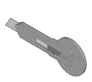
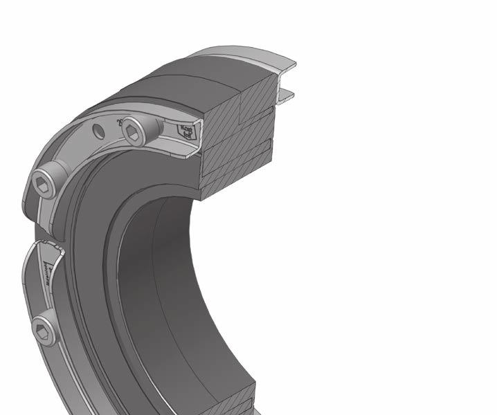
6 DE 4 Beschreibung (Bsp.: HSD 200-SSG ) Blinddeckel integrierte Drehmomentkontrolle (Kontrollöffnung) Gummipressring Innensechskantschraube Edelstahl- U-Profil 5 Lieferumfang Zum Lieferumfang der Kabel- und Rohrdichtungen HSD 100-SSG, HSD 150-SSG, HSD 200-SSG, HSD 250-SSG und HSD 300-SSG gehören: Bezeichnung inklusive Blinddeckel bzw. Blindstopfen Blinddeckel Zubehör * *Blinddeckel als Zubehör optional erhältlich HSD 100-SSG SL HSD 100-SSG HSD 150-SSG SL HSD 150-SSG HSD 200-SSG HSD 200-SSG HSD 250-SSG SL HSD 300-SSG SL 6 Benötigtes Werkzeug und Hilfsmittel Für die ordnungsgemäße Installation der Kabel- und Rohrdichtungen HSD 100-SSG bzw. HSD 150-SSG, HSD 200-SSG, HSD 250-SSG und HSD 300-SSG benötigen Sie neben dem üblichen Standardwerkzeug die folgenden Werkzeuge und Hilfsmittel: Montageset HSI150-DG bestehend aus: 1 Drehmomentschlüssel 4-20 Nm, 1/4 Zoll 1 Verlängerung 100 mm, 1/4 Zoll 2 Verlängerungen 150 mm, 1/4 Zoll 1 Aufnahme für Akkuschrauber, Vierkant, 1/4 Zoll 1 Steckschlüsseleinsatz M6, SW 5, 1/4 Zoll 1 Steckschlüsseleinsatz M6, 100 mm lang mit Kugelkopf, 1/4 Zoll Legende 1 Gleitmittel 1 Cuttermesser 1 Putztuch 1 Arbeitsschritte zu beachtende Hinweise 6
7 DE 7.1 Montage von Gebäudeaußenseite 1 2a 2b Kernbohrung/Futterrohr und Kabel- oder Rohrleitung reinigen. Eventuell vorhandene Ausbrüche und/oder Lunkerstellen egalisieren. Überprüfen der Durchmesser von Kernbohrung/Futterrohr und +2 Medienleitung. Toleranz D -1 mm sowie Außen- bzw. Bohrungsmaß der Rohrdichtung. Innenseite Futterrohr muss sauber, trocken und fettfrei sein! Der jeweilige Anwendungsbereich ist auf der Innenseite der Kabel-oder Rohrdichtung angegeben. Blinddeckel aus der Kabel- und Rohrdichtung HSD 150-SSG , HSD150-SSG SL sowie HSD 200-SSG und HSD 200-SSG SL entfernen. Blindstopfen bei HSD100-SSG SL und HSD 100-SSG umklappen und herausreißen. 7.2 Montage bei bereits verlegten Rohren (bei HSD 150/200/250 und 300-SSG) 3a 3b Zum Teilen der Kabel- und Rohrdichtung eine Schraube am Teilungsschnitt lösen und entfernen. Bei HSD 150-SSG und HSD 200-SSG vorderes und hinteres Presssegment aufklappen und in ca. 10 mm Abstand zur Schraubenbohrung mit einem scharfen Messer den Gummipressring durchtrennen. Vordere und hintere Presssegmente müssen versetzt angeordnet sein. 3c Danach einzeln die Segmentringe umklappen und abreißen bis der benötigte Durchmesserbereich auf dem Segment sichtbar ist. Dieser Schritt muss bei geteilten Dichtungen an der anderen Ringraumdichtungshälfte identisch wiederholt werden; die Anzahl der entfernten Segmente muss an beiden Ringraumdichtungshälften übereinstimmen. Segmentringe bei Bedarf mit scharfem Messer an der Trennstelle einschneiden und anschließend abreißen. 3d 4 Gummipressring am Teilungsschnitt mit Gleitmittel (nicht im Lieferumfang) einschmieren. Kabel- oder Rohrleitung mit Gleitmittel einschmieren, in Kabel- und Rohrdichtung einführen bzw. die Dichtung über die Medienleitung klappen und von der Gebäudeaußenseite in Kernbohrung/ Futterrohr wandbündig einsetzen. Nicht die Außendichtfläche der Rohrdichtung einschmieren. 5 Innensechskantschrauben kreuzweise anziehen bis Drehmoment erreicht ist (siehe Tabelle) und der Gummi aus allen Kontrollöffnungen gleichmäßig heraustritt. 7
8 DE Tabelle Bezeichnung Kernbohrung/ Futterrohr +2-1 (mm) Ø i Anzahl der Bohrungen Kabel-/Rohr Ø a (mm) Anzugsmoment (Nm) HSD 100-SSG SL HSD 100-SSG , 32, 40, 50, 63 8 HSD 150-SSG SL HSD 150-SSG , 90, HSD 200-SSG SL HSD 200-SSG , 125, 135, HSD 250-SSG SL HSD 300-SSG SL Optische Kontrolle: Die Kabel- und Rohrdichtung ist gleichmäßig verpresst, sobald der Gummi in allen Kontrollöffnungen sicht- und fühlbar ist (siehe Detail). 7.3 Montage von Gebäudeinnenseite 6 Verfahren wie bei Montage von Gebäudeaußenseite Pos. 1-3, jedoch Montage von der Gebäudeinnenseite. Kabel- oder Rohrleitung mit Gleitmittel einschmieren, in Kabel- und Rohrdichtung einführen bzw. die Dichtung über die Medienleitung klappen und von Gebäudeinnenseite bis zur Außenkante von Kernbohrung/Futterrohr schieben. Anschließend Innensechskantschrauben mit Verlängerung kreuzweise anziehen bis Drehmoment erreicht ist (siehe Tabelle) und der Gummi aus allen Kontrollöffnungen gleichmäßig heraustritt. Nicht die Außendichtfläche der Rohrdichtung einschmieren. Unsere Produkte sind entsprechend ihrer vorgesehenen Verwendungsweise ausschließlich für den Einbau in Bauwerke entwickelt, deren Baustoffe dem derzeitigen Stand der Technik entsprechen. Für eine andere oder darüber hinaus gehende Verwendung, sofern sie nach Rücksprache mit uns nicht ausdrücklich schriftlich bestätigt wurde, übernehmen wir keine Haftung. Service-Telefon Änderungen vorbehalten! 8
9 Contents 1 General information and intended use 2 General information 3 Safety instructions 4 Description 5 Scope of delivery EN 6 Required tools and aids 7.1 Installation from outside of building 7.2 IInstallation where pipes have already been installed (HSD 150/200/250 and 300-SSG) 7.3 Installation from inside of building 1 General information and intended use The P-PIPE Basic HSD 100-SSG cable and pipe seals are suitable for the installation and insertion of 1 cable/pipe with outer diameter mm or mm, mm or mm for HSD 150-SSG, mm or mm for HSD 200-SSG, mm for HSD 250-SSG and mm for HSD 300-SSG. 2 General information For one-sided installation of the cable and pipe seal into core drillings, seal from outside of building. If installation is carried out correctly, it will not be necessary to retighten the screws. Cable and pipe seals are not fixed points or bearings and therefore cannot absorb any mechanical forces. Any anticipated reductions must be compensated for by the installation of centering guides and/or spacers in the conduits or core drillings. Further accessories and information at and in the technical data sheets. 3 Safety instructions Protect the cable and pipe seals from damage, moisture and impurities during installation. Check that all necessary components have been delivered and that they are not damaged. You must not install damaged components. Cable and pipe seal installation must comply with the relevant professional association regulations, VDE provisions, national safety and accident prevention regulations as well as company regulations (work and procedural instructions). Do not use solvent-based cleaning agents to clean the cable/pipe seals! We recommend using M.T.. cable cleaner. 9
10 EN 4 Description (e.g.: HSD 200-SSG ) blind plug Allen screw Rubber press ring Stainless steel u-profile Integrated torque control (inspection opening) 5 Scope of delivery The scope of delivery of the HSD 100-SSG, HSD 150-SSG, HSD 200-SSG, HSD 250-SSG and HSD 300-SSG cable and pipe seals includes: Designation blind plug included blind plug as accessory * HSD 100-SSG SL *blind plug is available as an optional accessory HSD 100-SSG HSD 150-SSG SL HSD 150-SSG HSD 200-SSG SL HSD 200-SSG HSD 250-SSG SL HSD 300-SSG SL 6 Required tools and aids To install the HSD 100-SSG or HSD 150-SSG, HSD 200-SSG, HSD 250-SSG and HSD 300-SSG cable and pipe seals correctly, you will need the following tools and aids in addition to the usual tools: HSI150-DG assembly kit, consisting of: 1 torque spanner 4-20 Nm, 1/4 inch mm extension, 1/4 inch mm extensions, 1/4 inch 1 adapter for cordless screwdriver, square, 1/4 inch 1 M6 socket, wrench size 5, 1/4 inch 1 M6 socket, 100 mm long with spherical head, 1/4 inch Legend 1 lubricant 1 cutter knife 1 cleaning cloth 1 Workflow Important information 10
11 EN 7.1 Installation from outside of building 1 Clean the core drilling/conduit and the cable or pipe. Level out any chips and/or voids which may +2 be present. Check the diameter of the core drilling/conduit and media line, tolerance D -1 mm as well as outer or drilling dimension of the pipe seal. Please make sure that the inside of the liner is clean, dry and free of grease! The respective application range is specified on the inside of the press seal. 2a Remove the blind system cover from the HSD 150-SSG , HSD150-SSG SL and HSD 200-SSG and HSD 200-SSG SL cable and pipe seal. 2b 7.2 Installation where pipes have already been installed (HSD 150/200/250 and 300-SSG) 3a Fold out and pull out the blind plug on the HSD100-SSG SL and HSD 100-SSG To split the cable and pipe seal, loosen and remove a screw on the division cut. 3b For the HSD 150-SSG and HSD 200-SSG , fold out the front and rear press segment and at a distance of approx. 10 mm from the screw drilling, separate the rubber press ring with a sharp knife. The front and rear press segments must be arranged offset. 3c Then fold out and pull off the segment rings one by one until the necessary diameter area is visible on the segment. For split seals, this step must be repeated for the other half of the press seal in exactly the same way (the same number of segments must be removed on each half of the press seal). If necessary, cut the segment rings with a sharp knife at the sectioning point and then pull off. 3d 4 Lubricate the rubber press ring on the division cut with lubricant (not included in the scope of delivery). Lubricate the cable or pipe with lubricant and insert into cable and pipe seal or fold the seal over the media line and insert into core drilling/conduit from outside of building until flush with the wall. Do not lubricate the outer sealing surface of the pipe seal. 5 Tighten the allen screws in a crosswise sequence until the torque is reached (see Table) and the rubber emerges evenly from all inspection openings. 11
12 EN Table Designation Core drilling/ Number of +2 conduit Ø i -1 (mm) drill holes Cable/pipe Ø a (mm) Tightening torque Nm) HSD 100-SSG SL HSD 100-SSG , 32, 40, 50, 63 8 HSD 150-SSG SL HSD 150-SSG , 90, HSD 200-SSG SL HSD 200-SSG , 125, 135, HSD 250-SSG SL HSD 300-SSG SL Optical inspection: The cable and pipe seal is evenly sealed as the rubber can be seen and felt in all inspection openings (see detail). 7.3 Installation from inside of building 6 Proceed as for assembly from outside of building steps 1 to 3, but mounting from inside of building. Lubricate the cable or pipe with lubricant and insert into the seal or fold the seal over the media line and insert from inside of building as far as the outer edge of the core drilling/conduit. Finally, tighten the allen screws with an extension in a crosswise sequence until the torque is reached (see Table) and the rubber emerges evenly from all inspection openings. Do not lubricate the outer sealing surface of the pipe seal. As indicated in the instructions for use, our products have been designed exclusively for installation in buildings made from state-of-the-art construction materials. We do not accept liability for use deviating from or beyond this unless our express written confirmation has been obtained in advance. Service phone Subject to change! 12
13 Sommaire 1 Information général et utilisation prévue 2 Remarques générales 3 Instructions de sécurité 4 Description 5 Contenu de la livraison 6 Outils et auxiliaires requis FR 6 Outils et auxiliaires requis 7.1 Montage de l extérieur du bâtiment 7.2 Montage sur les tubes déjà posés (sur HSD 150/200/250 et 300-SSG) 7.3 Montage du côté intérieur du bâtiment 1 Information général et utilisation prévue Les joints pour câbles et tubes P-PIPE Basic HSD 100-SSG conviennent au montage et l'insertion d'1 câble/ tube d'un diam tre extérieur de mm ou mm, les mod les HSD 150-SSG pour un diam tre extérieur de mm ou mm, les mod les HSD 200-SSG pour un diam tre extérieur de mm ou mm, les mod les HSD 250-SSG pour un diam tre extérieur de mm et les mod les HSD 300-SSG pour un diam tre extérieur de mm. 2 Remarques générales Lors du montage unilatéral du joint pour câbles et tubes dans les carottages, l'étanchéité de l'extérieur du bâtiment est effectuer. Lors de montage correct, il n'est pas nécessaire de resserrer les vis. Les joints pour câbles et tubes ne sont pas des points fixes ou des paliers et, par conséquent, ne peuvent pas absorber les efforts mécaniques. Les affaissements prévisibles doivent tre compensés par le montage d'aides au centrage et d'entretoises dans les gaines et les carottages. 3 Instructions de sécurité Lors des travaux de montage, protéger le joint pour câbles et tubes contre tout endommagement, l'humidité et les saletés. Vérifier l'exhaustivité de la livraison et l'absence d'endommagement sur les pi ces détachées. Seules des pi ces non endommagées doivent tre montées. Lors de l'installation des joints pour câbles et tubes, il convient de respecter les dispositions applicables des organismes professionnels, les dispositions de la VDE, les prescriptions nationales applicables en mati res de sécurité et de prévention des accidents ainsi que les directives (instructions de travail et de procédure) de votre société. Aucun produit base de solvant ne doit tre utilisé pour le nettoyage des joints pour câbles/tubes! Nous recommandons d'utiliser le produit pour câbles M.T.. de Hauff- Technik.
14 FR 4 Description (ex. : HSD 200-SSG ) Couvercle de fermeture Vis six pans creux Joint de pression en caoutchouc Profilé en U en acier inoxydable Contrôle intégré du torque (ouverture de contrôle) 5 Contenu de la livraison Font partie de la livraison des joints pour câbles et tubes HSD 100-SSG, HSD 150-SSG, HSD 200-SSG, HSD 250- SSG et HSD 300-SSG, les éléments suivants : Désignation HSD 100-SSG SL HSD 100-SSG HSD 150-SSG SL HSD 150-SSG HSD 200-SSG SL HSD 200-SSG HSD 250-SSG SL HSD 300-SSG SL Avec couvercle de fermeture ou bouchon 6 Outils et auxiliaires requis Couvercle de fermeture (accessoire) * Pour installer correctement le joint pour câbles et tubes HSD 100-SSG ou HSD 150-SSG, HSD 200-SSG, HSD 250-SSG et HSD 300-SSG, les outils et auxiliaires suivants sont nécessaires en plus des outils standard : *Couvercle de fermeture, disponible parmi les accessoires en option Kit d'assemblage HSI 150-DG se composant de : 1 clé dynamométrique 4-20 Nm, 1/4 pouce 1 extension de 100 mm, de pouce 2 extensions de 150 mm, de pouce 1 adaptateur pour visseuse accu 100 mm, pouce 1 embout de tournevis M6 T 5, pouce 1 embout 100 mm M6 avec t te arrondie hexagonale pouce Légende 1 lubrifiant 1 cutter 1 chiffon 1 Flux de travail Remarques respecter 14
15 FR 7.1 Montage de l'extérieur du bâtiment 1 2a 2b Nettoyer le carottage / la gaine et la conduite de câbles ou de tubes. Égaliser éventuellement les épidémies et / ou les évents Vérifier le diam tre du carottage / de la gaine et la conduite de fluide. +2 Tolérance D -1 mm et dimensions extérieure et de perçage du joint pour tubes. Le fourreau doit être propre, sec et sans graisse au côté intérieur! Le domaine d application correspondant est indiqué du côté intérieur du joint pour câbles ou tubes. Retirer le couvercle de fermeture du joint pour câbles et tubes HSD 150-SSG , HSD150- SSG SL ainsi que HSD 200-SSG et HSD 200-SSG SL. Ouvrir le bouchon sur HSD100-SSG SL et HSD 100-SSG et le retirer. 7.2 Montage sur les tubes déjà posés (sur HSD 150/200/250 et 300-SSG) 3a 3b Pour diviser le joint pour câbles et tubes, desserrer et retirer une vis au niveau de la découpe de division. Sur HSD 150-SSG et HSD 200-SSG , ouvrir les segments de pression avant et arri re et sectionner le joint de pression en caoutchouc avec un couteau tranchant une distance d'environ 10 mm de l'orifice fileté. Les segments de pression avant et arri re doivent tre agencés en quinconce. 3c Ensuite, ouvrir un un les anneaux segments et les arracher jusqu' ce que le diam tre requis soit visible sur le segment. Pour les joints séparés, répéter cette étape l'identique sur l'autre moitié du joint annulaire. Le nombre de segments sectionnés doit tre le m me pour tous les segments de joint annulaire. Enfin, entailler l'anneau segments au niveau du point de sectionnement avec un couteau tranchant et l'arracher. 3d 4 Lubrifier le joint de pression en caoutchouc sur la découpe de division avec du lubrifiant (non compris dans la livraison). Enduire la conduite de câbles ou de tubes avec du lubrifiant, l'insérer dans le joint pour câbles et tubes ou passer le joint sur la conduite de fluide et la poser au ras du mur du côté extérieur du bâtiment dans le carottage/la gaine. Ne pas lubrifier la surface d'étanchéité extérieure du joint pour tubes. 5 Serrer en croix les vis hexagonales creux jusqu' atteindre le couple de serrage (voir tableau) et sortir de mani re uniforme le caoutchouc de tous les orifices de contrôle. 15
16 FR Tableau Désignation Gaine/carottage Nombre de +2-1 (mm) perçages Ø i Øa (mm) du câble/tube Couple de serrage (Nm) HSD 100-SSG SL HSD 100-SSG , 32, 40, 50, 63 8 HSD 150-SSG SL HSD 150-SSG , 90, HSD 200-SSG SL HSD 200-SSG , 125, 135, HSD 250-SSG SL HSD 300-SSG SL Inspection optique : Le joint pour câbles et tubes est pressé de mani re uniforme d s que le caoutchouc est visible et palpable dans tous les orifices de contrôle (voir détail). 7.3 Montage du côté intérieur du bâtiment 6 Procéder comme décrit dans les positions 1 3, mais montage de l'intérieur du bâtiment. Lubrifier la conduite pour câbles ou tubes avec du lubrifiant, l'introduire dans le joint pour câbles et tubes ou rabattre le joint sur la conduite de fluide et la poser fleur de mur du côté intérieur du bâtiment jusqu'au bord extérieur du carottage / de la gaine. Serrer ensuite en croix les vis hexagonales creux avec l'extension jusqu' ce que le couple de serrage (voir tableau) soit atteint et que le caoutchouc dépasse uniformément de tous les orifices de contrôle. Ne pas lubrifier la surface d'étanchéité extérieure du joint pour tubes. Conformément l usage prévu, nos produits sont conçus exclusivement pour tre intégrés dans des constructions dont les matériaux sont conformes la réglementation technique en vigueur. Nous déclinons toutes responsabilités dans le cas d une utilisation non-conforme pour l usage indiqué si nous n avons pas donné notre accord par écrit apr s consultation. Téléphone SAV Sous réserve de modifications! 16
17 Inhoud 1 Algemene informatie en beoogd gebruik 2 Algemene aanwijzingen 3 Veiligheids instructies 4 Beschrijving 5 Leveringsomvang NL 6 Benodigd gereedschap en hulpmiddelen 7.1 Montage vanaf de buitenkant van het gebouw 7.2 Montage bij al geïnstalleerde buizen (bij HSD 150/200/250 en 300-SSG) 7.3 Montage vanaf de binnenkant van het gebouw 1 Algemene informatie en beoogd gebruik De kabel- en buisdichtingen P-PIPE Basic HSD 100-SSG zijn geschikt voor de montage en invoer van 1 kabel/buis met buiten diameter mm of mm, bij HSD 150-SSG van mm of mm, bij HSD 200-SSG van mm of mm, bij HSD 250-SSG van mm en bij HSD 300-SSG van mm. 2 Algemene aanwijzingen Bij eenzijdige montage van de kabel- en buisdichting in kernboringen, moet de afdichting aan de buitenkant van het gebouw worden uitgevoerd. Bij een correcte montage is natrekken van de bouten niet nodig. Kabel- en buisdichtingen zijn geen vaste punten of lagers en kunnen geen mechanische krachten opnemen. Te verwachten verlagingen moeten door de inbouw van centreerhulpmiddelen resp. afstandhouders in de doorvoerbuizen of kernboringen worden opgevangen. Andere toebehoren en informatie onder en in de technische specificatiebladen. 3 Veiligheids instructies Bescherm de kabel- en buisafdichtingen bij de montage-installatie tegen beschadigingen, vocht en verontreiniging. Controleer de levering op volledigheid en alle losse onderdelen op eventuele schade. Er mogen alleen onbeschadigde delen worden gemonteerd. Bij de installatie van de kabel- en buisafdichtingen moeten de geldende voorschriften van de bedrijfsverenigingen, de VDE-bepalingen, de geldende nationale veiligheids- en ongevallenpreventievoorschriften en de richtlijnen (werk- en procedure-instructies) van uw onderneming worden aangehouden. Voor het reinigen van de kabel- en buisdichtingen mogen geen oplosmiddelhoudende middelen worden gebruikt! Wij adviseren kabelreiniger M.T.. 17
18 NL 4 Beschrijving (voorbeeld: HSD 200-SSG ) Blinddeksel Inbusbout Rubber aandrukring Roestvrij staal U-profiel Geîntegreerde draaimoment controle (controleopening) 5 Leveringsomvang Tot de leveringsomvang van de kabel- en buisdichtingen HSD 100-SSG, HSD 150-SSG, HSD 200-SSG, HSD 250- SSG en HSD 300-SSG behoren: Benaming inclusief blinddeksel resp. blindstoppen Blinddeksel toebehoren * *Blinddeksel als optionele toebehoren leverbaar HSD 100-SSG SL HSD 100-SSG HSD 150-SSG SL HSD 150-SSG HSD 200-SSG SL HSD 200-SSG HSD 250-SSG SL HSD 300-SSG SL 6 Benodigd gereedschap en hulpmiddelen Voor de correcte installatie van de kabel- en buisdichtingen HSD 100-SSG resp. HSD 150-SSG, HSD 200-SSG, HSD 250-SSG en HSD 300-SSG heeft u naast het standaard gereedschap ook de volgende gereedschappen en hulpmiddelen nodig: Opstel set HSI150-DG bestaande uit: 1 draaimomentsleutel 4-20 Nm, 1/4 1 verlenging 100 mm, 1/4 2 verlengingen 150 mm, 1/4 1 houder voor akku schroefmachine, vierkant, 1/4 1 steeksleutelbit M6, SW 5, 1/4 1 steeksleutelbit M6, 100 mm lang met kogelkop, 1/4 Legenda 1 glijmiddel 1 cuttermes 1 poetsdoek 1 Werk stroom aan te houden instructies 18
19 NL 7.1 Montage vanaf de buitenkant van het gebouw 1 Kernboring/doorvoerbuis en kabel- of buisleiding reinigen. Eventueel aanwezige gaten en/of oneffenheden egaliseren. Controleer de doorsnede van de kernboring/doorvoerbuis en mediumleiding. +2 Tolerantie D -1 mm en buiten- resp. boringsmaat van de buisdichting. De binnenzijde van de doorvoerbuis moet schoon, droog en vetvrij. Het betreffende toepassingsgebied is op de binnenkant van de drukdichting aangegeven. 2a 2b Verwijder het blinddeksel uit de kabel- en buisdichting HSD 150-SSG , HSD150-SSG SL en de HSD 200-SSG en HSD 200-SSG SL. Blindstop bij HSD100-SSG SL en HSD 100-SSG omklappen en uitscheuren. 7.2 Montage bij al geïnstalleerde buizen (bij HSD 150/200/250 en 300-SSG) 3a 3b Maak voor het delen van de kabel- en buisdichting een schroef op de deling los en verwijder deze. Klap bij HSD 150-SSG HSD 200-SSG het voorste en achterste druksegment open en snijdt op ca. 10 mm afstand t.o.v. het schroefgat met een scherp mes de rubber aandrukring door. De voorste en achterste aandruksegmenten moeten versprongen worden gepositioneerd. 3c Daarna de segmentringen afzonderlijk omklappen en afscheuren tot het benodigde doorsnedebereik op het segment zichtbaar is. Deze stap moet bij gedeelde dichtingen aan de andere helft van de ringruimtedichting identiek worden herhaald; het aantal verwijderde segmenten moet aan beide helften van de ringruimtedichting gelijk zijn. Segmentringen indien nodig met een scherp mes op de scheidingsplaat insnijden en daarna afscheuren. 3d 4 Rubber aandrukring op deelsnede met glijmiddel (niet meegeleverd) insmeren. Kabel- of buisleiding met glijmiddel insmeren, in de kabel- en buisdichting plaatsen resp. de dichting over de mediumleiding klappen en vanaf de buitenkant van het gebouw in de boring/doorvoerbuis gelijk met de wand positioneren. Smeer het buiten afdichtoppervlak van de buisdichting niet in. 5 De inbusschroeven kruisgewijs aantrekken tot het draaimoment is bereikt (zie tabel) en het rubber uit alle controle-openingen gelijkmatig uitloopt. 19
20 NL Tabel Benaming Kernboring/ doorvoerbuis +2-1 (mm) Ø i Aantal van de boringen Kabel-/buis Ø a (mm) Aantrekmoment (Nm) HSD 100-SSG SL HSD 100-SSG , 32, 40, 50, 63 8 HSD 150-SSG SL HSD 150-SSG , 90, HSD 200-SSG SL HSD 200-SSG , 125, 135, HSD 250-SSG SL HSD 300-SSG SL Optische controle: De kabel- en buisdichting is gelijkmatig aangedrukt, zodra het rubber in alle controleopeningen zichtbaar en voelbaar is (zie detail). 7.3 Montage vanaf de binnenkant van het gebouw 6 Methode als bij de montage vanaf de buitenkant van een gebouw pos. 1-3, maar montage vanaf de binnenkant van een gebouw. Smeer de kabel- of buisleiding in met glijmiddel, plaats deze in de kabel- en buisdichting of klap de dichting over de mediumleiding en positioneer deze vanaf de binnenkant van het gebouw tot aan de buitenkant van de kernboring/doorvoerbuis. Daarna de inbusschroeven met verlenging kruisgewijs aantrekken tot het draaimoment is bereikt (zie tabel) en het rubber uit alle controle-openingen gelijkmatig uitloopt. Smeer het buiten afdichtoppervlak van de buisdichting niet in. Onze producten zijn uitsluitend bedoeld voor gebruik conform inbouw in bouwwerken ontwikkeld, waarvan de materialen aan de huidige stand van de techniek voldoen.voor een andere toepassing dan wel ander gebruik, voor zover dit na overleg met ons niet uitdrukkelijk schriftelijk is bevestigd, aanvaarden wij geen aansprakelijkheid. Servicetelefoon Wijzigingen voorbehouden! 20
 7.")
21 Spis treści 1 Informacje ogólne i przeznaczenie 2 Wskazówki ogólne 3 Instrukcja bezpieczeństwa 4 Opis 5 Zakres dostawy PL 6 Niezbędne narzędzia i środki pomocnicze 7.1 Montaż od zewnętrznej strony budynku 7.2 Montaż na ułożonych wcześniej rurach (w przypadku HSD 150/200/250 i 300-SSG) 7.3 Niezbędne narzędzia i środki pomocnicze 1 Informacje ogólne i przeznaczenie Wkłady uszczelniające do kabli i rur P-PIPE Basic przeznaczone są do montażu i wprowadzania 1 kabla/ rury o średnicy zewnętrznej: w przypadku HSD 100-SSG mm lub mm, w przypadku HSD 150- SSG mm lub mm, w przypadku HSD 200-SSG mm lub mm, w przypadku HSD 250-SSG mm, a w przypadku HSD 300-SSG mm. 2 Wskazówki ogólne W przypadku jednostronnego montażu wkładu uszczelniającego do kabli i rur w przewiertach uszczelnienie należy wykonać po zewnętrznej stronie budynku. Przy prawidłowym montażu nie ma potrzeby ponownego dokręcania śrub. Wkłady uszczelniające do kabli i rur nie są punktami stałymi ani łożyskami, dlatego też nie są odporne na działanie sił mechanicznych. Należy zapewnić niwelację ewentualnych obciążeń poprzez montaż elementów centrujących lub przekładek w rurach przepustowych lub przewiertach. Opis pozostałych elementów wyposażenia dodatkowego oraz szczegółowe informacje podane są na stronie internetowej oraz w arkuszach danych technicznych. 3 Instrukcja bezpieczeństwa Podczas montażu wkład uszczelniający do kabli i rur należy chronić przed uszkodzeniami, wilgocią i zanieczyszczeniami. Sprawdzić, czy dostawa jest kompletna oraz czy poszczególne części nie są uszkodzone. Dozwolony jest montaż wyłącznie nieuszkodzonych części. Podczas montażu wkładów uszczelniających do kabli i rur należy przestrzegać odpowiednich przepisów prawa, norm branżowych, odpowiednich krajowych przepisów BHP oraz norm zakładowych (instrukcji dotyczących pracy i procedur działania). Do czyszczenia wkładów uszczelniających do kabli i rur nie wolno używać środków czyszczących zawierających rozpuszczalniki! Zalecamy używanie preparatu do czyszczenia kabli M.T.. 21

22 PL 4 Opis (przykład: HSD 200-SSG ) Pokrywa pełna Śruba imbusowa Gumowy pierścień dociskowy Ceownik ze stali nierdzewnej Zintegrowana kontrola poprawności montażu (otwór kontrolny) 5 Zakres dostawy Zakres dostawy wkładów uszczelniających do kabli i rur HSD 100-SSG, HSD 150-SSG, HSD 200-SSG, HSD 250- SSG i HSD 300-SSG obejmuje: Oznaczenie HSD 100-SSG SL HSD 100-SSG HSD 150-SSG SL HSD 150-SSG HSD 200-SSG SL HSD 200-SSG HSD 250-SSG SL HSD 300-SSG SL 6 Niezbędne narzędzia i środki pomocnicze Do prawidłowego montażu wkładów uszczelniających do kabli i rur HSD 100-SSG wzgl. HSD 150-SSG, HSD 200-SSG, HSD 250-SSG i HSD 300-SSG potrzebne są, oprócz standardowych narzędzi, następujące narzędzia i środki pomocnicze: Zestaw montażowy HSI 150-DG, w którego skład wchodzą: 1 klucz dynamometryczny 4-20 Nm, 1/4 cala 1 środek poślizgowy 1 przedłużka 100 mm, 1/4 cala 1 nóż tapicerski 2 przedłużki po 150 mm, 1/4 cala 1 ściereczka 1 uchwyt czworokątny do wkrętarki akumulatorowej, 1/4 cala 1 nasadka do klucza nasadowego M6, rozm. 5, 1/4 cala 1 nasadka do klucza nasadowego M6, długość 100 mm, z końcówką kulową, 1/4 cala Legenda Z pokrywą pełną lub zaślepką Pokrywa pełna jako osprzęt *pokrywa pełna dostępna opcjonalnie jako zamówienie dodatkowe 1 Czynności Ważne wskazówki 22
23 PL 7.1 Montaż od zewnętrznej strony budynku 1 2a 2b Oczyścić przewiert/rurę przepustową i kabel lub rurę. Wyrównać ewentualne wykruszenia i/lub wyszczerbienia. Sprawdzić średnicę przewiertu/rury przepustowej i średnicę przewodu mediów. +2 Tolerancja D -1 mm dotyczy wymiarów rury/kabla jak również uszczelnianego otworu. Wnętrze ruryprzepustowej musi być czyste, suche i wolne od tłuszczu! Określenie obszaru zastosowania podane jest na wewnętrznej stronie wkładu uszczelniającego do kabli i rur. Zdjąć pokrywę pełną z wkładu uszczelniającego do kabli i rur HSD 150-SSG , HSD150- SSG SL oraz HSD 200-SSG i HSD 200-SSG SL. W przypadku wkładów HSD100-SSG SL i HSD 100-SSG odgiąć i wyrwać zaślepkę. 7.2 Montaż na ułożonych wcześniej rurach (w przypadku HSD 150/200/250 i 300-SSG) 3a Aby rozdzielić wkład uszczelniający do kabli i rur, należy odkręcić i wyjąć śrubę znajdującą się w miejscu przecięcia. 3b W przypadku wkładów HSD 150-SSG i HSD 200-SSG rozchylić przedni oraz tylny segment dociskowy i za pomocą ostrego noża przeciąć gumowy pierścień dociskowy w odległości ok. 10 mm od otworu na śrubę. Przednie i tylne segmenty dociskowe muszą być wyrównane. 3c Następnie odgiąć i oderwać poszczególne pierścienie segmentowe, aż na segmencie widoczny będzie potrzebny zakres średnic. W przypadku dzielonych wkładów uszczelniających krok ten należy powtórzyć w ten sam sposób na drugiej połówce wkładu uszczelniającego; liczba usuniętych segmentów musi być identyczna na obu połówkach wkładu uszczelniającego. W razie potrzeby naciąć pierścienie segmentowe ostrym nożem w miejscu przedzielenia i oderwać. 3d 4 Nasmarować gumowy pierścień dociskowy w miejscu przecięcia środkiem poślizgowym (nie wchodzi w zakres dostawy). Nasmarować kabel lub rurę środkiem poślizgowym, wprowadzić we wkład uszczelniający do kabli i rur lub założyć wkład uszczelniający na przewód mediów i osadzić od zewnętrznej strony budynku w przewiercie/rurze przepustowej w taki sposób, aby znajdował się na równi ze ścianą. Nie smarować zewnętrznej powierzchni uszczelniającej wkładu uszczelniającego. 5 Dokręcać śruby imbusowe na krzyż, aż osiągnięty zostanie moment dokręcenia (patrz tabela), a guma będzie równomiernie wystawać ze wszystkich otworów kontrolnych. 23
24 PL Tabela Oznaczenie Przewiert/rura przepustowa +2-1 (mm) Ø i Liczba otworów Średnica kabla/ rury Ø a (mm) Moment dokręcenia (Nm) HSD 100-SSG SL HSD 100-SSG , 32, 40, 50, 63 8 HSD 150-SSG SL HSD 150-SSG , 90, HSD 200-SSG SL HSD 200-SSG , 125, 135, HSD 250-SSG SL HSD 300-SSG SL Kontrola wizualna: Wkład uszczelniający do kabli i rur jest prawidłowo zamontowany, jeśli we wszystkich otworach kontrolnych jednakowo widoczna i wyczuwalna jest guma (patrz rysunek szczegółowy). 7.3 Montaż od wewnętrznej strony budynku 6 Wykonać czynności identyczne jak w przypadku montażu od strony zewnętrznej (poz. 1-3), ale od strony wewnętrznej. Nasmarować kabel lub rurę środkiem poślizgowym, wprowadzić we wkład uszczelniający do kabli i rur lub założyć wkład uszczelniający na przewód mediów i wsunąć od wewnętrznej strony budynku aż do krawędzi zewnętrznej przewiertu/rury przepustowej. Następnie, korzystając z przedłużki, dokręcać na krzyż śruby imbusowe, aż osiągnięty zostanie moment dokręcenia (patrz tabela), a guma będzie równomiernie wystawać ze wszystkich otworów kontrolnych. Nie smarować zewnętrznej powierzchni uszczelniającej wkładu uszczelniającego. Nasze produkty, zgodnie z ich przeznaczeniem, zostały opracowane wyłącznie do montażu w budynkach wykonanych z materiałów budowlanych zgodnych z aktualnym stanem wiedzy technicznej. Nie ponosimy odpowiedzialności za wszelkie inne lub wykraczające poza wyżej opisane zastosowania, o ile nie zostały one przez nas w sposób wyraźny potwierdzone na piśmie. Serwis-telefon: Zastrzega się prawo do wprowadzania zmian! 24
25 Notizen / Notes / Remarques / Opmerkingen / Notatki 25
26 ma_hsd_ssg_ Hauff-Technik GmbH & Co. KG Robert-Bosch-Straße Hermaringen, GERMANY Tel Fax office@hauff-technik.de
Immer. Sicher. Dicht.
 Immer. Sicher. Dicht. Montageanweisung HRK100-SSG-1/18-65 und HRK100-SSG-4/8-30 Installation Instruction HRK100-SSG-1/18-65 and HRK100-SSG-4/8-30 Instructions de montage HRK100-SSG-1/18-65 et HRK100-SSG-4/8-30
Immer. Sicher. Dicht.
 Immer. Sicher. Dicht. Montageanweisung HRK200-SSG-1/110-162, -3/40-72 Installation Instruction HRK200-SSG-1/110-162, and -3/40-72 Instructions de montage HRK200-SSG-1/110-162, et -3/40-72 Montage-instructie
Immer. Sicher. Dicht.
 Immer. Sicher. Dicht. Montageanweisung HRK150-SSG-1/36-70, -1/70-112, -3/24-54 und -6/10-36 Installation Instruction HRK150-SSG-1/36-70, -1/70-112, -3/24-54 and -6/10-36 Instructions de montage HRK150-SSG-1/36-70,
Immer. Sicher. Dicht.
 Immer. Sicher. Dicht. Montageanweisung Kabel- und Rohrabdichtung HRD. Installation instructions HRD cable and pipe seal. Instructions d installation joint pour câbles et tubes HRD. Montage-instructies
Montageanweisung - KES-M150-KB-Set. Installation instructions - KES-M150-KB-Set. Instructions d installation - KES-M150-KB-Set
 Immer. Sicher. Dicht. Montageanweisung - KES-M150-KB-Set Zum Anschluss des Hateflex-Spiralschlauches 14150 an Kernbohrungen bzw. Futterrohre. Installation instructions - KES-M150-KB-Set For connecting
/2004 RENAULT MEGAN SCENIC I R/011. Cat. No. e20. e20*94/20*0680*00 D = 7,72kN. 1400Kg 75Kg. D (kn) = x 0, MAX kg.
 = x 0, MAX kg.") RENAULT MEGAN SCENIC I 1998-09/2004 Cat. No. R/011 e20 e20*94/20*0680*00 1400Kg 75Kg D = 7,72kN D (kn) = MAX kg x MAX kg x 0,00981 MAX kg + MAX kg PRZEKRÓJ A-A 75 min. 75 min. 30 o max. A R 14,5 max. R40
RENAULT MEGAN SCENIC I 1998-09/2004 Cat. No. R/011 e20 e20*94/20*0680*00 1400Kg 75Kg D = 7,72kN D (kn) = MAX kg x MAX kg x 0,00981 MAX kg + MAX kg PRZEKRÓJ A-A 75 min. 75 min. 30 o max. A R 14,5 max. R40
Montageanweisung HSD-SSG - Standard-Ringraumdichtung für neu zu verlegende bzw. bereits verlegte Rohre
 Immer. Sicher. Dicht. Montageanweisung HSD-SSG - Standard-Ringraumdichtung für neu zu verlegende bzw. bereits verlegte Rohre Assembly instruction HSD-SSG - Standard press seal for pipes to be newly laid
11/ RENAULT MEGANE II 3/5 d. R/030. Cat. No. e20. e20*94/20*0375*00 D = 7,56kN. 1350Kg 75Kg. D (kn) = x 0, MAX kg.
 = x 0, MAX kg.") RENULT MEGNE II 3/5 d. 11/2002 - Cat. No. R/030 e20 e20*94/20*0375*00 1350Kg 75Kg D = 7,56kN D (kn) = MX kg x MX kg x 0,00981 MX kg + MX kg PRZEKRÓJ - 75 min. 75 min. 30 o max. R 14,5 max. R40 max. 140
RENULT MEGNE II 3/5 d. 11/2002 - Cat. No. R/030 e20 e20*94/20*0375*00 1350Kg 75Kg D = 7,56kN D (kn) = MX kg x MX kg x 0,00981 MX kg + MX kg PRZEKRÓJ - 75 min. 75 min. 30 o max. R 14,5 max. R40 max. 140
Montageanweisung HSN/HSD/HSDD - Standard-Ringraumdichtung für neu zu verlegende bzw. bereits verlegte Rohre
 Immer. Sicher. Dicht. Montageanweisung HSN/HSD/HSDD - Standard-Ringraumdichtung für neu zu verlegende bzw. bereits verlegte Rohre Montageanweisung ADS - Abdichtset für gewellte Kabelschutzrohre sowie Nah-
RENAULT GRAND SCENIC II
 RENAULT GRAND SCENIC II 04.2004 - Cat. No. R/029 e20*94/20*0372*00 1350Kg 75Kg 8,02kN PRZEKRÓJ A-A 75 min. 75 min. 30 o max. A R 14,5 max. R40 max. A 140 min. 55 min. 100 max. 32 min. 30 o max. 350-420
02/02-05/ VOLKSWAGEN POLO htb. (9N) SEAT IBIZA W/022. Cat. No. E20 55R e20. 6,90 kn Kg 50 Kg
 SEAT IBIZA W/022. Cat. No. E20 55R e20. 6,90 kn Kg 50 Kg") VOLKSWAGEN POLO htb. (9N) SEAT IBIZA 02/02-05/09 05-08 at. No. W/022 e20 E20 55R-01-1045 1200 Kg 50 Kg 6,90 kn Moment skręcający dla śrub i nakrętek (8.8) Torgue settings for nuts and bolts (8.8) M8 25Nm
VOLKSWAGEN POLO htb. (9N) SEAT IBIZA 02/02-05/09 05-08 at. No. W/022 e20 E20 55R-01-1045 1200 Kg 50 Kg 6,90 kn Moment skręcający dla śrub i nakrętek (8.8) Torgue settings for nuts and bolts (8.8) M8 25Nm
Immer. Sicher. Dicht.
 Immer. Sicher. Dicht. Montageanweisung - Hauff-Mauerkragen HMK. DN110 DN200. Installation Instruction - Hauff wall collar HMK. DN110 DN200. Instructions de montage - Collerette d étanchéité Hauff HMK.
RENAULT LAGUNA com. R/018. Cat. No. e20. e20*94/20*0132*00 D = 8,50kN. 1500Kg 75Kg. D (kn) = x 0, MAX kg. MAX kg
 = x 0, MAX kg. MAX kg") RENAULT LAGUNA com. 2001 - Cat. No. R/018 e20 e20*94/20*0132*00 1500Kg 75Kg D = 8,50kN D (kn) = x x 0,00981 + PRZEKRÓJ A-A 75 min. 75 min. 30 o max. A R 14,5 max. R40 max. A 140 min. 55 min. 100 max. 32
RENAULT LAGUNA com. 2001 - Cat. No. R/018 e20 e20*94/20*0132*00 1500Kg 75Kg D = 8,50kN D (kn) = x x 0,00981 + PRZEKRÓJ A-A 75 min. 75 min. 30 o max. A R 14,5 max. R40 max. A 140 min. 55 min. 100 max. 32
Immer. Sicher. Dicht.
 Immer. Sicher. Dicht. Montageanweisung - Ringraumdichtung HRD 150/160-2SGi zur nachträglichen Montage in HSI 150. Press seal installation instructions HRD 150/160-2SGi for retrofit installation in HSI
Immer. Sicher. Dicht.
 Immer. Sicher. Dicht. Montageanweisung - Zement-Verbundrohr ZVR, Durchmesser 80-300 mm mit zementgebundener Spezialbeschichtung. Installation Instruction - Composite cement pipe ZVR, with a diameter from
Montageanweisung HSI150-DG zur nachträglichen Montage. Installation Instruction HSI150-DG for retrofitting
 Montageanweisung HSI150-DG zur nachträglichen Montage Installation Instruction HSI150-DG for retrofitting Instructions de montage HSI150-DG pour un montage ultérieur Montage-instructie HSI150-DG voor montage
PRZEKRÓJ A-A. The clearance specified in appendix VII, diagram 25a/b of Regulation No UN EU must be guaranteed at laden weight of the vehicle.
 PRZEKRÓJ - 75 min. 75 min. 30 o max. R 14,5 max. R40 max. 140 min. 55 min. 100 max. 32 min. 30 o max. 350-420 PL Należy zagwarantować przestrzeń swobodną według załącznika VII, rysunek 25a/b Regulaminu
06/ / MERCEDES C-KLASA (W-203) sed. MERCEDES C-KLASA (W-203) com. M/032. Cat. No. e20*94/20*0513*00. 10,00kN.
 sed. MERCEDES C-KLASA (W-203) com. M/032. Cat. No. e20*94/20*0513*00. 10,00kN.") MERCEDES C-KLASA (W-203) sed. MERCEDES C-KLASA (W-203) com. 06/2000-2007 04/2001-2007 Cat. No. M/032 e20*94/20*0513*00 1500Kg 75Kg 10,00kN Moment skręcający dla śrub i nakrętek (8.8) Torgue settings for
MERCEDES C-KLASA (W-203) sed. MERCEDES C-KLASA (W-203) com. 06/2000-2007 04/2001-2007 Cat. No. M/032 e20*94/20*0513*00 1500Kg 75Kg 10,00kN Moment skręcający dla śrub i nakrętek (8.8) Torgue settings for
Immer. Sicher. Dicht.
 Immer. Sicher. Dicht. Montageanweisung HSI150-DG zur nachträglichen Montage Installation Instruction HSI150-DG for retrofitting Instructions de montage HSI150-DG pour un montage ultérieur Montage-instructie
TR18 INSTALATION MANUAL / INSTRUKCJA MONTAŻU. cart for flat displays
 INSTLTION NUL / INSTRUKCJ ONTŻU cart for flat displays WRNING: Please read this manual before the installation to ensure proper assembly. The assembly should be carried out in accordance with this manual
Montageanweisung - Standard-Ringraumdichtung HRK100/ HRK150/ HRK200 mit Supersegmentringtechnik.
 Immer. Sicher. Dicht. Montageanweisung - Standard-Ringraumdichtung HRK100/ HRK150/ HRK200 mit Supersegmentringtechnik. Assembly instruction - Standard press seal HRK100/ HRK150/ HRK200 with super segmented
Abbildung Montage links Drawing for left hand installation
 300.058.xx Eck-Drehbeschlag für Möbel mit scharnierten Türen Corner swivel fitting for furniture with hinged doors Mécanisme d angle pour meubles avec portes de charnières Wyposażenie do szafek narożnych
Zwora Yale US06. Yale seria US kg. Zastosowanie. Właściwości. Parametry techniczne
 Zwora Yale US06 Yale seria US06 270 kg Zastosowanie Zwory serii US06 przeznaczone są do realizowania kontroli dostępu w pomieszczeniach wymagających podstawowej ochrony np. drzwi wewnętrzne. Właściwości
OPEL VECTRA C htb. sed.
 OPL VCTRA C htb. sed. 06/2002 - Cat. No. O/026 e20*94/20*0319*00 1950Kg 80Kg 10,72kN PRZKRÓJ A-A 75 min. 75 min. 30 o max. A R 14,5 max. R40 max. A 140 min. 55 min. 100 max. 32 min. 30 o max. 350-420 PL
Instrukcja montażu konstrukcji wolnostojącej do kolektorów płaskich
 Instrukcja montażu konstrukcji wolnostojącej do kolektorów płaskich Aluminum free-standing structure/montageanweisung der freistehenden Aluminium- Konstruktion 2m 2, 2,5m 2, 2,57m 2 02-1051 ; 02-1052;
Wyroby medyczne Systemy zarządzania jakością Wymagania do celów przepisów prawnych
 POPRAWKA do POLSKIEJ NORMY ICS 03.120.10; 11.040.01 PN-EN ISO 13485:2012/AC Wprowadza EN ISO 13485:2012/AC:2012, IDT Wyroby medyczne Systemy zarządzania jakością Wymagania do celów przepisów prawnych Poprawka
Montageanweisung HRD-SG - Standard-Ringraumdichtung. Kabeldichtung mit Segmentringen. Größen und Dimensionen.
 Immer. Sicher. Dicht. Montageanweisung HRD-SG - Standard-Ringraumdichtung. Kabeldichtung mit Segmentringen. Größen und Dimensionen. Assembly instruction HRD-SG - Standard-Press-seal. Cable seal with segment
Montageanleitung Automatische Verriegelung Assembly Instructions - Automatic Locking Instrukcja Montażu - Zamknięcie Automatyczne
 Montageanleitung Automatische Verriegelung Assembly Instructions - Automatic Locking Instrukcja Montażu - Zamknięcie Automatyczne Container & Compactor Components Übersicht Overview Orientacja Schritt
01/ KIA SPORTAGE HYUNDAY TUCSON K/020. Cat. No. e20. e20*94/20*0371*00 D = 10,30kN. 2000Kg 80Kg. D (kn) = x 0, MAX kg.
 = x 0, MAX kg.") KIA SPORTAGE HYUNDAY TUCSON 01/2005-2004 - Cat. No. K/020 e20 e20*94/20*0371*00 2000Kg 80Kg D = 10,30kN D (kn) = MAX kg x MAX kg x 0,00981 MAX kg + MAX kg PRZEKRÓJ A-A 75 min. 75 min. 30 o max. A R 14,5
KIA SPORTAGE HYUNDAY TUCSON 01/2005-2004 - Cat. No. K/020 e20 e20*94/20*0371*00 2000Kg 80Kg D = 10,30kN D (kn) = MAX kg x MAX kg x 0,00981 MAX kg + MAX kg PRZEKRÓJ A-A 75 min. 75 min. 30 o max. A R 14,5
Oprawa / Fixture WERKIN
 Oprawa / Fixture WERKIN Podstawowe elementy oprawy / Basic fixture components 3 4 5 2 1 1. profil OWERKIN / OWERKIN profile 2. zaślepka / end cap WERKIN WP 3. osłonka / cover 24140 WERKIN WL 24141 HS22
B IURO B ADAWCZE DS. J AKOŚCI
 ISO 9001 Q Ref. Certif. No. PL 2 IEC SYSTEM FOR MUTUAL RECOGNITION OF TEST CERTIFICATES FOR ELECTRICAL EQUIPMENT (IECEE) CB SCHEME SYSTEME CEI D ACCEPTATION MUTUELLE DE CERTIFICATS D ESSAIS DES EQUIPEMENTS
07/ OPEL ZAFIRA II O/034. Cat. No. e20. e20*94/20*0759*00 D = 9,60kN. 1650Kg 75Kg. D (kn) = x 0, MAX kg. MAX kg
 = x 0, MAX kg. MAX kg") OPEL ZAFIRA II 07/2005 - Cat. No. O/034 e20 e20*94/20*0759*00 1650Kg 75Kg D = 9,60kN D (kn) = MAX kg x MAX kg x 0,00981 MAX kg + MAX kg PRZEKRÓJ A-A 75 min. 75 min. 30 o max. A R 14,5 max. R40 max. A 140
OPEL ZAFIRA II 07/2005 - Cat. No. O/034 e20 e20*94/20*0759*00 1650Kg 75Kg D = 9,60kN D (kn) = MAX kg x MAX kg x 0,00981 MAX kg + MAX kg PRZEKRÓJ A-A 75 min. 75 min. 30 o max. A R 14,5 max. R40 max. A 140
HAPPY K04 INSTRUKCJA MONTAŻU ASSEMBLY INSTRUCTIONS DO MONTAŻU POTRZEBNE SĄ DWIE OSOBY! INSTALLATION REQUIRES TWO PEOPLE! W5 W6 G1 T2 U1 U2 TZ1
 HAPPY K0 INSTRUKCJA MONTAŻU ASSEMBLY INSTRUCTIONS W Akcesoria / Fittings W W G K szt. / pcs M Ø Ø 0 Ø, Ø Ø. 0 ø8 M 8 szt. / pcs 0 szt. / pcs szt. / pcs T U U szt. / pcs szt. / pcs szt. / pcs S TZ szt.
TOYOTA LAND CRUISER V8 T/039. Cat. No. E20-55R-01 D = 17,4kN. 140Kg. 3500Kg. D (kn) = x 0, MAX kg. MAX kg
 = x 0, MAX kg. MAX kg") TOYOTA LAND CRUISER V8 2007 - Cat. No. T/039 e20 E20 E20-55R-01 3500Kg 140Kg D = 17,4kN D (kn) = MAX kg x MAX kg x 0,00981 MAX kg + MAX kg PRZEKRÓJ A-A 75 min. 75 min. 30 o max. A R 14,5 max. R40 max.
TOYOTA LAND CRUISER V8 2007 - Cat. No. T/039 e20 E20 E20-55R-01 3500Kg 140Kg D = 17,4kN D (kn) = MAX kg x MAX kg x 0,00981 MAX kg + MAX kg PRZEKRÓJ A-A 75 min. 75 min. 30 o max. A R 14,5 max. R40 max.
DTG 130 Eco.NOx DTG 1300 Eco.NOx V. Chaudières à gaz. Adaptation à un autre gaz. Français 07/03/11. 1 Collage de l'étiquette
 DTG 130 Eco.NOx DTG 1300 Eco.NOx V Chaudières à gaz Deutsch Polski 07/03/11 Adaptation à un autre gaz Les opérations décrites ci-après doivent être effectuées par un professionnel qualifié. Après avoir
DO MONTAŻU POTRZEBNE SĄ DWIE OSOBY! INSTALLATION REQUIRES TWO PEOPLE!
 1 HAPPY ANIMALS B09 INSTRUKCJA MONTAŻU ASSEMBLY INSTRUCTIONS Akcesoria / Fittings K1 M M1 ZM1 Z T G1 17 szt. / pcs 13 szt. / pcs B1 13 szt. / pcs W4 13 szt. / pcs W6 14 szt. / pcs U1 1 szt. / pcs U N1
Jøtul I 570 FL. Szyba / Glass. Jøtul I 570 FL. Art.no. TS39B002. PL - Instrukcja montażu dodatkowej szyby 2 GB - Installation Instructions 4
 Jøtul I 570 FL Szyba / Glass Jøtul I 570 FL PL - Instrukcja montażu dodatkowej szyby 2 G - Installation Instructions 4 rt.no. TS39002 PL - Przed użyciem prosimy dokładnie przeczytać instrukcje ogólnego
DO MONTAŻU POTRZEBNE SĄ DWIE OSOBY! INSTALLATION REQUIRES TWO PEOPLE!
 HAPPY ANIMALS RW08 INSTRUKCJA MONTAŻU ASSEMBLY INSTRUCTIONS Akcesoria / Fittings K M M ZM ZW G 0 szt. / pcs W szt. / pcs B szt. / pcs szt. / pcs W U 8 szt. / pcs 4 szt. / pcs U N szt. / pcs Ø3 x szt. /
Oprawa / Fixture BOXSET. miejsce na aranżację lub grafike z zastosowaniem, Podstawowe elementy oprawy / Basic fixture components. www.klusdesign.
 Oprawa / Fixture BOXSET miejsce na aranżację lub grafike z zastosowaniem, Podstawowe elementy oprawy / Basic fixture components 9 1 8 2 3a 4a 5 6 4b 3b 7 1. Profil BOX-Z / BOX-Z Extrusion 2. Klucz imbusowy
Bodentreppe Designo Seite 1 von 12
 Einbauanleitung / Bedienungsanleitung EN Installation manual FR Instructions de montage PL Instrukcja montazu EN Operating instructions FR Mode d emploi PL instrukcja obsługi Bodentreppe Designo DE Hinweise/Sicherheitshinweise
Manual Call Point FMC-210-DM-G-B FMC-210-DM-H-B FMC-210-DM-G-Y FMC-210-DM-G-GR. Installation Guide. deutsch english nederlands polski
 Manual Call Point FMC-20-DM-G-B FMC-20-DM-H-B FMC-20-DM-G-Y FMC-20-DM-G-GR Installation Guide deutsch english nederlands polski 06 0786 Bosch Sicherheitssysteme GmbH Robert-Bosch-Platz, D-70839 Gerlingen
INSTRUKCJA MONTAŻU MARBO E SPORT LISTA CZĘŚCI (PARTS LIST) (ASSEMBLY INSTRUCTION) MH-W102 NR CZĘŚCI (PART NO.) ILOŚĆ (QUANTITY) OPIS (DESCRIPTION)
 (ASSEMBLY INSTRUCTION) MH-W102 NR CZĘŚCI (PART NO.) ILOŚĆ (QUANTITY) OPIS (DESCRIPTION)") LISTA CZĘŚCI (PARTS LIST) NR CZĘŚCI (PART NO.) ILOŚĆ (QUANTITY) OPIS (DESCRIPTION) 1 ŚRUBA (HEX BOLT) x70 6 ŚRUBA (HEX BOLT) 0 3 ŚRUBA (CARRIAGE BOLT) 5 INSTRUKCJA MONTAŻU (ASSEMBLY INSTRUCTION) MH-W10
LISTA CZĘŚCI (PARTS LIST) NR CZĘŚCI (PART NO.) ILOŚĆ (QUANTITY) OPIS (DESCRIPTION) 1 ŚRUBA (HEX BOLT) x70 6 ŚRUBA (HEX BOLT) 0 3 ŚRUBA (CARRIAGE BOLT) 5 INSTRUKCJA MONTAŻU (ASSEMBLY INSTRUCTION) MH-W10
ASSEMBLY INSTRUCTIONS INSTRUKCJA MONTAŻOWA
 INSTRUKCJA MONTAŻOWA PL ASSEMBLY INSTRUCTIONS GB WYMIANA ZAWORU Wykorzystując wkrętak krzyżakowy PH1, odkręcić dwie śruby zgodnie z poniższym rysunkiem REPLACING THE VALVE Unscrew the two screws with a
WAŻNE: Instrukcja przedstawia podstawową formę montażu. Więcej metod i powiązanych akcesoriów znajdziesz na stronie klusdesign.pl
 Montaż oprawy na bazie profilu LOKOM Części niezbędne do skonstruowania oprawy na bazie profilu LOKOM Profil () Taśma LED (E) Zaślepka (B) Osłona (F) Listwa montażowa (C) Zaślepka techniczna (D) Zatrzask
DO MONTAŻU POTRZEBNE SĄ DWIE OSOBY! INSTALLATION REQUIRES TWO PEOPLE!
 1 HAPPY ANIMALS SZ11 A INSTRUKCJA MONTAŻU ASSEMBLY INSTRUCTIONS Akcesoria / Fittings K1 M M1 ZM1 Z G1 szt. / pcs 0 szt. / pcs B1 6 szt. / pcs 6 szt. / pcs W6 0 szt. / pcs U1 19 szt. / pcs U 50 szt. / pcs
INSTRUKCJA MONTAŻU MARBO E SPORT (ASSEMBLY INSTRUCTION) P R O F E S S I O N A L F I T N E S S E Q U I P M E N T
 P R O F E S S I O N A L F I T N E S S E Q U I P M E N T") INSTRUKCJA MONTAŻU (ASSEMBLY INSTRUCTION) MARBO E SPORT P R O F E S S I O N A L F I T N E S S E Q U I P M E N T www.marbo-sport.pl PRZED MONTAŻEM Przeczytaj to zanim rozpoczniesz montaż urządzenia Podczas
INSTRUKCJA MONTAŻU (ASSEMBLY INSTRUCTION) MARBO E SPORT P R O F E S S I O N A L F I T N E S S E Q U I P M E N T www.marbo-sport.pl PRZED MONTAŻEM Przeczytaj to zanim rozpoczniesz montaż urządzenia Podczas
T I R O L 163/01 01,03,04,05,06, 07,09,10,11,12, 13,14,15,16,17, 18,19,20,21,25, 26,27,31,71,72 22,23 A A. ø4x20
 T I R O L 1 2 ø4x20 163/01 1. A A 01,03,04,05,06, 07,09,10,11,12, 13,14,15,16,17, 18,19,20,21,25, 26,27,31,71,72 10 20 22,23 32 01 2. 3 4 M4x23 :7 B.1 B 96 B.2 (4) Nawierca się zawsze w wewnętrznej powoerzchni
A500Flash. Skrócona instrukcja instalacji... 2 Quick Guide... 5 A500Flash Kurzanleitung... 8
 A500Flash Skrócona instrukcja instalacji... 2 Quick Guide... 5 A500Flash Kurzanleitung... 8 1 Skrócona instrukcja instalacji Proces podłączenia adaptera dokonujemy zawsze przy wyłączonym zasilaniu Amigi.
WAŻNE: Instrukcja przedstawia podstawową formę montażu. Więcej metod i powiązanych akcesoriów znajdziesz na stronie klusdesign.pl
 Montaż oprawy na bazie profilu KOZEL Części niezbędne do skonstruowania oprawy na bazie profilu KOZEL Profil () Zaślepka (B) Osłona (C) Taśma LED (D) Osłona techniczna (E) Elementy niezbędne przy czynnościach
Deklaracja Zgodności WE
 Deklaracja Zgodności WE (EC Declaration of Conformity, EG - Konformitätsklärung, Déclaration de conformité) My (We, Wirr, Nous) LUG Light Factory Spółka z o. o. 65-127 Zielona Góra, ul. Gorzowska 11 deklarujemy
Prestige PAROIS DE DOUCHE FERMÉES STANDARD UNE COMBINAISON ENTRE UN DESIGN MODERNE ET UN NIVEAU DE QUALITÉ ÉLEVÉ.
 Prestige FERMÉES STANDARD UNE COMBINAISON ENTRE UN DESIGN MODERNE ET UN NIVEAU DE QUALITÉ ÉLEVÉ. Cette gamme s'harmonise avec toutes les salles de bain modernes et est conçue pour répondre à de nombreuses
Instrukcja montażu Zestaw pod ruch samochodów osobowych
 Instrukcja montażu Zestaw pod ruch samochodów osobowych Zestaw pod ruch samochodów osobowych 12.01.2010 1 / 7 1. Obciążenia 1.1 Obciążenia ruchem Obciążenie osi do 2,2t 1.2 Obciążenie zbiornika Minimalne
WYŁĄCZNIK CZASOWY OUTDOOR TIMER
 003-582 PL WYŁĄCZNIK CZASOWY Instrukcja obsługi (Tłumaczenie oryginalnej instrukcji) Ważny! Przed użyciem uważnie przeczytaj instrukcję obsługi! Zachowaj ją na przyszłość. EN OUTDOOR TIMER Operating instructions
WAŻNE: Instrukcja przedstawia podstawową formę montażu. Więcej metod i powiązanych akcesoriów znajdziesz na stronie klusdesign.pl
 Montaż oprawy na bazie profilu KOZUS Części niezbędne do skonstruowania oprawy na bazie profilu KOZUS. Profil () Zaślepka (B) Osłona (C) Taśma LED (D) Osłona techniczna (E) Elementy niezbędne przy czynnościach
OTS1 19" szafa sieciowa/serwerowa network/server cabinet. instrukcja montażu assembly manual. ZPAS GROUP
 OTS1 19" szafa sieciowa/serwerowa network/server cabinet instrukcja montażu assembly manual Wydanie/Edition: 05.2015 M1Z-00-1665 ZPS GROUP info@zpasgroup.eu www.zpasgroup.eu OTS1 19" instrukcja montażu
Immer. Sicher. Dicht.
 Immer. Sicher. Dicht. Montageanweisung - HSI 150-DFK - Kunststoff-Flansch. Assembly instruction - HSI 150-DFK - Plastic Flange. Instructions de montage - HSI 150-DFK - Bride en plastique. Montagehandleiding
End Caps (C) Pressure screws M5 (I)
 Pressure screws M5 (I)") OX mounting instructions Parts needed to mount the OX extrusion xtrusion Mounting strip () xtrusion () nd aps () Power supply bracket () Spacers () land () Plastic rod dia. 2.4 mm () Plastic rod dia. 4
OX mounting instructions Parts needed to mount the OX extrusion xtrusion Mounting strip () xtrusion () nd aps () Power supply bracket () Spacers () land () Plastic rod dia. 2.4 mm () Plastic rod dia. 4
Deklaracja Zgodności WE
 Deklaracja Zgodności WE (EC Declaration of Conformity, EG - Konformitätsklärung, Déclaration de conformité) My (We, Wirr, Nous) LUG Light Factory Spółka z o. o. 65-127 Zielona Góra, ul. Gorzowska 11 deklarujemy
WAŻNE: Instrukcja przedstawia podstawową formę montażu. Więcej metod i powiązanych akcesoriów znajdziesz na stronie klusdesign.pl
 Montaż oprawy na bazie profilu LARKO Części niezbędne do skonstruowania oprawy na bazie profilu LARKO Profil (A) Zaślepki (B) Osłona (C) Taśma LED (D) Sprężyny (E) Elementy niezbędne przy czynnościach
Oprawa / Fixture GIZA
 Oprawa / Fixture GIZA Podstawowe elementy oprawy / Basic fixture components 1 2 4 3 1. profil GIZA / GIZA profile 2. zaślepka / end cap 24007 GIL 24029 GIL-MET 24035 GIZAT 24030 GIZAT-MET 24036 3. osłonka
ETNA BOXES DO KABIN PRYSZNICOWYCH SHOWER. Zawiasy i klamry do kabin prysznicowych Shower hinges and clamps AKCESORIA ACCESSORIES
 Zawiasy i klamry do kabin prysznicowych Shower hinges and clamps AKCESORIA DO KABIN PRYSZNICOWYCH SHOWER BOXES ACCESSORIES ZAWIASY I KLAMRY DO KABIN PRYSZNICOWYCH SHOWER HINGES AND CLAMPS TGHU - ZAWIASY
1113NG 487. Importer. Assembly Instructions. Instrukcja Montażu 66 GEYZ
 1113NG 487 Importer www.ogrodosfera.pl Assembly Instructions Instrukcja Montażu 66 GEYZ 1 2 3 ASSEMBLY INSTRUCTIONS (ENGLISH). Before starting, read through the assembly instructions carefully. Check thoroughly
CROSILUX CROSIFER CROSINOX CROSITAN EDELSTAR BALUSTRADYSŁUPKOWE. Mocowaniasłupków
 CROSILUX CROSIFER CROSINOX CROSITAN EDELSTAR BALUSTRADYSŁUPKOWE Mocowaniasłupków WWW.GLASTAL.PL MOCOWANIE ŚCIENNE/DO PODŁOŻA WAND- /BODENANKER BASE FITTINGS w tym śruby inkl. Schrauben incl. screws wymiary
Instrukcja Montażu. Zawór pilotowy. Zawór przełączający 3-drogowy. Zawór odcinający. Wkład filtrujący. Zawór iglicowy EB-FD300=A
 FD 300 Einbau-Anleitung Installation Instructions Instrukcja Montażu E1 Bauteile Components Części =Pilotventil Pilot valve Zawór pilotowy =3-Wege-Umschaltventil 3-Way manual selector Zawór przełączający
Wyroby medyczne Systemy zarządzania jakością Wymagania do celów przepisów prawnych
 POPRAWKA do POLSKIEJ NORMY ICS 03.120.10; 11.040.01 PN-EN ISO 13485:2012/AC Wprowadza EN ISO 13485:2012/AC:2012, IDT Wyroby medyczne Systemy zarządzania jakością Wymagania do celów przepisów prawnych Poprawka
Pokrywa kołnierza ø120 z tuleją 1½ oraz ø180 z tuleją 2. Flange Cover ø120 with 1 ½ Sleeve and ø180 with 2 Sleeve. Instrukcja montażu
 Pokrywa kołnierza ø0 z tuleją ½ oraz ø80 z tuleją Instrukcja montażu Flange Cover ø0 with ½ Sleeve and ø80 with Sleeve Installation Manual 5.0.06 576 INSTRUKCJA MONTAŻU Spis treści PL. INFORMACJE OGÓLNE....
T- UND ECKVERBINDER MIT ZUBEHÖR T AND CORNER CLEATS WITH ACCESSORIES ZŁĄCZKI POPRZECZKI ORAZ ZŁĄCZKI NAROŻNE Z WYPOSAŻENIEM FOPPE FOPPE FOPPE 92.
 T- UND ECKVERBINDER MIT ZUBEHÖR T AND CORNER CLEATS WITH ACCESSORIES ZŁĄCZKI POPRZECZKI ORAZ ZŁĄCZKI NAROŻNE Z WYPOSAŻENIEM FOPPE FOPPE FOPPE 92.17 FOPPE Verbindertechnik T- und Eckverbinder Allgemeine
BLACKLIGHT SPOT 400W F
 BLACKLIGHT SPOT 400W F2000339 USER MANUAL / INSTRUKCJA OBSŁUGI BLACKLIGHT SPOT 400W F2000339 Table of Contents 1 Introduction... 2 2 Safety information... 2 3 Product information... 2 3.1 Specification...
HAPPY ANIMALS L01 HAPPY ANIMALS L03 HAPPY ANIMALS L05 HAPPY ANIMALS L07
 HAPPY ANIMALS L0 HAPPY ANIMALS L0 HAPPY ANIMALS L0 HAPPY ANIMALS L07 INSTRUKCJA MONTAŻU ASSEMBLY INSTRUCTIONS Akcesoria / Fittings K ZW W8 W7 Ø x 6 szt. / pcs Ø7 x 70 Narzędzia / Tools DO MONTAŻU POTRZEBNE
HAPPY ANIMALS L02 HAPPY ANIMALS L04 HAPPY ANIMALS L06 HAPPY ANIMALS L08
 HAPPY ANIMALS L02 HAPPY ANIMALS L04 HAPPY ANIMALS L06 HAPPY ANIMALS L08 INSTRUKCJA MONTAŻU ASSEMBLY INSTRUCTIONS Akcesoria / Fittings K O G ZW W8 W4 20 szt. / pcs 4 szt. / pcs 4 szt. / pcs 4 szt. / pcs
Immer. Sicher. Dicht.
 Immer. Sicher. Dicht. Montageanweisung für Systemdeckel HSI 150-D... in Schrumpftechnik und Rohranschlüsse Installation instructions for system cover HSI 150-D... using shrink-fit method and pipe connections
MITSUBISHI L200 L200-PW
 MITSUBISHI L200 INSTRUKCJA MONTAŻU (Płyta wciągarki) FITTING INSTRUCTION (Winch plate) инструкция монтажа (Лебедка пластины) MONTAGEANLEITUNG (Winch Platte) L200-PW 1. Płyta wciągarki (szt. 1) Winch plate
KWS. Instrukcja obsługi User's manual Manuel d utilisation Руководство по эксплуатации RMSI25, RMSI63
 1 Instrukcja obsługi User's manual Manuel d utilisation Руководство по эксплуатации RMSI25, RMSI63 Uwaga! Niebezpieczne napięcie może spowodować porażenie lub pożar. W związku z prowadzoną polityką ciągłego
Centrala Bank PKO BP o/ Choszczno Sąd Rejonowy Szczecin
 Es ist uns ein Vergnügen, Ihnen das von uns mitentwickelte Montagesystem für PV Module vorstellen zu dürfen. Wir empfehlen vor Beginn der Montage eine kurze Unterweisung bzw. Schulung bei unseren Fachleuten
Oprawa / Fixture GIP. Podstawowe elementy oprawy / Basic fixture components
 Oprawa / Fixture GIP Podstawowe elementy oprawy / Basic fixture components 1 2 4 3 1. profil GIP-ALU / GIP-ALU profile 2. zaślepka / end cap GIP-L 00306 GIP-K 00307 3. osłonka / cover G-L 00413 G-L 17006
Stainless steel long products
 St ai nl es ss t eell ongpr oduc t Bright bars, flat bars and cold formed sections complete the product range of Marcegaglia stainless steel long products for applications including precision engineering,
STABILO. Profesjonalne rusztowania jezdne. Seria 10. Seria 500 Seria 100 Seria System. krause-systems.com. www.
 STILO Profesjonalne rusztowania jezdne Seria 10 Seria 500 Seria 100 Seria 5500 www. krause-systems.com Rusztowanie jezdne seria 10 testowane przez TÜV / GS, nośność 200 kg/m 2 (grupa rusztowań 3) według
VENEZIA BOXES DO KABIN PRYSZNICOWYCH SHOWER. Zawiasy i klamry do kabin prysznicowych Shower hinges and clamps AKCESORIA ACCESSORIES
 Zawiasy i klamry do kabin prysznicowych Shower hinges and clamps AKCESORIA DO KABIN PRYSZNICOWYCH SHOWER BOXES ACCESSORIES AKCESORIA DO SZKŁA HARTOWANEGO ZAWIASY SERIA TGAH 800 Z REGULACJĄ KĄTA ADJUSTABLE
Instructions d installation - joint modulaire d étanchéité GKD. Instrukcja montażu - Łańcuch uszczelniający GKD.
 Immer. Sicher. Dicht. Montageanweisung - Gliederkette GKD. Assembly instruction - GKD modular seal. Instructions d installation - joint modulaire d étanchéité GKD. Montagehandleiding - schakelketting GKD.
Attachment nr 2: Technical data/ Załacznik nr 2: Dane techniczny
 TECHNICAL SPECIFICATIONS Technical description for the engineering, the manufacturing, the installation, the commissioning molds for execution of Foundry molds for wheels. General scope of supply: - No.
Always. Reliable. Tight. Cennik 2017 Przepusty kablowe. Ceny obowiązujące od cablepipebuildingentry +
 Always. Reliable. Tight. Cennik 2017 Przepusty kablowe Ceny obowiązujące od 01.01.2017 cablepipebuildingentry + Solutionworld Cable. Pipe. Building Entry. Always. Reliable. Tight. Elektryczność, telekomunikacja,
ASSEMBLY AND SERVICE INSTRUCTION
 ASSEMBLY AND SERVICE INSTRUCTION Klätternät - Large Pyramid Art nr: 10-4307 2 GENERAL INFORMATION Instruction is made according to PN-EN 1176-1 :2009 point 6 and point 7, PN-EN 1176-3:2009, PNEN 1177:2009
SPINNER High reliability RF Power Loads
 D 5 W, 10 W OADS VSWR 0 f 1 GHz 1 f 2 GHz 2 f 5 GHz 5 f 7 GHz Effektive eistung BN 53 17 27 BN 53 17 12 BN 53 12 21 BN 53 12 25 0 f 7 GHz 1.06 1.11 1.17 1.22 5 W 2. 10 W 2. 1000 V N Stecker N male 7-16
AKCESORIA DO KABIN PRYSZNICOWYCH SHOWER ENCLOSURES FITTINGS VESUVIO
 VESUVIO VESUVIO ZAWIASY I KLAMRY DO KABIN PRYSZNICOWYCH SHOWER HINGES AND CLAMPS ZAWIASY UNOSZONE TTU LIFTED HINGES TTU TTU90LH TTU90RH TTU90-OSLH TTU90-OSRH TTU10LH TTU10RH TTU90GGLH TTU90GGRH KLAMRY
Cena franco szt. Dźwig/netto / 1.000szt. (obszar zastosowania: domki jednorodzinne, bliźniaki, domki szeregowe, wielorodzinne) 0,70 kg/dm³ 8
 0,70 kg/dm³ 8") Unsere Homepage www.juwoe.de Kein Medium ist so aktuell wie das Internet In dieser Preisliste finden Sie alle unsere neuen und bekannten Produkte. Aber was ist mit Ziegeln, die erst nach dem Druck entwickelt
Unsere Homepage www.juwoe.de Kein Medium ist so aktuell wie das Internet In dieser Preisliste finden Sie alle unsere neuen und bekannten Produkte. Aber was ist mit Ziegeln, die erst nach dem Druck entwickelt
 www.irs.gov/form990. If "Yes," complete Schedule A Schedule B, Schedule of Contributors If "Yes," complete Schedule C, Part I If "Yes," complete Schedule C, Part II If "Yes," complete Schedule C, Part
Zasady bezpieczeństwa
 2 3 Zasady bezpieczeństwa GB The door and the feeding flap must be closed when operating the machine! PL Drzwiczki i klapka szczeliny podawczej muszą być zamknięte w trakcie używania urządzenia! GB Ensure
Uszczelnianie profili firmy KLUŚ na przykładzie profilu PDS 4 - ALU / Sealing KLUŚ profiles on example of PDS 4 - ALU profile. Pasek LED / LED strip
 Uszczelnianie profili firmy KLUŚ na przykładzie profilu PDS 4 - ALU / Sealing KLUŚ profiles on example of PDS 4 - ALU profile. 1. Pasek LED / LED strip Rękaw termokurczliwy / heat shrink sleeve Istnieje
Łóżka Materace Stoliki
 P.W"PATRYK" Ilona Mikołajczyk NIP 619-149-08-79 Regon 250688043 Dział obsługi klienta: tel. 503-853-432 tel. 502-036-122 tel. 722-221-215 e-mail: biuro@pwpatryk.pl Informacje / Information / Informationen
AMAROK-PW AMAROKV6-PW
 VOLKSWAGEN AMAROK INSTRUKCJA MONTAŻU (Płyta wciągarki) FITTING INSTRUCTION (Winch plate) инструкция монтажа (Лебедка пластины) MONTAGEANLEITUNG (Winch Platte) AMAROK-PW AMAROKV6-PW 1. Płyta wciągarki (szt.
Walizka montażowa. Video. art / / rozwiązania, które przekonują
 Narzędzia do zdejmowania izolacji Instrukcja obsługi Walizka montażowa art. 200520 / 200522 / 200524 Zawartość: nacinak do powłok wkładka z tworzywa sztucznego korowarka tubka z silikonem nóż do frezowania
Iglica łatwopompowalna zaworu rowerowego. The original express valve. Rowery Two-wheelers. Simply unique! Po prostu unikalna!
 Iglica łatwopompowalna zaworu rowerowego Po prostu unikalna! The original express valve Simply unique! Innowacyjna i niezawodna iglica zaworu jednokierunkowego do każdego typu powszechnie stosowanych zaworów
www.matopat-global.com www.tzmo-global.com
 Matoset INSTRUMENT MM/ 114/1012, (MT-2012-10-89) Projekt ulotki reklamowej Matoset Instrument 24.10.2013 Matoset INSTRUMENT The basic range of single use sterile instruments chosen by professionals and
POPRAWKA do POLSKIEJ NORMY PN-EN 16005: /AC. Drzwi z napędem Bezpieczeństwo użytkowania Wymagania i metody badań
 POPRAWKA do POLSKIEJ NORMY ICS 91.190 PN-EN 16005:2013-04/AC Wprowadza EN 16005:2012/AC:2015, IDT Drzwi z napędem Bezpieczeństwo użytkowania Wymagania i metody badań Poprawka do Normy Europejskiej EN 16005:2012/AC:2015
Fixtures LED HEDRION
 K A R T Y K ATA L O G O W E Fixtures LED HEDRION Oprawy lampy LED Hedrion do zastosowań profesjonalnych Fixtures LED lamps Hedrion for professional applications NATRIUM Sp. z o.o. ul. Grodziska 15, 05-870
K20 Pneumatic Rolling Motor
 Q U A L I T Y T U B E T O O L S K20 Pneumatic Rolling Motor NEW FEATURE! Condenser and Heat Exchanger Tube Expanders K20 Pneumatic Rolling Motor http://krais.com Pneumatischer Aufweitemotor K20 Napęd pneumatyczny
TORBY PAPIEROWE / OPAKOWANIA
 TORBY PAPIEROWE / OPAKOWANIA Papierowe torby skrojone na miarę! W produkowanych przez nas torbach stosujemy nowatorskie rozwiązania i wysokiej jakości materiały. Przywiązujemy ogromna uwagę do detali.
TYLÖ SAUNA EVOLVE PRO
 TYLÖ SAUNA EVOLVE PRO 1310 Art.nr 2900 4210 Väggsektion för aggregat Wall section for heater Moduł ścianki do montażu pieca do sauny Denna anvisning visar ett exempel på montering av rummet. Se placering
ODU-MAC PUSH-LOCK. Assembly instruction.
 ODU-MAC PUSH-LOCK Assembly instruction www.odu-connectors.com ODU-MAC PUSH-LOCK NO. D00007641/a Original document: D00003412/- ASSEMBLY INSTRUCTIONS ODU-MAC PUSH-LOCK CONNECTOR 03 07 ODU-MAC PUSH-LOCK
For choosen profiles, KLUS company offers end caps with holes for leading power supply cable. It is also possible to drill the end cap independently
 Uszczelnianie profili firmy KLUŚ na przykładzie profilu PDS 4 - ALU / Sealing KLUŚ profiles on example of PDS 4 - ALU profile. 1. Pasek LED / LED strip Rękaw termokurczliwy / heat shrink sleeve Istnieje