Immer. Sicher. Dicht.
|
|
|
- Leszek Szymczak
- 6 lat temu
- Przeglądów:
Transkrypt
1 Immer. Sicher. Dicht. Montageanweisung HSI150-DG zur nachträglichen Montage Installation Instruction HSI150-DG for retrofitting Instructions de montage HSI150-DG pour un montage ultérieur Montage-instructie HSI150-DG voor montage naderhand Instrukcja montażu HSI150-DG do montażu na istniejących kablach D GB F NL PL Ihr Scan zum Montagevideo HSI150-DG Your scan to the installation movie HSI150-DG


2

3

4 10a HSI 150-DG-3/ Nm Beispiel/Example/Exemple/Voorbeeld/Przykład HSI 150-DG-3/
5 Inhalt 1 Allgemeines und Verwendungszweck 2 Sicherheitshinweise 3 Beschreibung 4 Lieferumfang 5 Benötigtes Werkzeug und Hilfsmittel 6 Montage (Gebäudeaußenseite) 1 Allgemeines und Verwendungszweck Der Systemdeckel HSI 150-DG ist zur nachträglichen Montage und zur Einführung von 1 Kabel mit Außendurchmesser mm bzw. 1 Kabel mit Außendurchmesser mm bzw. 3 Kabeln mit Außendurchmesser mm bzw. 6 Kabeln mit Außendurchmesser mm geeignet. 2 Sicherheitshinweise Schützen Sie den Systemdeckel bei der Montageinstallation vor Beschädigungen, Feuchte und Verunreinigungen. Überprüfen Sie die Lieferung auf Vollständigkeit und alle Einzelteile auf eventuelle Schäden. Es dürfen nur unbeschädigte Teile montiert werden. Bei der Installation des Systemdeckels müssen die entsprechenden Vorschriften der Berufsgenossenschaften, die VDE-Bestimmungen, die entsprechenden nationalen Sicherheits- und Unfallverhütungsvorschriften sowie die Richtlinien (Arbeits- und Verfahrensanweisungen) Ihres Unternehmens beachtet werden. Für die Reinigung der Kabeldurchführungen dürfen keine lösungsmittelhaltigen Reiniger verwendet werden! Wir empfehlen Hauff-Technik Kabelreiniger M.T.X.60. Ringraumdichtungen sind keine Festpunkte oder Lager und können somit keine mechanischen Kräfte aufnehmen. Zu erwartende Senkungen müssen durch den Einbau von Zentrierhilfen bzw. Abstandshaltern in den Futterrohren oder Kernbohrungen ( Aluminiumflansch HSI 150-DF) aufgefangen werden. Bei Schutzrohranschlüssen (DN100/DN125) an das System HSI 150, wird in Folge der Reduzierung des lichten Durchgangs bzw. der lichten Weite, der obere Anwendungsbereich eingeschränkt. D 3 Beschreibung (Bsp.: HSI 150-DG-6/10-36) Blindstopfen Ringraumdichtung HSI 150-DG-6/10-36 mittlere Pressplatte Dichtpackung HSI 150-K äußere Pressplatte Kabel Adapterring 5
6 4 Lieferumfang Zum Lieferumfang des Systemdeckels HSI 150-DG gehören: 1 Stück Ringraumdichtung HSI 150-DG 1 Stück Adapterring HSI 150-AR-DG 1 Stück Gleitmittelstift GM 1 Stück Messer 1 Stück Reinigungstuch (3 Stück Blindstopfen passend für HSI 150-DG-3/24-54 bzw. 6 Stück Blindstopfen passend für HSI 150-DG-6/10-36) Optional: 3 Stück Pressplattenabdeckungen HSI 150-PA-3/24-54 passend für HSI 150-DG-3/24-54 bzw. 1 Stück Pressplattenabdeckungen HSI 150-PA-6/10-36 passend für HSI 150-DG-6/10-36 D 5 Benötigtes Werkzeug und Hilfsmittel Für die ordnungsgemäße Installation der Ringraumdichtung HRD150-DG benötigen Sie neben dem üblichen Standardwerkzeug die folgenden Werkzeuge und Hilfsmittel: Werkzeuge: Montageset HSI 150-DG bestehend aus: 1 Drehmomentschlüssel 4-20 Nm, 1/4 Zoll 1 Verlängerung 100 mm, 1/4 Zoll 2 Verlängerungen 150 mm, 1/4 Zoll 1 Aufnahme für Akkuschrauber, Vierkant, 1/4 Zoll 1 Steckschlüsseleinsatz M6, SW 5, 1/4 Zoll 1 Steckschlüsseleinsatz M6, 100 mm lang mit Kugelkopf, 1/4 Zoll 1 Stück Gelenkstirnlochschlüssel SLS 6G (Hauff) Hilfsmittel: 1 Stück Kabelreiniger KR60 (Hauff) 1 Stück Messschieber 1 Stück Reinigungslappen 1 Stück Akkuschrauber Legende 1 Arbeitsschritte zu beachtende Hinweise 6
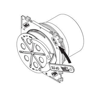
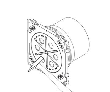
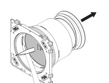
7 6 Montage (Gebäudeaußenseite) 1 Falls Schutzfolie vorhanden, bitte abziehen (vorher leicht erwärmen). D Verschlussdeckel nicht mit Hammer oder scharfem Gegenstand einschlagen! Geöffnete Kabeldurchführungen, welche als Reservedurchführungen genutzt werden sollen bzw. Verschlussdeckel, die versehentlich geöffnet wurden, sind grundsätzlich mit neuen Verschlussdeckeln HSI 150-D zu verschließen! Demontierte bzw. beschädigte Verschlussdeckel dürfen nicht wieder verwendet werden! Die Schlüsselaufnahmen im schwarzen Verschlussdeckel falls erforderlich von Betonresten säubern. Verschlussdeckel mit dem Gelenkstirnlochschlüssel SLS 6G (Zubehör) über die Schlüsselaufnahmen mit einer Drehbewegung nach links öffnen. Bei Einfachdichtpackungen mit Wandstärke 70 bis 150 mm wird der Blinddeckel (Zweitabdichtung) auf der Anschlussseite (Bajonettaufnahme) mit einem Hammer eingeschlagen und entfernt. Optional kann der Blinddeckel auch rückseitig eingeschlagen werden. Anschließend wird der PE-Deckel auf der Rohrseite entfernt (HSI 150-K70 und -K80 ohne PE-Deckel). Beim Einschlagen des Blinddeckels (Zweitabdichtung) darf die Bajonettaufnahme der Dichtpackung nicht beschädigt werden. 5 Nach der Kabelverlegung den Innenraum der Kabeldurchführung sowie die Kabel mit Kabelreiniger KR60 (Zubehör) von Verschmutzungen reinigen und Dichtfläche auf Beschädigungen prüfen. Kabel dürfen im Dichtbereich keine durchgängigen Längsriefen aufweisen (Kabel evtl. ein Stück vor- oder zurückschieben bis keine Längsriefen mehr sichtbar sind). 6 7 Geteilten Adapterring über die Kabel klappen und die Ringenden miteinander verbinden (Detail). Adapterring in die Kabeldurchführung einführen bis dieser bündig am Rahmen der Dichtpackung anliegt. Markierungsstriche des Adapteringes müssen mit den Markierungspfeilen der Dichtpackung übereinstimmen (siehe Pos. 7). Die Aussparungen vom Adapterring müssen über das Bajonett der Dichtpackung einrasten. Die Dichtfläche des Adapterringes muss eben sein und darf keine Erhebungen aufweisen. 8 9 Durchmesser der Kabel mit Messschieber ermitteln. Anschließend die Segmentringe eines Ringraumdichtungsabschnittes entsprechend dem ermittelten Durchmesser der Kabel auswählen (Durchmesserbereich ist auf den Segmenten im Detail sichtbar), an der Trennstelle mit mitgeliefertem Messer einschneiden und anschließend abreißen. Dieser Schritt muss nun an den verbleibenden Segmenten der Ringraumdichtungsabschnitte identisch wiederholt werden; die Anzahl der entfernten Segmente muss an allen Ringraumdichtungssegmenten übereinstimmen. 7
8 D 10 Danach nur die Schnittflächen und Kabelabdichtflächen der Ringraumdichtung mit Gleitmittel GM (Lieferumfang) schmieren. Nicht die Außendichtfläche der Ringraumdichtung schmieren (Detail 10a). 11 Die Ringraumdichtung über die Kabel klappen und bündig bis zur Außenkante des Adapterringes schieben. Die Außendichtfläche der Ringraumdichtung sowie die Innenfläche des Adapterringes müssen fettfrei und trocken sein (mit mitgeliefertem Reinigungstuch säubern). 12 Nicht belegte Öffnungen der Ringraumdichtungen HSI 150-DG-3/24-54 bzw. HSI 150-DG-6/10-36 müssen mit den mitgelieferten Blindstopfen verschlossen werden. Blindstopfenöffnung muss in Montagerichtung zeigen. 13 Zum Schluss alle Schrauben (Inbus-Schlüsselgröße SW5) der Ringraumdichtung mit Verlängerung kreuzweise anziehen bis das vorgegebene Drehmoment (Tabelle) erreicht ist. Bei der Ringraumdichtung HSI 150-DG-6/10-36 werden zuerst die Schrauben der mittleren Pressplatte leicht angezogen und danach die beiden äußeren Pressplatten. Dies geschieht im Wechsel bis das vorgegebene Drehmoment (Tabelle) erreicht ist. Tabelle Wenn alle Schrauben angezogen sind, muss das Drehmoment an der Ringraumdichtung überprüft und ggf. nachgezogen werden. Bezeichnung Anzahl der Bohrungen Durchmesserbereich (mm) Anzugsmoment HSI 150-DG-1/ Nm HSI 150-DG-1/ Nm HSI 150-DG-3/ Nm HSI 150-DG-6/ Nm Unsere Produkte sind entsprechend ihrer vorgesehenen Verwendungsweise ausschließlich für den Einbau in Bauwerke entwickelt, deren Baustoffe dem derzeitigen Stand der Technik entsprechen. Für eine andere oder darüber hinaus gehende Verwendung, sofern sie nach Rücksprache mit uns nicht ausdrücklich schriftlich bestätigt wurde, übernehmen wir keine Haftung. Service-Telefon Änderungen vorbehalten. 8
9 Contents 1 General information and intended use 2 Safety instructions 3 Description 4 Delivery package 5 Required tools and equipment 6 Installation (exterior side of the building) GB 1 General and intended use The HSI 150-DG system cover is suitable for retrofitting and inserting 1 cable with an outer diameter of between 36 and 70 mm, 1 cable with an outer diameter of between 70 and 112 mm, 3 cables with an outer diameter of between 24 and 54 mm or respectively 6 cables with an outer diameter of between 10 and 36 mm. 2 Safety instructions Protect the system cover from damage, moisture and contamination during installation. Check the delivery for completeness and all of the individual parts for any signs of damage. Only undamaged parts may be installed. When installing the system cover, the relevant regulations of employer's liability insurance associations, the VDE [Association for Electrical, Electronic & Information Technologies] requirements, the applicable national safety and accident prevention regulations and the directives (work instructions and documented procedures) of your company must be observed. No cleaning agents containing solvents must be used to clean the cable entries! We recommend Hauff-Technik M.T.X.60 cable cleaner. Press seals are not fixed points or bearings and, as such, cannot sustain mechanical forces. Any anticipated depressions must be compensated for by the installation of centring aids or spacers in the liners or core drillings (HSI 150-DF aluminium flange). For the connection of pipes or ducts (DN100/DN125) to the HSI 150 system, the upper application range is restricted as a result of the reduction of the clearance / clear width. 3 Description (e.g.: HSI 150-DG-6/10-36) Sealing plug Press seal HSI 150-DG-6/10-36 Middle press plate HSI 150-K wall insert Outer press plate Cable Adapter ring 9
10 4 Delivery package The delivery package of the HSI 150-DG system cover consists of: 1 HSI 150-DG press seal 1 HSI 150-AR-DG adapter ring 1 GM lubricant pen 1 knife 1 cleaning cloth Optional: 3 HSI 150-PA-3/24-54 press plate covers suitable for HSI 150-DG-3/24-54 or respectively 1 HSI 150-PA-6/10-36 press plate covers suitable for HSI 150-DG-6/ Required tools and equipment GB For the proper installation of the HRD150-DG press seal, you will require the following tools and equipment besides your standard tools: Tools: HSI 150-DG installation set consisting of: 1 torque spanner 4-20 Nm, 1/4 inch mm extension, 1/4 inch mm extensions, 1/4 inch 1 adapter for cordless screwdriver, square, 1/4 inch 1 M6 socket, wrench size 5, 1/4 inch 1 M6 socket, 100 mm long with spherical head, 1/4 inch 1 SLS 6G flexible head spanner (Hauff) Equipment: 1 KR 60 cable cleaner (Hauff) 1 sliding caliper 1 cleaning cloth 1 cordless screwdriver (3 sealing plugs suitable for HSI 150-DG-3/24-54 or respectively 6 sealing plugs suitable for HSI 150-DG-6/10-36) Key 1 Work steps Instructions 10
11 6 Installation (exterior side of building) 1 Remove protective film if present (heat slightly beforehand). GB Do not knock the lock cover in with a hammer or sharp object! Open cable entries that are to be used as reserve entries or lock covers that were opened by mistake must be fitted with new HSI 150-D lock covers. Dismantled or damaged lock covers must not be reused! If necessary, clean out concrete residue from the openings for the flexible head spanner on the black lock cover. Using the SLS 6G flexible head spanner (accessories), open the lock cover via the key receptacles by turning it to the left. In single wall inserts with a wall thickness of 70 to 150 mm the dummy cover (second seal) on the connection side (bayonet mounting) is hammered in with a hammer and removed (optionally the dummy cover can also be hammered in on the back). The PE cover is then removed on the pipe side (HSI 150-K70 and -K80 without PE cover). When hammering in the dummy cover (second seal), the bayonet of the wall insert must not be damaged. 5 Once the cables have been laid, clean any contamination from the inside of the cable entry as well as the cables using KR 60 cable cleaner (accessories) and check the sealing surface for any damage. Cables must not show any continuous longitudinal grooves in the sealing area (push the cables forwards or backwards if necessary until the grooves are no longer visible). 6 7 Fasten the split adapter ring over the cables and connect the ends of the ring together (detail). Insert the adapter ring into the cable entry until it lies flush with the edge of the wall insert. The marking lines on the adapter ring must match the arrows marked on the wall insert (see pos. 7). The recesses from the adapter ring must lock over the bayonet of the wall insert. The sealing surface of the adapter ring must be smooth and plain inside the wall insert. 8 9 Measure the diameter of the cables using a sliding caliper. Then select the segmented ring of a press seal section according to the measured diameter of the cables (diameter range is visible on the segments in the detail drawing), cut into the sectioning point using the knife provided and pull section away. You must then repeat this step in exactly the same way at the remaining segments of the press seal sections; the number of segments removed must be identical at all press seal sections. 11
12 GB 10 Then, only lubricate the cutting surfaces and cable sealing surfaces of the press seal using GM lubricant (delivery package). Do not lubricate the outer sealing surface of the press seal (detail 10a). 11 Fasten the press seal over the cables and push it flush against the outside edge of the adapter ring. The outer sealing surface of the press seal and the inner surface of the adapter ring must be free of lubricant and dry (clean with cleaning cloth provided). 12 Unassigned openings of the press seal HSI 150-DG-3/24-54 or respectively HSI 150-DG-6/10-36 must be sealed with the supplied sealing plugs. Blind sealing plug opening must point in direction of installation. 13 Finally, tighten all of the screws (Allen key size SW 5) of the press seal with the extension in a crossover pattern until the specified torque is reached (table). For the HSI 150-DG-6/10-36 press seal, first slightly tighten the screws of the middle press plate, then slightly tighten both of the outer press plates. Continue to do this alternately until the specified torque (table) is reached. Table Once all of the cables have been laid, check the torque at the press seal and tighten if necessary. Designation Number of bores Diameter range (mm) Tightening torque HSI 150-DG-1/ Nm HSI 150-DG-1/ Nm HSI 150-DG-3/ Nm HSI 150-DG-6/ Nm As indicated in the instructions for use, our products have been designed exclusively for installation in buildings made from state-of-the-art construction materials. We do not accept liability for use deviating from or beyond this unless our express written confirmation has been obtained in advance. Service-phone Subject to change. 12
13 Sommaire 1 Généralités et usage 2 Consignes de sécurité 3 Description 4 Contenu de la livraison 5 Outils et dispositifs d'aide requis 6 Montage (extérieur du bâtiment) F 1 Généralités et usage L anneau d étanchéité HSI 150-DG est idéal pour des câbles déj placés et le transit de 1 câble avec un diam tre extérieur de mm resp. 1 câble d un diam tre extérieur de mm resp. 3 câbles avec un diam tre extérieur de mm resp. 6 câbles d un diam tre extérieur de mm 2 Consignes de sécurité Lors des travaux de montage, protéger le couvercle contre tout endommagement, l'humidité et les saletés. Vérifier contenu de la livraison et que les pi ces détachées ne soient pas endommagées. Seules des pi ces en bon état doivent tre montées. Lors de l'installation du couvercle, il convient de respecter les dispositions régies par les organismes professionnels, les dispositions de la VDE, les prescriptions nationales pour les mati res de sécurité et de prévention des accidents ainsi que les directives (instructions de travail et de procédure) de votre société. Pour nettoyer les passe-câbles, ne pas utiliser de produits nettoyants base de solvants!nous recommandons le produit nettoyant pour câble Hauff-Technik M.T.X.60. Les joints annulaires ne sont pas des points fixes ou des supports et, par conséquent, ne peuvent pas absorber les efforts mécaniques. Les affaissements prévisibles doivent tre compensés par le montage d'aides au centrage et d'entretoises dans les gaines et les carottages (brides aluminium HSI 150-DF). Lors du raccordement gaines de tirage (DN100/DN125) au syst me HSI 150, la plage d utilisation supérieure est restreinte en raison du faible diam tre ou de la faible largeur de ces gaines. 3 Description (ex. : HSI 150-DG-6/10-36) Bouchons Joint annulaire en caoutchouc HSI 150-DG-6/10-36 Plaque d'appui centrale Passage simple face HSI 150-K Plaque d'appui extérieure Anneau adaptateur Câble 13
14 4 Contenu de la livraison Sont fournis dans le contenu de livraison du couvercle HSI 150-DG : 1 joint annulaire en caoutchouc HSI 150-DG 1 anneau adaptateur HSI 150-AR-DG 1 tube de lubrifiant GM 1 couteau 1 chiffon En option : 3 pi ces d étanchéité pour des plaques de presse en acier HSI 150-PA-3/24-54 calibré pour HSI 150-DG-3/ pi ce d étanchéité pour des plaques de presse en acier HSI 150-PA-6/10-36 calibré pour HSI 150-DG-6/ Outils et dispositifs d'aide requis Pour installer correctement le joint annulaire en caoutchouc HRD150-DG, les outils et dispositifs d'aide suivants sont nécessaires en plus des outils standard : Outils : kit d'assemblage HSI 150-DG se composant de : 1 clé dynamométrique 4-20 Nm, pouce 1 extension de 100 mm, de pouce 2 extensions de 150 mm, de pouce 1 adaptateur pour visseuse accu 100 mm, pouce 1 embout de tournevis M6 T 5, pouce 1 embout 100 mm M6 avec t te arrondie hexagonale pouce 1 clé ergots articulée SLS 6G (Hauff) Dispositifs d'aide : 1 produit nettoyant pour câble KR60 (Hauff) 1 pied coulisse 1 chiffon 1 visseuse sans fil F (3 Bouchon pour HSI 150-DG-3/ Bouchon pour HSI 150-DG-6/10-36) Légende 1 Étapes de travail Remarques respecter 14
15 6 Montage (extérieur du bâtiment) 1 Si il y a un film de protection, le retirer (le préchauffer légèrement, détail 1). F Ne pas utiliser de marteau ou d objet tranchant pour démonter le couvercle (détail 3 et précédent)! Poser des nouveaux couvercles HSI 150-D sur les passe-câbles ouverts utilisés comme passages de réserve ou remplacer les couvercles qui ont été ouverts accidentellement. Ne pas réutiliser les couvercles démontés ou endommagés! Nettoyer les résidus de béton dans les encoches prévues pour le placement de la clé dans le couvercle noir, si nécessaire (détail 2). Ouvrir le couvercle avec une clé ergots articulée SLS 6G (accessoires) placée dans les encoches prévues en exerçant un mouvement anti horlogique (détail 3). Pour des passe-câbles simples d une épaisseur de 70 à 150 mm, le couvercle de fermeture ( deux joints) est frappé dans le côté de raccordement (emmanchement à baïonnette) et retiré (le couvercle de fermeture peut également être frappé sur la face arrière). Retirer ensuite le couvercle en PE du côté tuyau (HSI 150-K70 et K80 sans couvercle en PE). Lors de la mise en place du couvercle de fermeture ( deux joints), la ba onnette du passecâble ne doit pas tre endommagée. 5 Apr s avoir placé les câbles, nettoyer les saletés l'intérieur du passe-câbles et sur les câbles avec du produit nettoyant pour câbles KR60 (accessoires) et vérifier si la surface d'étanchéité est en bon état (détail 5). Dans la zone d'étanchéité, les câbles ne doivent pas présenter de stries longitudinales continues (le cas échéant, pousser le câble vers l'avant ou l'arrière jusqu'à ce que les stries longitudinales ne soient plus présentes à cet endroit). 6 7 Placer l'anneau adaptateur autour des câbles et relier les extrémités de l'anneau entre elles (détail 6). Introduire l'anneau adaptateur dans le passe-câbles jusqu' ce qu'il affleure avec le cadre du passage simple face. Les rep res de marquage de l anneau adaptateur doivent concorder avec les fl ches de marquage sur la face carrée du passage (détail 7). Les évidements de l'anneau adaptateur doivent s'enclencher dans le raccord ba onnette du passage simple face. La surface d'étanchéité de l'anneau adaptateur doit tre plane et ne présenter aucune bourrelet. 8 9 Déterminer le diam tre des câbles avec le pied coulisse (détail 8). Déterminer pour chaque ouverture le câble correspondant. Enlever subséquemment les segments jusqu ce que la plage de diam tre indiqué sur les segments corresponde au diam tre de câble. Procéder comme suit: entailler, avec le cutter livré, le point d attache des segments et ensuite arracher ceux-ci la main (detail 9). Faire cette opération pour chaque partie de l ouverture. En final tous les segments d une m me ouverture doivent avoir la m me plage de diam tres. Faire cela pour chaque ouverture. 15
16 F 10 Ensuite, graisser uniquement les surfaces intérieures du joint annulaire en caoutchouc avec le lubrifiant GM (contenu dans la livraison, détail 10). Ne pas graisser la surface d'étanchéité extérieure des sections du joint annulaire en caoutchouc (vue détaillée 10a). 11 Passer le joint annulaire en caoutchouc autour des câbles et l avancer pour qu il affleure avec l anneau adaptateur. La surface d'étanchéité extérieure du joint annulaire en caoutchouc ainsi que la surface intérieure de l'anneau adaptateur doivent tre exemptes de graisser et s ches (nettoyer avec le chiffon contenu de la livraison, détail 11). 12 Les ouvertures non utilisées du joint annulaire en caoutchouc HSI 150-DG-3/24-54 resp. HSI 150-DG-6/10-36 devrait tre fermer par des bouchon celui fourni. L'ouverture du bouchon doit indiquer le sens de montage (détail 12). 13 Pour terminer, serrer toutes les vis (clé pour vis à six pans creux nr 6) du joint annulaire en caoutchouc avec extension jusqu l atteinte du couple prescrit (tableau). Faire cela progressivement et ne pas exercer directement le couple indiqué sur une seule vis ou une seule partie du joint annulaire. Travailler en étoile (détail 13). Sur le joint annulaire HSI 150-DG-6/10-36, commencer par serrer les vis de la plaque de serrage centrale puis celles des deux plaques de serrage extérieures. Procéder par alternance jusqu l atteinte du couple de serrage (tableau) prescrit (détail 13a). Si toutes les vis sont bien serrées, vérifier le couple de serrage au niveau du joint annulaire en caoutchouc et resserres, le cas échéants. Tableau Désignation Nombre d ouvertures Plage de diamètre (mm) Couple de serrage HSI 150-DG-1/ Nm HSI 150-DG-1/ Nm HSI 150-DG-3/ Nm HSI 150-DG-6/ Nm Conformément l usage prévu, nos produits sont conçus exclusivement pour tre intégrés dans des constructions dont les matériaux sont conformes la réglementation technique en vigueur. Nous déclinons toutes responsabilités dans le cas d une utilisation non-conforme pour l usage indiqué si nous n avons pas donné notre accord par écrit apr s consultation. Téléphone SAV Sous réserve de modifications. 16
17 Inhoud 1 Algemeen en toepassing 2 Veiligheidsinstructies 3 Beschrijving 4 Leverings Inhoud 5 Benodigd gereedschap en hulpmiddelen 6 Montage (buitenzijde gebouw) NL 1 Algemeen en toepassing Het systeemdeksel HSI 150-DG is voor montage naderhand en voor doorvoer van 1 Kabel met buitendiameter mm resp. 1 kabel met buitendiameter mm. 3 kabels met buitendiameter mm resp. 6 kabels met buitendiameter mm geijkt. 2 Veiligheidsinstructies Bescherm het systeemdeksel bij de montage-installatie tegen beschadiging, vocht en verontreiniging. Controleer de levering op volledigheid, en alle losse onderdelen op eventuele schade. Er mogen alleen onbeschadigde delen worden gemonteerd. Bij de installatie van het systeemdeksel moeten de geldende voorschriften van de beroeps, de VDEbepalingen, de geldende nationale veiligheids- en ongevallenpreventievoorschriften en de richtlijnen (werk- en procedure-instructies) van uw onderneming worden aangehouden. Voor de reiniging van de kabeldoorvoeren mogen geen reinigingsmiddelen met oplosmiddelen worden gebruik! Wij adviseren Hauff-Technik kabelreiniger M.T.X.60. Ronde doorvoerdichtingen zijn geen vaste punten of lagers en kunnen dus geen mechanische krachten opnemen. Te verwachten verzakkingen moeten door inbouw van centreerhulpmiddelen resp. afstandshouders in de doorvoerbuizen of kernboringen (aluminium flens HSI 150-DF) worden opgevangen. Voor deconnectic van kabels en buizen (DN100/DN125) op het systeem HSI 150, wordt als gevolg van de reducering van de inwendige diameter resp. de inwendige breedte, het maximum toepassingsgebied beperkt. 3 Beschrijving (voorbeeld: HSI 150-DG-6/10-36) Blindpluggen Ronde doorvoerdichting HSI 150-DG-6/10-36 Middelste persplaat Afdichtpakking HSI 150-K Buitenste persplaat Adapterring Kabel 17
18 4 Leveringsomvang Tot de leverings inhoud van het systeemdeksel HSI 150-DG behoren: 1 ronde doorvoerdichting HSI 150-DG 1 adapterring HSI 150-AR-DG 1 glijmiddelstift GM 1 mes 1 schoonmaakdoek Optie: 3 drukplaat afdichtingen HSI 150-PA-3/24-54 geijkt voor HSI 150-DG-3/ drukplaat afdichting HSI 150-PA-6/10-36 geijkt voor HSI 150-DG-6/ Benodigd gereedschap en hulpmiddelen Voor de correcte installatie van de ringkamerafdichting HRD 150-DG heeft u naast het standaard gereedschap ook de volgende gereedschappen en hulpmiddelen nodig: Gereedschappen: montageset HSI 150-DG bestaande uit: 1 draaimomentsleutel 4-20 Nm, 1/4 1 verlenging 100 mm, 1/4 2 verlengingen 150 mm, 1/4 1 houder voor akku schroefmachine, vierkant, 1/4 1 steeksleutelbit M6, SW 5, 1/4 1 steeksleutelbit M6, 100 mm lang met kogelkop, 1/4 1 stuk scharnierhaaksleutel SLS 6G (Hauff) Hulpmiddelen: 1 kabelreiniger KR60 (Hauff) 1 schuifmaat 1 schoonmaakdoek 1 accuschroefmachine NL (3 blindstoppen geijkt voor HSI 150-DG-3/ blindstoppen geijkt voor HSI 150-DG-6/10-36) Legenda 1 Arbeidsstappen aan te houden instructies 18
19 6 Montage (buitenzijde gebouw) 1 Indien aanwezig beschermfolie, a.u.b. aftrekken (eerst iets voorverwarmen). NL Afsluitdeksel niet met hamer of scherp object inslaan! Geopende kabeldoorvoeren welke als reservedoorvoeren moeten worden gebruikt resp. afsluitdeksels die per ongeluk worden geopend, moeten van nieuwe afsluitdeksels HSI 150-D worden voorzien. Gedemonteerde resp. beschadigde deksels mogen niet worden hergebruikt! Indien nodig betonresten uit de sleutelgaten in het zwarte deksel verwijderen. Deksel met de sleutel SLS 6G (toebehoren) via de sleutelgaten met een draaibeweging naar links openen. Bij enkelzijdige dichtpakkingen met wanddiktes van 70 tot 150 mm wordt het blinddeksel (Tweede afdichting) op de aansluitzijde (bajonet uiteinde) met een hamer ingeslagen en verwijderd (optioneel kan het afsluitdeksel op de rugzijde ook met een hamer ingeslagen worden). Aansluitend wordt het PE-deksel op de buis zijde verwijderd (HSI 150-K70 en -K80 zonder PE-deksel). Bij het inslagen van het blinddeksel (tweede afdichting) de bajonetsluiting van de dichtpakking NIET beschadigen. 5 Na het installeren van de kabel de binnenruimte van de kabeldoorvoer en de kabel met kabelreiniger KR 60 (toebehoren) reinigen en de afdichtingsoppervlakken controleren op beschadigingen. Kabels mogen in het afdichtingsgebied geen doorlopende langsgroeven hebben (kabel eventueel een stuk vooruit of achteruit schuiven tot geen langsgroeven meer zichtbaar zijn). 6 7 Gedeelde adapterring over de kabel klappen en de ringeinden onderling verbinden (detail). Plaats de adapterring in de kabeldoorvoer tot deze vlak tegen het kader van de afdichtpakking aanligt. De markeringsstrepen van de adapterring moeten samenvallen met de markeringspijlen op de afdichtpakking (zie pos. 7). De uitsparingen van de adapterring moeten over de bajonet van de afdichtpakking geklemd worden. Het afdichtvlak van de adapterring moet vlak zijn en mag geen oneffenheden vertonen. 8 9 Meet de diameter van de kabel met de schuifmaat. Aansluitend de segmentring van een ronde doorvoerdichtingsdeel, overeenkomstig de diameter van de kabel kiezen (diameterbereik is vermeld op de segmenten), op de scheidingsplaats met het meegeleverde mes insnijden en daarna afscheuren. Deze stap moet nu voor de overige segmenten van de ronde doorvoerdichting worden herhaald; het aantal van de verwijderde segmenten moet op alle segmenten van de ringkamerafdichting overeenkomen. 19
20 NL 10 Daarna alleen de snijvlakken en kabelbinnenvlakken van de ronde doorvoerdichting met glijmiddel GM (meegeleverd) insmeren. Niet de buitenafdichtoppervlakken van de rone doorvoerdelen insmeren (detail 10a). 11 De ronde doorvoerdichting over de kabel klappen en vlak tot aan de buitenkant van de adapterring schuiven. De buitenafdichtoppervlakken van de ronde doorvoerdichting en de binnenvlakken van de adapterring moeten vetvrij en droog zijn (met meegeleverde doek schoonmaken). 12 Niet gebruikte openingen van de drukring dichting HSI 150-DG-3/24-54 resp. HSI 150-DG-6/10-36 dienen met de meegeleverde blindstoppen afgedicht te worden. Blindstopopening moet in de montagerichting wijzen. 13 Tot slot alle schroeven (inbussleutel SW5) van de ronde doorvoerdichting met verlenging, kruisgewijs aantrekken tot het gegeven draaimoment (tabel) is bereikt. Bij de ronde doorvoerdichting HSI 150-DG-6/10-36 worden eerst de schroeven van de middelste persplaat licht aangetrokken en daarna de beide buitenste persplaten. Dit gebeurt afwisselend, tot het gegeven draaimoment (tabel) is bereikt. Tabel Wanneer alle schroeven aangedraaid zijn, moet het koppel aan de ronde doorvoer gecontroleerd en eventueel nagetrokken worden Benaming Aantal van de boringen Diameterbereik (mm) Aandraaimoment HSI 150-DG-1/ Nm HSI 150-DG-1/ Nm HSI 150-DG-3/ Nm HSI 150-DG-6/ Nm Onze producten zijn uitsluitend bedoeld voor gebruik conform inbouw in bouwwerken ontwikkeld, waarvan de materialen aan de huidige stand van de techniek voldoen.voor een andere toepassing dan wel ander gebruik, voor zover dit na overleg met ons niet uitdrukkelijk schriftelijk is bevestigd, aanvaarden wij geen aansprakelijkheid. Servicetelefoon Wijzigingen voorbehouden! 20
21 Spis treści 1 Informacje ogólne i przeznaczenie 2 Wskazówki dotyczące bezpieczeństwa 3 Opis 4 Zakres dostawy 5 Niezbędne narzędzia i środki pomocnicze 6 Montaż (na zewnątrz budynku od strony wykopu) PL 1 Informacje ogólne i przeznaczenie produktu Pokrywa systemowa HSI 150-DG jest przeznaczona do wprowadzenia i uszczelnienia (także pomontażowego): 1 kabla o średnicy od 36 do 70 mm lub 1 kabla o średnicy od 70 do 112 mm, lub 3 kabli o średnicy od 24 do 54 mm, lub 6 kabli o średnicy od 10 do 36 mm. 2 Wskazówki dotyczące bezpieczeństwa Podczas montażu pokrywę systemową należy chronić przed uszkodzeniami, wilgocią i zanieczyszczeniami. Sprawdzić, czy dostawa jest kompletna oraz czy poszczególne części nie są uszkodzone. Dozwolony jest montaż wyłącznie nieuszkodzonych części. Podczas montażu pokrywy systemowej należy przestrzegać obowiązujących norm i przepisów. Do czyszczenia przepustów kablowych nie wolno używać środków czyszczących zawierających rozpuszczalniki! Zalecamy używanie preparatu do czyszczenia kabli Hauff-Technik M.T.X.60. Gumowe wkłady uszczelniające nie są punktami stałymi ani łożyskami, dlatego też nie są odporne na działanie sił mechanicznych. Należy zapewnić niwelację ewentualnych obniżeń poprzez montaż elementów centrujących lub wsporników w rurach przepustowych lub przewiertach (kołnierz aluminiowy HSI 150-DF). W przypadku podłączeń rur ochronnych (DN100/DN125) do systemu HSI 150, wskutek redukcji otworu przelotowego względem przepustu obszar zastosowania zostaje ograniczony. 3 Opis (przykład: HSI 150-DG-6/10-36) Zaślepki Pokrywa HSI 150-DG-6/10-36 środkowa płytka dociskowa Przepust HSI 150 do zabetonowania zewnętrzna płytka dociskowa Adapter Kabel 21
22 4 Zakres dostawy Zakres dostawy pokrywy systemowej HSI 150-DG obejmuje: 1 pokrywa HSI 150-DG 1 Adapter HSI 150-AR-DG 1 środek poślizgowy w sztyfcie GM 1 nóż 1 ściereczka Opcja: 3 sztuki osłony płytek dociskowych HSI 150-PA-3/24-54 do HSI150-DG-3/24-54 lub 1 sztuka osłony płytek dociskowych HSI 150-PA-6/10-36 do HSI150-DG-6/ Niezbędne narzędzia i środki pomocnicze Do prawidłowego montażu gumowego wkładu uszczelniającego HRD150-DG potrzebne są, oprócz standardowych narzędzi, następujące narzędzia i środki pomocnicze: Narzędzia: zestaw montażowy HSI 150-DG, składający się z: 1 Zestaw montażowy HSI 150-DG, w którego skład wchodzą: 1 klucz dynamometryczny 4-20 Nm, 1/4 cala 1 przedłużka 100 mm, 1/4 cala 2 przedłużki po 150 mm, 1/4 cala 1 uchwyt czworokątny do wkrętarki akumulatorowej, 1/4 cala 1 nasadka do klucza nasadowego M6, rozm. 5, 1/4 cala 1 nasadka do klucza nasadowego M6, długość 100 mm, z końcówką kulową, 1/4 cala 1 klucza SLS 6G (Hauff) Środki pomocnicze 1 preparat do czyszczenia kabli KR60 (Hauff) 1 suwmiarka 1 ściereczka 1 wkrętak akumulatorowy (3 zaślepek do otworów w HSI 150-DG-3/24-54 lub 6 zaślepek do otworów w HSI 150-DG-6/10-36) PL Legenda 1 Czynności Ważne wskazówki 22
23 6 Montaż (na zewnątrz budynku od strony wykopu) 1 PL Jeżeli na przepuście kablowym HSI 150 jest założona folia ochronna, należy ją lekko ogrzać i ściągnąć. Nie rozbijać pokrywy zamykającej młotkiem ani innym przedmiotem o ostrych krawędziach! Otwarte przepusty kablowe przeznaczone do wykorzystania jako przepusty zapasowe lub przepusty, z których przypadkowo zdjęto pokrywę zamykającą, należy wyposażyć w nowe pokrywy zamykające HSI 150-D! Zdemontowanych lub uszkodzonych pokryw zamykających nie należy ponownie wykorzystywać! W razie potrzeby oczyścić otwór pod klucz w czarnej pokrywie zamykającej z resztek betonu. Chwytając kluczem SLS 6G (akcesoria) za otwór pod klucz, otworzyć pokrywę zamykającą ruchem obrotowym w lewo. W przypadku jednostronnych przepustów kablowych w ścianach o grubości od 70 do 150 mm pokrywa zamykająca (dodatkowe uszczelnienie) po stronie przyłącza (mocowanie bagnetowe) jest wbijana i usuwana za pomocą młotka (ew. pokrywę zamykającą można wbić od strony tylnej). Następnie należy usunąć pokrywę PE po stronie rury (HSI 150-K70 i -K80 bez pokrywy PE). Podczas wbijania pokrywy zamykającej (dodatkowe uszczelnienie) nie można dopuścić do uszkodzenia przepustu kablowego. 5 Po wciągnięciu kabli oczyścić wewnętrzną część przepustu kablowego oraz kable preparatem do czyszczenia kabli KR60 (akcesoria) i skontrolować powierzchnię uszczelniającą pod kątem uszkodzeń. W obszarze uszczelnienia kable nie mogą posiadać ciągłych rowków wzdłużnych (ewentualnie nieco przesunąć kable do przodu lub do tyłu, aż rowki wzdłużne nie będą widoczne). 6 7 Założyć adapter z rozłączonymi końcami na kable i połączyć końce pierścienia (rysunek szczegółowy). Wprowadzić adapter do przepustu kablowego, aż znajdzie się w jednej linii z znacznikami na froncie przepustu kablowego HSI 150. Kreski na adapterze muszą zbiegać się ze strzałkami na przepuście kablowym HSI 150 (zobacz poz. 6). Wycięcia w adapterze muszą zaskoczyć na złącza mocujące wewnątrz przepustu kablowego HSI 150. Powierzchnia uszczelniająca adaptera musi być równa i nie może posiadać żadnych pofałdowań. 8 9 Zmierzyć średnice kabli za pomocą suwmiarki. Następnie wybrać pierścienie segmentowe pokrywy stosownie do ustalonej średnicy kabli (zakres średnic jest widoczny na segmentach na rysunku szczegółowym), naciąć dołączonym nożem w miejscu przedzielenia i oderwać. Krok ten należy powtórzyć w ten sam sposób na pozostałych segmentach pokrywy; liczba usuniętych segmentów musi być identyczna we wszystkich częściach pokrywy. 23
24 PL 10 Następnie nasmarować tylko powierzchnie przekroju i stykające się z kablem powierzchnie wewnętrzne pokrywy środkiem poślizgowym GM (dostarczany wraz z pokrywą). Nie smarować zewnętrznej powierzchni pokrywy (rysunek szczegółowy 9a). 11 Założyć gumowy wkład uszczelniający na kable i dokładnie dosunąć aż do krawędzi zewnętrznej adaptera. Zewnętrzna powierzchnia uszczelniająca pokrywy oraz powierzchnia wewnętrzna adaptera muszą być odtłuszczone i suche (oczyścić dołączoną ściereczką). 12 Niewykorzystane otwory HSI 150-DG-3/24-54 lub HSI 150-DG-6/10-36 należy zabezpieczyć dostarczonymi korkami. Otwór w zaślepce musi być zwrócony w kierunku wnętrza budynku. 13 Na koniec dokręcić na krzyż wszystkie śruby (kluczem imbusowym o rozmiarze 5 z przedłużką) pokrywy, aż do osiągnięcia podanego momentu obrotowego (tabela). W przypadku pokrywy HSI 150-DG-6/10-36 należy najpierw lekko dokręcić śruby środkowej płytki dociskowej, a następnie obu zewnętrznych płytek dociskowych. Należy je dokręcać naprzemiennie, aż do osiągnięcia podanego momentu obrotowego (tabela). Tabela Po dokręceniu wszystkich śrub, należy skontrolować osiagnięty moment obrotowy, ewentualnie dociagnać do otrzymania właściwych parametrów. Oznaczenie Liczba otworów Zakres średnic (mm) Moment pokrywie HSI 150-DG-1/ Nm HSI 150-DG-1/ Nm HSI 150-DG-3/ Nm HSI 150-DG-6/ Nm Nasze produkty, zgodnie z ich przeznaczeniem, zostały opracowane wyłącznie do montażu w budynkach wykonanych z materiałów budowlanych zgodnych z aktualnym stanem wiedzy technicznej. Nie ponosimy odpowiedzialności za wszelkie inne lub wykraczające poza wyżej opisane zastosowania, o ile nie zostały one przez nas w sposób wyraźny potwierdzone na piśmie. Serwis-telefon: Producent zastrzega sobie prawo do wprowadzania zmian! 24
25 Notizen / Notes / Remarques / Opmerkingen / Notatki 25
26 Wir weisen ausdrücklich darauf hin, dass bei Abweichung von den Angaben in der Montageanleitung und bei unsachgemäßer Verwendung unserer Produkte sowie deren Kombination mit Fremdprodukten für eventuell auftretende Folgeschäden keinerlei Gewährleistung übernommen wird. Hauff-Technik GmbH & Co. KG Robert-Bosch-Straße Hermaringen, GERMANY Tel Fax office@hauff-technik.de ma_hsi150_dg_
Montageanweisung HSI150-DG zur nachträglichen Montage. Installation Instruction HSI150-DG for retrofitting
 Montageanweisung HSI150-DG zur nachträglichen Montage Installation Instruction HSI150-DG for retrofitting Instructions de montage HSI150-DG pour un montage ultérieur Montage-instructie HSI150-DG voor montage
Immer. Sicher. Dicht.
 Immer. Sicher. Dicht. Montageanweisung HRK100-SSG-1/18-65 und HRK100-SSG-4/8-30 Installation Instruction HRK100-SSG-1/18-65 and HRK100-SSG-4/8-30 Instructions de montage HRK100-SSG-1/18-65 et HRK100-SSG-4/8-30
Immer. Sicher. Dicht.
 Immer. Sicher. Dicht. Montageanweisung HRK150-SSG-1/36-70, -1/70-112, -3/24-54 und -6/10-36 Installation Instruction HRK150-SSG-1/36-70, -1/70-112, -3/24-54 and -6/10-36 Instructions de montage HRK150-SSG-1/36-70,
Immer. Sicher. Dicht.
 Immer. Sicher. Dicht. Montageanweisung HRK200-SSG-1/110-162, -3/40-72 Installation Instruction HRK200-SSG-1/110-162, and -3/40-72 Instructions de montage HRK200-SSG-1/110-162, et -3/40-72 Montage-instructie
Immer. Sicher. Dicht.
 Immer. Sicher. Dicht. Montageanweisung - Ringraumdichtung HRD 150/160-2SGi zur nachträglichen Montage in HSI 150. Press seal installation instructions HRD 150/160-2SGi for retrofit installation in HSI
/2004 RENAULT MEGAN SCENIC I R/011. Cat. No. e20. e20*94/20*0680*00 D = 7,72kN. 1400Kg 75Kg. D (kn) = x 0, MAX kg.
 = x 0, MAX kg.") RENAULT MEGAN SCENIC I 1998-09/2004 Cat. No. R/011 e20 e20*94/20*0680*00 1400Kg 75Kg D = 7,72kN D (kn) = MAX kg x MAX kg x 0,00981 MAX kg + MAX kg PRZEKRÓJ A-A 75 min. 75 min. 30 o max. A R 14,5 max. R40
RENAULT MEGAN SCENIC I 1998-09/2004 Cat. No. R/011 e20 e20*94/20*0680*00 1400Kg 75Kg D = 7,72kN D (kn) = MAX kg x MAX kg x 0,00981 MAX kg + MAX kg PRZEKRÓJ A-A 75 min. 75 min. 30 o max. A R 14,5 max. R40
11/ RENAULT MEGANE II 3/5 d. R/030. Cat. No. e20. e20*94/20*0375*00 D = 7,56kN. 1350Kg 75Kg. D (kn) = x 0, MAX kg.
 = x 0, MAX kg.") RENULT MEGNE II 3/5 d. 11/2002 - Cat. No. R/030 e20 e20*94/20*0375*00 1350Kg 75Kg D = 7,56kN D (kn) = MX kg x MX kg x 0,00981 MX kg + MX kg PRZEKRÓJ - 75 min. 75 min. 30 o max. R 14,5 max. R40 max. 140
RENULT MEGNE II 3/5 d. 11/2002 - Cat. No. R/030 e20 e20*94/20*0375*00 1350Kg 75Kg D = 7,56kN D (kn) = MX kg x MX kg x 0,00981 MX kg + MX kg PRZEKRÓJ - 75 min. 75 min. 30 o max. R 14,5 max. R40 max. 140
Immer. Sicher. Dicht.
 Immer. Sicher. Dicht. Montageanweisung HSD-SSG für neu zu verlegende bzw. bereits verlegte Rohre Installation Instruction HSD-SSG for pipes to be newly laid or that have been already laid Instructions
RENAULT GRAND SCENIC II
 RENAULT GRAND SCENIC II 04.2004 - Cat. No. R/029 e20*94/20*0372*00 1350Kg 75Kg 8,02kN PRZEKRÓJ A-A 75 min. 75 min. 30 o max. A R 14,5 max. R40 max. A 140 min. 55 min. 100 max. 32 min. 30 o max. 350-420
Immer. Sicher. Dicht.
 Immer. Sicher. Dicht. Montageanweisung Kabel- und Rohrabdichtung HRD. Installation instructions HRD cable and pipe seal. Instructions d installation joint pour câbles et tubes HRD. Montage-instructies
02/02-05/ VOLKSWAGEN POLO htb. (9N) SEAT IBIZA W/022. Cat. No. E20 55R e20. 6,90 kn Kg 50 Kg
 SEAT IBIZA W/022. Cat. No. E20 55R e20. 6,90 kn Kg 50 Kg") VOLKSWAGEN POLO htb. (9N) SEAT IBIZA 02/02-05/09 05-08 at. No. W/022 e20 E20 55R-01-1045 1200 Kg 50 Kg 6,90 kn Moment skręcający dla śrub i nakrętek (8.8) Torgue settings for nuts and bolts (8.8) M8 25Nm
VOLKSWAGEN POLO htb. (9N) SEAT IBIZA 02/02-05/09 05-08 at. No. W/022 e20 E20 55R-01-1045 1200 Kg 50 Kg 6,90 kn Moment skręcający dla śrub i nakrętek (8.8) Torgue settings for nuts and bolts (8.8) M8 25Nm
06/ / MERCEDES C-KLASA (W-203) sed. MERCEDES C-KLASA (W-203) com. M/032. Cat. No. e20*94/20*0513*00. 10,00kN.
 sed. MERCEDES C-KLASA (W-203) com. M/032. Cat. No. e20*94/20*0513*00. 10,00kN.") MERCEDES C-KLASA (W-203) sed. MERCEDES C-KLASA (W-203) com. 06/2000-2007 04/2001-2007 Cat. No. M/032 e20*94/20*0513*00 1500Kg 75Kg 10,00kN Moment skręcający dla śrub i nakrętek (8.8) Torgue settings for
MERCEDES C-KLASA (W-203) sed. MERCEDES C-KLASA (W-203) com. 06/2000-2007 04/2001-2007 Cat. No. M/032 e20*94/20*0513*00 1500Kg 75Kg 10,00kN Moment skręcający dla śrub i nakrętek (8.8) Torgue settings for
Immer. Sicher. Dicht.
 Immer. Sicher. Dicht. Montageanweisung - Hauff-Mauerkragen HMK. DN110 DN200. Installation Instruction - Hauff wall collar HMK. DN110 DN200. Instructions de montage - Collerette d étanchéité Hauff HMK.
Immer. Sicher. Dicht.
 Immer. Sicher. Dicht. Montageanweisung für Systemdeckel HSI 150-D... in Schrumpftechnik und Rohranschlüsse Installation instructions for system cover HSI 150-D... using shrink-fit method and pipe connections
RENAULT LAGUNA com. R/018. Cat. No. e20. e20*94/20*0132*00 D = 8,50kN. 1500Kg 75Kg. D (kn) = x 0, MAX kg. MAX kg
 = x 0, MAX kg. MAX kg") RENAULT LAGUNA com. 2001 - Cat. No. R/018 e20 e20*94/20*0132*00 1500Kg 75Kg D = 8,50kN D (kn) = x x 0,00981 + PRZEKRÓJ A-A 75 min. 75 min. 30 o max. A R 14,5 max. R40 max. A 140 min. 55 min. 100 max. 32
RENAULT LAGUNA com. 2001 - Cat. No. R/018 e20 e20*94/20*0132*00 1500Kg 75Kg D = 8,50kN D (kn) = x x 0,00981 + PRZEKRÓJ A-A 75 min. 75 min. 30 o max. A R 14,5 max. R40 max. A 140 min. 55 min. 100 max. 32
PRZEKRÓJ A-A. The clearance specified in appendix VII, diagram 25a/b of Regulation No UN EU must be guaranteed at laden weight of the vehicle.
 PRZEKRÓJ - 75 min. 75 min. 30 o max. R 14,5 max. R40 max. 140 min. 55 min. 100 max. 32 min. 30 o max. 350-420 PL Należy zagwarantować przestrzeń swobodną według załącznika VII, rysunek 25a/b Regulaminu
01/ KIA SPORTAGE HYUNDAY TUCSON K/020. Cat. No. e20. e20*94/20*0371*00 D = 10,30kN. 2000Kg 80Kg. D (kn) = x 0, MAX kg.
 = x 0, MAX kg.") KIA SPORTAGE HYUNDAY TUCSON 01/2005-2004 - Cat. No. K/020 e20 e20*94/20*0371*00 2000Kg 80Kg D = 10,30kN D (kn) = MAX kg x MAX kg x 0,00981 MAX kg + MAX kg PRZEKRÓJ A-A 75 min. 75 min. 30 o max. A R 14,5
KIA SPORTAGE HYUNDAY TUCSON 01/2005-2004 - Cat. No. K/020 e20 e20*94/20*0371*00 2000Kg 80Kg D = 10,30kN D (kn) = MAX kg x MAX kg x 0,00981 MAX kg + MAX kg PRZEKRÓJ A-A 75 min. 75 min. 30 o max. A R 14,5
TOYOTA LAND CRUISER V8 T/039. Cat. No. E20-55R-01 D = 17,4kN. 140Kg. 3500Kg. D (kn) = x 0, MAX kg. MAX kg
 = x 0, MAX kg. MAX kg") TOYOTA LAND CRUISER V8 2007 - Cat. No. T/039 e20 E20 E20-55R-01 3500Kg 140Kg D = 17,4kN D (kn) = MAX kg x MAX kg x 0,00981 MAX kg + MAX kg PRZEKRÓJ A-A 75 min. 75 min. 30 o max. A R 14,5 max. R40 max.
TOYOTA LAND CRUISER V8 2007 - Cat. No. T/039 e20 E20 E20-55R-01 3500Kg 140Kg D = 17,4kN D (kn) = MAX kg x MAX kg x 0,00981 MAX kg + MAX kg PRZEKRÓJ A-A 75 min. 75 min. 30 o max. A R 14,5 max. R40 max.
Immer. Sicher. Dicht.
 Immer. Sicher. Dicht. Montageanweisung - Zement-Verbundrohr ZVR, Durchmesser 80-300 mm mit zementgebundener Spezialbeschichtung. Installation Instruction - Composite cement pipe ZVR, with a diameter from
OPEL VECTRA C htb. sed.
 OPL VCTRA C htb. sed. 06/2002 - Cat. No. O/026 e20*94/20*0319*00 1950Kg 80Kg 10,72kN PRZKRÓJ A-A 75 min. 75 min. 30 o max. A R 14,5 max. R40 max. A 140 min. 55 min. 100 max. 32 min. 30 o max. 350-420 PL
Abbildung Montage links Drawing for left hand installation
 300.058.xx Eck-Drehbeschlag für Möbel mit scharnierten Türen Corner swivel fitting for furniture with hinged doors Mécanisme d angle pour meubles avec portes de charnières Wyposażenie do szafek narożnych
Zwora Yale US06. Yale seria US kg. Zastosowanie. Właściwości. Parametry techniczne
 Zwora Yale US06 Yale seria US06 270 kg Zastosowanie Zwory serii US06 przeznaczone są do realizowania kontroli dostępu w pomieszczeniach wymagających podstawowej ochrony np. drzwi wewnętrzne. Właściwości
A500Flash. Skrócona instrukcja instalacji... 2 Quick Guide... 5 A500Flash Kurzanleitung... 8
 A500Flash Skrócona instrukcja instalacji... 2 Quick Guide... 5 A500Flash Kurzanleitung... 8 1 Skrócona instrukcja instalacji Proces podłączenia adaptera dokonujemy zawsze przy wyłączonym zasilaniu Amigi.
DTG 130 Eco.NOx DTG 1300 Eco.NOx V. Chaudières à gaz. Adaptation à un autre gaz. Français 07/03/11. 1 Collage de l'étiquette
 DTG 130 Eco.NOx DTG 1300 Eco.NOx V Chaudières à gaz Deutsch Polski 07/03/11 Adaptation à un autre gaz Les opérations décrites ci-après doivent être effectuées par un professionnel qualifié. Après avoir
INSTRUKCJA MONTAŻU MARBO E SPORT LISTA CZĘŚCI (PARTS LIST) (ASSEMBLY INSTRUCTION) MH-W102 NR CZĘŚCI (PART NO.) ILOŚĆ (QUANTITY) OPIS (DESCRIPTION)
 (ASSEMBLY INSTRUCTION) MH-W102 NR CZĘŚCI (PART NO.) ILOŚĆ (QUANTITY) OPIS (DESCRIPTION)") LISTA CZĘŚCI (PARTS LIST) NR CZĘŚCI (PART NO.) ILOŚĆ (QUANTITY) OPIS (DESCRIPTION) 1 ŚRUBA (HEX BOLT) x70 6 ŚRUBA (HEX BOLT) 0 3 ŚRUBA (CARRIAGE BOLT) 5 INSTRUKCJA MONTAŻU (ASSEMBLY INSTRUCTION) MH-W10
LISTA CZĘŚCI (PARTS LIST) NR CZĘŚCI (PART NO.) ILOŚĆ (QUANTITY) OPIS (DESCRIPTION) 1 ŚRUBA (HEX BOLT) x70 6 ŚRUBA (HEX BOLT) 0 3 ŚRUBA (CARRIAGE BOLT) 5 INSTRUKCJA MONTAŻU (ASSEMBLY INSTRUCTION) MH-W10
Prestige PAROIS DE DOUCHE FERMÉES STANDARD UNE COMBINAISON ENTRE UN DESIGN MODERNE ET UN NIVEAU DE QUALITÉ ÉLEVÉ.
 Prestige FERMÉES STANDARD UNE COMBINAISON ENTRE UN DESIGN MODERNE ET UN NIVEAU DE QUALITÉ ÉLEVÉ. Cette gamme s'harmonise avec toutes les salles de bain modernes et est conçue pour répondre à de nombreuses
Wyroby medyczne Systemy zarządzania jakością Wymagania do celów przepisów prawnych
 POPRAWKA do POLSKIEJ NORMY ICS 03.120.10; 11.040.01 PN-EN ISO 13485:2012/AC Wprowadza EN ISO 13485:2012/AC:2012, IDT Wyroby medyczne Systemy zarządzania jakością Wymagania do celów przepisów prawnych Poprawka
Pokrywa kołnierza ø120 z tuleją 1½ oraz ø180 z tuleją 2. Flange Cover ø120 with 1 ½ Sleeve and ø180 with 2 Sleeve. Instrukcja montażu
 Pokrywa kołnierza ø0 z tuleją ½ oraz ø80 z tuleją Instrukcja montażu Flange Cover ø0 with ½ Sleeve and ø80 with Sleeve Installation Manual 5.0.06 576 INSTRUKCJA MONTAŻU Spis treści PL. INFORMACJE OGÓLNE....
07/ OPEL ZAFIRA II O/034. Cat. No. e20. e20*94/20*0759*00 D = 9,60kN. 1650Kg 75Kg. D (kn) = x 0, MAX kg. MAX kg
 = x 0, MAX kg. MAX kg") OPEL ZAFIRA II 07/2005 - Cat. No. O/034 e20 e20*94/20*0759*00 1650Kg 75Kg D = 9,60kN D (kn) = MAX kg x MAX kg x 0,00981 MAX kg + MAX kg PRZEKRÓJ A-A 75 min. 75 min. 30 o max. A R 14,5 max. R40 max. A 140
OPEL ZAFIRA II 07/2005 - Cat. No. O/034 e20 e20*94/20*0759*00 1650Kg 75Kg D = 9,60kN D (kn) = MAX kg x MAX kg x 0,00981 MAX kg + MAX kg PRZEKRÓJ A-A 75 min. 75 min. 30 o max. A R 14,5 max. R40 max. A 140
Instrukcja Montażu. Zawór pilotowy. Zawór przełączający 3-drogowy. Zawór odcinający. Wkład filtrujący. Zawór iglicowy EB-FD300=A
 FD 300 Einbau-Anleitung Installation Instructions Instrukcja Montażu E1 Bauteile Components Części =Pilotventil Pilot valve Zawór pilotowy =3-Wege-Umschaltventil 3-Way manual selector Zawór przełączający
Instrukcja montażu konstrukcji wolnostojącej do kolektorów płaskich
 Instrukcja montażu konstrukcji wolnostojącej do kolektorów płaskich Aluminum free-standing structure/montageanweisung der freistehenden Aluminium- Konstruktion 2m 2, 2,5m 2, 2,57m 2 02-1051 ; 02-1052;
VENEZIA BOXES DO KABIN PRYSZNICOWYCH SHOWER. Zawiasy i klamry do kabin prysznicowych Shower hinges and clamps AKCESORIA ACCESSORIES
 Zawiasy i klamry do kabin prysznicowych Shower hinges and clamps AKCESORIA DO KABIN PRYSZNICOWYCH SHOWER BOXES ACCESSORIES AKCESORIA DO SZKŁA HARTOWANEGO ZAWIASY SERIA TGAH 800 Z REGULACJĄ KĄTA ADJUSTABLE
WAŻNE: Instrukcja przedstawia podstawową formę montażu. Więcej metod i powiązanych akcesoriów znajdziesz na stronie klusdesign.pl
 Montaż oprawy na bazie profilu LARKO Części niezbędne do skonstruowania oprawy na bazie profilu LARKO Profil (A) Zaślepki (B) Osłona (C) Taśma LED (D) Sprężyny (E) Elementy niezbędne przy czynnościach
Always. Reliable. Tight. Cennik 2017 Przepusty kablowe. Ceny obowiązujące od cablepipebuildingentry +
 Always. Reliable. Tight. Cennik 2017 Przepusty kablowe Ceny obowiązujące od 01.01.2017 cablepipebuildingentry + Solutionworld Cable. Pipe. Building Entry. Always. Reliable. Tight. Elektryczność, telekomunikacja,
1113NG 487. Importer. Assembly Instructions. Instrukcja Montażu 66 GEYZ
 1113NG 487 Importer www.ogrodosfera.pl Assembly Instructions Instrukcja Montażu 66 GEYZ 1 2 3 ASSEMBLY INSTRUCTIONS (ENGLISH). Before starting, read through the assembly instructions carefully. Check thoroughly
ETNA BOXES DO KABIN PRYSZNICOWYCH SHOWER. Zawiasy i klamry do kabin prysznicowych Shower hinges and clamps AKCESORIA ACCESSORIES
 Zawiasy i klamry do kabin prysznicowych Shower hinges and clamps AKCESORIA DO KABIN PRYSZNICOWYCH SHOWER BOXES ACCESSORIES ZAWIASY I KLAMRY DO KABIN PRYSZNICOWYCH SHOWER HINGES AND CLAMPS TGHU - ZAWIASY
INSTRUKCJA MONTAŻU MARBO E SPORT (ASSEMBLY INSTRUCTION) P R O F E S S I O N A L F I T N E S S E Q U I P M E N T
 P R O F E S S I O N A L F I T N E S S E Q U I P M E N T") INSTRUKCJA MONTAŻU (ASSEMBLY INSTRUCTION) MARBO E SPORT P R O F E S S I O N A L F I T N E S S E Q U I P M E N T www.marbo-sport.pl PRZED MONTAŻEM Przeczytaj to zanim rozpoczniesz montaż urządzenia Podczas
INSTRUKCJA MONTAŻU (ASSEMBLY INSTRUCTION) MARBO E SPORT P R O F E S S I O N A L F I T N E S S E Q U I P M E N T www.marbo-sport.pl PRZED MONTAŻEM Przeczytaj to zanim rozpoczniesz montaż urządzenia Podczas
Oprawa / Fixture WERKIN
 Oprawa / Fixture WERKIN Podstawowe elementy oprawy / Basic fixture components 3 4 5 2 1 1. profil OWERKIN / OWERKIN profile 2. zaślepka / end cap WERKIN WP 3. osłonka / cover 24140 WERKIN WL 24141 HS22
Montageanweisung - Standard-Ringraumdichtung HRK100/ HRK150/ HRK200 mit Supersegmentringtechnik.
 Immer. Sicher. Dicht. Montageanweisung - Standard-Ringraumdichtung HRK100/ HRK150/ HRK200 mit Supersegmentringtechnik. Assembly instruction - Standard press seal HRK100/ HRK150/ HRK200 with super segmented
ASSEMBLY AND SERVICE INSTRUCTION
 ASSEMBLY AND SERVICE INSTRUCTION Klätternät - Large Pyramid Art nr: 10-4307 2 GENERAL INFORMATION Instruction is made according to PN-EN 1176-1 :2009 point 6 and point 7, PN-EN 1176-3:2009, PNEN 1177:2009
OTS1 19" szafa sieciowa/serwerowa network/server cabinet. instrukcja montażu assembly manual. ZPAS GROUP
 OTS1 19" szafa sieciowa/serwerowa network/server cabinet instrukcja montażu assembly manual Wydanie/Edition: 05.2015 M1Z-00-1665 ZPS GROUP info@zpasgroup.eu www.zpasgroup.eu OTS1 19" instrukcja montażu
Uszczelnianie profili firmy KLUŚ na przykładzie profilu PDS 4 - ALU / Sealing KLUŚ profiles on example of PDS 4 - ALU profile. Pasek LED / LED strip
 Uszczelnianie profili firmy KLUŚ na przykładzie profilu PDS 4 - ALU / Sealing KLUŚ profiles on example of PDS 4 - ALU profile. 1. Pasek LED / LED strip Rękaw termokurczliwy / heat shrink sleeve Istnieje
DO MONTAŻU POTRZEBNE SĄ DWIE OSOBY! INSTALLATION REQUIRES TWO PEOPLE!
 1 HAPPY ANIMALS B09 INSTRUKCJA MONTAŻU ASSEMBLY INSTRUCTIONS Akcesoria / Fittings K1 M M1 ZM1 Z T G1 17 szt. / pcs 13 szt. / pcs B1 13 szt. / pcs W4 13 szt. / pcs W6 14 szt. / pcs U1 1 szt. / pcs U N1
Montageanleitung Automatische Verriegelung Assembly Instructions - Automatic Locking Instrukcja Montażu - Zamknięcie Automatyczne
 Montageanleitung Automatische Verriegelung Assembly Instructions - Automatic Locking Instrukcja Montażu - Zamknięcie Automatyczne Container & Compactor Components Übersicht Overview Orientacja Schritt
Jøtul I 570 FL. Szyba / Glass. Jøtul I 570 FL. Art.no. TS39B002. PL - Instrukcja montażu dodatkowej szyby 2 GB - Installation Instructions 4
 Jøtul I 570 FL Szyba / Glass Jøtul I 570 FL PL - Instrukcja montażu dodatkowej szyby 2 G - Installation Instructions 4 rt.no. TS39002 PL - Przed użyciem prosimy dokładnie przeczytać instrukcje ogólnego
USZCZELNIENIA KABLI I ELEMENTY DODATKOWE
 Zawsze. Bezpiecznie. Szczelnie. CENNIK 2018 CENY OBOWIĄZUJĄCE OD 01.01.2018 USZCZELNIENIA KABLI I ELEMENTY DODATKOWE www.hauff-technik.de Solutionworld KABLE. RURY. PRZEPUSTY DO BUDYNKÓW: ZAWSZE. BEZPIECZNIE.
Manual Call Point FMC-210-DM-G-B FMC-210-DM-H-B FMC-210-DM-G-Y FMC-210-DM-G-GR. Installation Guide. deutsch english nederlands polski
 Manual Call Point FMC-20-DM-G-B FMC-20-DM-H-B FMC-20-DM-G-Y FMC-20-DM-G-GR Installation Guide deutsch english nederlands polski 06 0786 Bosch Sicherheitssysteme GmbH Robert-Bosch-Platz, D-70839 Gerlingen
DO MONTAŻU POTRZEBNE SĄ DWIE OSOBY! INSTALLATION REQUIRES TWO PEOPLE!
 1 HAPPY ANIMALS SZ11 A INSTRUKCJA MONTAŻU ASSEMBLY INSTRUCTIONS Akcesoria / Fittings K1 M M1 ZM1 Z G1 szt. / pcs 0 szt. / pcs B1 6 szt. / pcs 6 szt. / pcs W6 0 szt. / pcs U1 19 szt. / pcs U 50 szt. / pcs
Montageanweisung - KES-M150-KB-Set. Installation instructions - KES-M150-KB-Set. Instructions d installation - KES-M150-KB-Set
 Immer. Sicher. Dicht. Montageanweisung - KES-M150-KB-Set Zum Anschluss des Hateflex-Spiralschlauches 14150 an Kernbohrungen bzw. Futterrohre. Installation instructions - KES-M150-KB-Set For connecting
For choosen profiles, KLUS company offers end caps with holes for leading power supply cable. It is also possible to drill the end cap independently
 Uszczelnianie profili firmy KLUŚ na przykładzie profilu PDS 4 - ALU / Sealing KLUŚ profiles on example of PDS 4 - ALU profile. 1. Pasek LED / LED strip Rękaw termokurczliwy / heat shrink sleeve Istnieje
HAPPY K04 INSTRUKCJA MONTAŻU ASSEMBLY INSTRUCTIONS DO MONTAŻU POTRZEBNE SĄ DWIE OSOBY! INSTALLATION REQUIRES TWO PEOPLE! W5 W6 G1 T2 U1 U2 TZ1
 HAPPY K0 INSTRUKCJA MONTAŻU ASSEMBLY INSTRUCTIONS W Akcesoria / Fittings W W G K szt. / pcs M Ø Ø 0 Ø, Ø Ø. 0 ø8 M 8 szt. / pcs 0 szt. / pcs szt. / pcs T U U szt. / pcs szt. / pcs szt. / pcs S TZ szt.
Deklaracja Zgodności WE
 Deklaracja Zgodności WE (EC Declaration of Conformity, EG - Konformitätsklärung, Déclaration de conformité) My (We, Wirr, Nous) LUG Light Factory Spółka z o. o. 65-127 Zielona Góra, ul. Gorzowska 11 deklarujemy
B IURO B ADAWCZE DS. J AKOŚCI
 ISO 9001 Q Ref. Certif. No. PL 2 IEC SYSTEM FOR MUTUAL RECOGNITION OF TEST CERTIFICATES FOR ELECTRICAL EQUIPMENT (IECEE) CB SCHEME SYSTEME CEI D ACCEPTATION MUTUELLE DE CERTIFICATS D ESSAIS DES EQUIPEMENTS
WAŻNE: Instrukcja przedstawia podstawową formę montażu. Więcej metod i powiązanych akcesoriów znajdziesz na stronie klusdesign.pl
 Montaż oprawy na bazie profilu KOZEL Części niezbędne do skonstruowania oprawy na bazie profilu KOZEL Profil () Zaślepka (B) Osłona (C) Taśma LED (D) Osłona techniczna (E) Elementy niezbędne przy czynnościach
Bodentreppe Designo Seite 1 von 12
 Einbauanleitung / Bedienungsanleitung EN Installation manual FR Instructions de montage PL Instrukcja montazu EN Operating instructions FR Mode d emploi PL instrukcja obsługi Bodentreppe Designo DE Hinweise/Sicherheitshinweise
WYŁĄCZNIK CZASOWY OUTDOOR TIMER
 003-582 PL WYŁĄCZNIK CZASOWY Instrukcja obsługi (Tłumaczenie oryginalnej instrukcji) Ważny! Przed użyciem uważnie przeczytaj instrukcję obsługi! Zachowaj ją na przyszłość. EN OUTDOOR TIMER Operating instructions
LS-085. System bistro. Bistrò hardware System LS LS-085/01
 LS-85 Bistrò hardware System LS-85 System bistro 6.214 1.217 LS-85/1 Przykład montażu Composition and installation examples 33 1 8.5 3 18 Ø1 R5 LS-85/3 35 Wspornik główny Neutral upright profile L=5mm
Deklaracja Zgodności WE
 Deklaracja Zgodności WE (EC Declaration of Conformity, EG - Konformitätsklärung, Déclaration de conformité) My (We, Wirr, Nous) LUG Light Factory Spółka z o. o. 65-127 Zielona Góra, ul. Gorzowska 11 deklarujemy
TECHNICAL CATALOGUE WHITEHEART MALLEABLE CAST IRON FITTINGS EE
 TECHNICAL CATALOGUE WHITEHEART MALLEABLE CAST IRON FITTINGS EE Poland GENERAL INFORMATION USE Whiteheart malleable cast iron fittings brand EE are used in threaded pipe joints, particularly in water, gas,
DO MONTAŻU POTRZEBNE SĄ DWIE OSOBY! INSTALLATION REQUIRES TWO PEOPLE!
 HAPPY ANIMALS RW08 INSTRUKCJA MONTAŻU ASSEMBLY INSTRUCTIONS Akcesoria / Fittings K M M ZM ZW G 0 szt. / pcs W szt. / pcs B szt. / pcs szt. / pcs W U 8 szt. / pcs 4 szt. / pcs U N szt. / pcs Ø3 x szt. /
TR18 INSTALATION MANUAL / INSTRUKCJA MONTAŻU. cart for flat displays
 INSTLTION NUL / INSTRUKCJ ONTŻU cart for flat displays WRNING: Please read this manual before the installation to ensure proper assembly. The assembly should be carried out in accordance with this manual
Wyroby medyczne Systemy zarządzania jakością Wymagania do celów przepisów prawnych
 POPRAWKA do POLSKIEJ NORMY ICS 03.120.10; 11.040.01 PN-EN ISO 13485:2012/AC Wprowadza EN ISO 13485:2012/AC:2012, IDT Wyroby medyczne Systemy zarządzania jakością Wymagania do celów przepisów prawnych Poprawka
BLACKLIGHT SPOT 400W F
 BLACKLIGHT SPOT 400W F2000339 USER MANUAL / INSTRUKCJA OBSŁUGI BLACKLIGHT SPOT 400W F2000339 Table of Contents 1 Introduction... 2 2 Safety information... 2 3 Product information... 2 3.1 Specification...
WAŻNE: Instrukcja przedstawia podstawową formę montażu. Więcej metod i powiązanych akcesoriów znajdziesz na stronie klusdesign.pl
 Montaż oprawy na bazie profilu LOKOM Części niezbędne do skonstruowania oprawy na bazie profilu LOKOM Profil () Taśma LED (E) Zaślepka (B) Osłona (F) Listwa montażowa (C) Zaślepka techniczna (D) Zatrzask
HR-800. Regał stojący Storage shelving Steckregal. 875 kg 175 kg INSTRUKCJA MANUAL BEDIENUNGSANLEITUNG
 Regał stojący Storage shelving Steckregal INSTRUKCJA MANUAL BEIUNGSANLEITUNG HR-800 Maksymalne obciążenie przy równomiernym rozłożeniu Max load capacity uniformly distributed Maximale Belastbarkeit bei
Oprawa / Fixture BOXSET. miejsce na aranżację lub grafike z zastosowaniem, Podstawowe elementy oprawy / Basic fixture components. www.klusdesign.
 Oprawa / Fixture BOXSET miejsce na aranżację lub grafike z zastosowaniem, Podstawowe elementy oprawy / Basic fixture components 9 1 8 2 3a 4a 5 6 4b 3b 7 1. Profil BOX-Z / BOX-Z Extrusion 2. Klucz imbusowy
KWS. Instrukcja obsługi User's manual Manuel d utilisation Руководство по эксплуатации RMSI25, RMSI63
 1 Instrukcja obsługi User's manual Manuel d utilisation Руководство по эксплуатации RMSI25, RMSI63 Uwaga! Niebezpieczne napięcie może spowodować porażenie lub pożar. W związku z prowadzoną polityką ciągłego
POPRAWKA do POLSKIEJ NORMY PN-EN : /AC
 POPRAWKA do POLSKIEJ NORMY ICS 31.060.10 PN-EN 60384-14:2013-10/AC Wprowadza EN 60384-14:2013/AC:2016-04, IDT IEC 60384-14:2013/AC1:2016, IDT Kondensatory stałe stosowane w urządzeniach elektronicznych
 www.irs.gov/form990. If "Yes," complete Schedule A Schedule B, Schedule of Contributors If "Yes," complete Schedule C, Part I If "Yes," complete Schedule C, Part II If "Yes," complete Schedule C, Part
SPINNER High reliability RF Power Loads
 D 5 W, 10 W OADS VSWR 0 f 1 GHz 1 f 2 GHz 2 f 5 GHz 5 f 7 GHz Effektive eistung BN 53 17 27 BN 53 17 12 BN 53 12 21 BN 53 12 25 0 f 7 GHz 1.06 1.11 1.17 1.22 5 W 2. 10 W 2. 1000 V N Stecker N male 7-16
Camspot 4.4 Camspot 4.5
 User manual (addition) Dodatek do instrukcji obsługi Camspot 4.4 Camspot 4.5 1. WiFi configuration 2. Configuration of sending pictures to e-mail/ftp after motion detection 1. Konfiguracja WiFi 2. Konfiguracja
Attachment nr 2: Technical data/ Załacznik nr 2: Dane techniczny
 TECHNICAL SPECIFICATIONS Technical description for the engineering, the manufacturing, the installation, the commissioning molds for execution of Foundry molds for wheels. General scope of supply: - No.
WAŻNE: Instrukcja przedstawia podstawową formę montażu. Więcej metod i powiązanych akcesoriów znajdziesz na stronie klusdesign.pl
 Montaż oprawy na bazie profilu KOZUS Części niezbędne do skonstruowania oprawy na bazie profilu KOZUS. Profil () Zaślepka (B) Osłona (C) Taśma LED (D) Osłona techniczna (E) Elementy niezbędne przy czynnościach
Immer. Sicher. Dicht.
 Immer. Sicher. Dicht. Montageanweisung - HSI 150-DFK - Kunststoff-Flansch. Assembly instruction - HSI 150-DFK - Plastic Flange. Instructions de montage - HSI 150-DFK - Bride en plastique. Montagehandleiding
PRZEDSIEBIORSTWO ŚLUSARSKO BUDOWLANE LESZEK PLUTA
 L Entreprise de Serrurerie et de Construction a été fondée en 1992 en Pologne en tant qu entreprise privée. Aujourd hui, nous sommes un fabricant reconnu de constructions métallique et de verre dans le
Oprawa / Fixture GIZA
 Oprawa / Fixture GIZA Podstawowe elementy oprawy / Basic fixture components 1 2 4 3 1. profil GIZA / GIZA profile 2. zaślepka / end cap 24007 GIL 24029 GIL-MET 24035 GIZAT 24030 GIZAT-MET 24036 3. osłonka
Zasady bezpieczeństwa
 2 3 Zasady bezpieczeństwa GB The door and the feeding flap must be closed when operating the machine! PL Drzwiczki i klapka szczeliny podawczej muszą być zamknięte w trakcie używania urządzenia! GB Ensure
Montageanweisung HRD-SG - Standard-Ringraumdichtung. Kabeldichtung mit Segmentringen. Größen und Dimensionen.
 Immer. Sicher. Dicht. Montageanweisung HRD-SG - Standard-Ringraumdichtung. Kabeldichtung mit Segmentringen. Größen und Dimensionen. Assembly instruction HRD-SG - Standard-Press-seal. Cable seal with segment
7 Klapa zwrotna końcowa
 02 01 Klapa zwrotna końcowa Non-return valves Clapet de retenue 99 1 16 15 14 13 12 03 04 11 10 09 08 0 06 05 .111.131 150 180 385 240 285 190 440 295 340 495 395 545 445 605 460 505 230 665 515 565 450
HAPPY ANIMALS L01 HAPPY ANIMALS L03 HAPPY ANIMALS L05 HAPPY ANIMALS L07
 HAPPY ANIMALS L0 HAPPY ANIMALS L0 HAPPY ANIMALS L0 HAPPY ANIMALS L07 INSTRUKCJA MONTAŻU ASSEMBLY INSTRUCTIONS Akcesoria / Fittings K ZW W8 W7 Ø x 6 szt. / pcs Ø7 x 70 Narzędzia / Tools DO MONTAŻU POTRZEBNE
Walizka montażowa. Video. art / / rozwiązania, które przekonują
 Narzędzia do zdejmowania izolacji Instrukcja obsługi Walizka montażowa art. 200520 / 200522 / 200524 Zawartość: nacinak do powłok wkładka z tworzywa sztucznego korowarka tubka z silikonem nóż do frezowania
HAPPY ANIMALS L02 HAPPY ANIMALS L04 HAPPY ANIMALS L06 HAPPY ANIMALS L08
 HAPPY ANIMALS L02 HAPPY ANIMALS L04 HAPPY ANIMALS L06 HAPPY ANIMALS L08 INSTRUKCJA MONTAŻU ASSEMBLY INSTRUCTIONS Akcesoria / Fittings K O G ZW W8 W4 20 szt. / pcs 4 szt. / pcs 4 szt. / pcs 4 szt. / pcs
60 OPTOTECHNIKA BELINTRA STORAGE I MODULAR CABINETS MAGAZYNOWANIE I SZAFY MODUŁOWE MODULAR CABINETS SZAFY MODUŁOWE
 MODULAR CABINETS Modular cabinet system, mainly for the closed storage of closed containers and baskets. SZAFY MODUŁOWE Szafy modułowe do zamkniętego magazynowania koszy i tac. MODULAR CABINETS. CLOSED
MITSUBISHI L200 L200-PW
 MITSUBISHI L200 INSTRUKCJA MONTAŻU (Płyta wciągarki) FITTING INSTRUCTION (Winch plate) инструкция монтажа (Лебедка пластины) MONTAGEANLEITUNG (Winch Platte) L200-PW 1. Płyta wciągarki (szt. 1) Winch plate
AKCESORIA DO KABIN PRYSZNICOWYCH SHOWER ENCLOSURES FITTINGS VESUVIO
 VESUVIO VESUVIO ZAWIASY I KLAMRY DO KABIN PRYSZNICOWYCH SHOWER HINGES AND CLAMPS ZAWIASY UNOSZONE TTU LIFTED HINGES TTU TTU90LH TTU90RH TTU90-OSLH TTU90-OSRH TTU10LH TTU10RH TTU90GGLH TTU90GGRH KLAMRY
Typ TFP FOR CRITICAL AIR CLEANLINESS AND VERY CRITICAL HYGIENE REQUIREMENTS, SUITABLE FOR CEILING INSTALLATION
 Typ TFP FOR CRITICAL AIR CLEANLINESS AND VERY CRITICAL HYGIENE REQUIREMENTS, SUITABLE FOR CEILING INSTALLATION Pharmaceutical clean room terminal filters as final filter stage with Mini Pleat filter panels
Typ VFR. Circular flow adjustment dampers for the adjustment of volume flow rates and pressures in supply air and extract air systems
 Typ VFR FOR THE RELIABLE BALANCING OF VOLUME FLOW RATES Circular flow adjustment dampers for the adjustment of volume flow rates and pressures in supply air and extract air systems Each flow adjustment
HR-801. Regał stojący Storage shelving Steckregal. 875 kg 175 kg INSTRUKCJA MANUAL BEDIENUNGSANLEITUNG
 Regał stojący Storage shelving Steckregal INSTRUKCJA MANUAL BEIUNGSANLEITUNG HR-801 Maksymalne obciążenie przy równomiernym rozłożeniu Max load capacity uniformly distributed Maximale Belastbarkeit bei
Bow terminals Zaciski szynowe
 www.el-team.com.pl www.ftg-germany.de Bow terminals Zaciski szynowe Szeroka Great variety różnorodność with solid i solidna technique technika Pewna Steady klasyka classic Ustalony Well established standard.
System przesuwny, naścienny MINIMA do drzwi drewnianych
 in wood Modell, Holztüre System przesuwny, naścienny do drzwi drewnianych Innowacyjny system przesuwny z amortyzatorami. System naścienny. Innovative sliding system with amortised stopper for wooden doors.
PUSZKI HERMETYCZNE HERMETIC BOXES
 PUSZKI HERMETYCZNE HERMETIC OXES Puszki hermetyczne znajdują szerokie zastosowanie w instalacjach natynkowych a w szczególności w instalacjach zewnętrznych tam gdzie wymagany jest wysoki stopień ochrony.
Centrala Bank PKO BP o/ Choszczno Sąd Rejonowy Szczecin
 Es ist uns ein Vergnügen, Ihnen das von uns mitentwickelte Montagesystem für PV Module vorstellen zu dürfen. Wir empfehlen vor Beginn der Montage eine kurze Unterweisung bzw. Schulung bei unseren Fachleuten
AKCESORIA DO KABIN PRYSZNICOWYCH SHOWER ENCLOSURES FITTINGS ETNA
 ETNA ETNA ZAWIASY I KLAMRY DO KABIN PRYSZNICOWYCH SHOWER HINGES AND CLAMPS ZAWIASY STANDARDOWE TGHS STANDARD HINGES TGHS ZAWIASY UNOSZONE TGHU LIFTED HINGES TGHU TGHS90LH TGHS90RH TGHU90LH TGHU90RH TGHS90-OSLH
LED WASHER 30x3W WHITE IP65 F
 USER MANUAL / INSTRUKCJA OBSŁUGI LED WASHER 30x3W WHITE IP65 F7200171 LED WASHER 30x3W WHITE IP65 F7200171 Table of contents 1 Introduction... 2 2 Safety information... 2 3 Product information... 2 3.1
Instrukcja montażu uchwytu dachowego do kolektorów CPC
 Instrukcja montażu uchwytu dachowego do kolektorów CPC Aluminium roof fixing for vacuum collectors/ Montageanleitung der Dachhalterungen für Vakuumkollektoren 02-1044 ; 02-1045; 02-1046; 02-1047; 02-1144
PRZEDSIEBIORSTWO LUSARSKO-BUDOWLANE LESZEK PLUTA
 L Entreprise de Serrurerie et de Construction a été fondée en 1992 en Pologne en tant qu entreprise privée. Aujourd hui, nous sommes un fabricant reconnu de constructions métallique et de verre dans le
Immer. Sicher. Dicht.
 +49 7322 1333-0 +49 7322 1333-0 Immer. Sicher. Dicht. Montageanweisung - HSI 150-GSM110/125/160 -Varia (HSI 150-K2-Varia). Kabeldurchführung mit variabler Längeneinstellung. Installation Instruction -
End Caps (C) Pressure screws M5 (I)
 Pressure screws M5 (I)") OX mounting instructions Parts needed to mount the OX extrusion xtrusion Mounting strip () xtrusion () nd aps () Power supply bracket () Spacers () land () Plastic rod dia. 2.4 mm () Plastic rod dia. 4
OX mounting instructions Parts needed to mount the OX extrusion xtrusion Mounting strip () xtrusion () nd aps () Power supply bracket () Spacers () land () Plastic rod dia. 2.4 mm () Plastic rod dia. 4
CROSILUX CROSIFER CROSINOX CROSITAN EDELSTAR BALUSTRADYSŁUPKOWE. Mocowaniasłupków
 CROSILUX CROSIFER CROSINOX CROSITAN EDELSTAR BALUSTRADYSŁUPKOWE Mocowaniasłupków WWW.GLASTAL.PL MOCOWANIE ŚCIENNE/DO PODŁOŻA WAND- /BODENANKER BASE FITTINGS w tym śruby inkl. Schrauben incl. screws wymiary