/2018. POL-POWER Sp. z o.o. ul. Poznańska 113A, Komorniki. Przewijak niemowlęcy do użytku domowego Changing units for domestic use
|
|
|
- Sylwia Piotrowska
- 4 lat temu
- Przeglądów:
Transkrypt


 N-EN 12221-2+A1:2014-02 N-EN 14749:2016-04 Wynik badania: Test Result:")
1 Zleceniodawca: Client: rzedmiot badania: Test item: roducent / Klient zew.: Manufacturer / ext. Customer: OL-OWER Sp. z o.o. ul. oznańska 113A, Komorniki rzewijak niemowlęcy do użytku domowego Changing units for domestic use OL-OWER Sp. z o.o. ul. oznańska 113A, Komorniki Strona age: 1 Oznaczenie: Identification: STAR Wickelkommode (Art. Num ) Nr seryjny: Serial no.: none rzyjęcie towaru nr: Receipt no.: /18/136 Data przyjęcia: Date of receipt: Miejsce kontroli: Testing location: TÜV Rheinland olska Sp. z o.o. ul. Lutycka 11, oznań odstawa badań: Test specification: N-EN A1: (point of N-EN A1: was excluded from compatibility tests with the objective standard) N-EN A1: N-EN 14749: Wynik badania: Test Result: rzedmiot badania odpowiada w/w podstawie(om) badawczej(ym). The test item passed the test specification(s). Opracowane / compiled by: Autoryzowane / authorized by Ł. Skrzypczak W. Sajewicz data Date nazwisko Name podpis Signature data Date nazwisko Name Inne / Other Aspects: Szczegóły konstrukcyjne patrz Identyfikacja przedmiotu badań I Dokumentacja fotograficzna Construction details see Identification of test item and hoto documentation podpis Signature Skróty: (ass) = zgodne z podstawami kontroli (ail) = niezgodne z podstawami kontroli = nie dotyczy = nie badano Abbreviations: (ass) = passed (ail) = failed = not applicable = not tested Raport z badań odnosi się wyłącznie do badanych obiektów i nie może być powielany w formie wyciągu bez zezwolenia Laboratorium. Raport nie upoważnia do korzystania ze znaków oraz logo firmy TÜV Rheinland Group. Skrót A metoda akredytowana, metoda podzlecona. This test report relates to the a. m. test samples. Without permission of the test center this test report is not permitted to be duplicated in extracts. This test report does not allow use marks and logo of TÜV Rheinland Group. Abbreviation A accredited method, subcontracted method.
2 Strona age: 2 Stosowane przyrządy/urządzenia pomiarowe Used measuring equipment omiar Measurement Numer urządzenia Equipment no. Data następnej kalibracji Next calibration date Dimensions / weight A/37/W/-H A/137/W/-H A/166/W/-H Static / dynamic tests A/4/W/-H A/5/S/-H E/7/S/-H E/58/S/-H A/68/W/-H E/83/S/-H E/86/S/-H E/87/S/-H E/89/S/-H E/93/S/-H E/125/S/-H A/128/W/-H E/213/S/-H A/237/W/-H Environmental conditions A/148/W/-H


3 Strona age: 3 Identyfikacja przedmiotu badań Identification of test item STAR Wickelkommode (Art. Num ) Komoda z przewijakiem przeznaczona do użytku domowego. Konstrukcja melba wykonana z laminowanej płyty wiórowej o grubości 18 i 15 mm. rzestrzeń do przechowywania tworzą dwie szuflady na prowadnicach z ogranicznikami otwarcia oraz cztery póki (dwie z nich zakryte za drzwiami o pionowej osi obrotu). Drzwi zawieszone na dwóch zawiasach GTV. Wyrób stoi na 8 nóżkach z tworzywa sztucznego przymocowanych do wieńca dolnego. Mebel przeznaczony przez producenta do mocowania do ściany. Wymiary gabarytowe: 895x800x1010 mm Masa: 41,36 kg Chest of drawers with changing top surface intended for domestic use. The structure of furniture is made of laminated chipboard with the thickness of 18 and 15 mm. The storage area created by two drawers mounted on runnings with stops and four shelves (two of them hidden by pivoted doors), Each door mounted on two GTV hinges. The item placed on eight plastic feet attached to the bottom. The piece of furniture intended for wall attaching by the manufacturer. Dimensions: 895x800x1010 mm Weight: 41,36 kg Rys. 1 STAR Wickelkommode (Art. Num ) ig. 1 STAR Wickelkommode (Art. Num )
4 Strona age: 4 N-EN A1: General requirements 4.1 Dimensions The dimensions of the changing area, when measured in accordance with EN :2008+A1:2013, 5.2 shall be for type 1 changing units at least width: 380 mm, length: 650 mm, and type 2 changing units at least width: 550 mm and length: 750 mm. The length of the changing area is the intended longitudinal position of the child on the unit. The width of the changing area is the measurement perpendicular to the length. 4.2 Materials Wood Wood, wood-based materials and materials of vegetable origin shall be free from decay and insect attack when checked in accordance with EN :2008+A1:2013, Construction 5.1 Holes, gaps and openings The following requirements shall apply before and after testing in accordance with EN :2008+A1:2013, Clause Entrapment of fingers Within the accessibility zone there shall be no holes, gaps and openings with a width greater than 7 mm and less than 12 mm, unless the depth is less than 10 mm when measured in accordance with EN :2008+A1:2013, Entrapment of limbs Within the accessibility zone there shall be no holes, gaps and openings having a width greater than 25 mm and smaller than 45 mm when measured in accordance with EN :2008+A1:2013, Entrapment of head, neck and torso Within the accessibility zone there shall be no hole, gap or opening larger than 65 mm and less than 223 mm when measured in accordance with EN :2008+A1:2013, Długość powierzchni do przebierania wynosi 761 mm. The length of the changing area equals 761 mm. Szerokość powierzchni do przebierania wynosi 857 mm. The width of the changing area equals 857 mm. Wymiary powierzchni do przebierania odpowiadają wymaganiom dla przewijaka typ 2. The dimensions of the changing area correspond to the requirements for type 2 changing units. Materiały drewnopochodne wolne od zgnilizny i porażenia biotycznego. Wood-based materials free from decay and insect attack. Założenia normy uwzględniono. The standard assumptions included. atrz dalsze punkty raportu. See further section of the report. W dostępnej przestrzeni brak otworów i szczelin o szerokości większej niż 7 mm i mniejszej niż 12 mm. Within the accessibility zone there are no holes, gaps and openings with a width greater than 7 mm and less than 12 mm. W dostępnej przestrzeni brak otworów i szczelin o szerokości większej niż 25 mm i mniejszej niż 45 mm. Within the accessibility zone there are no holes, gaps and openings with a width greater than 25 mm and smaller than 45 mm. W dostępnej przestrzeni brak otworów i szczelin o szerokości większej niż 65 mm i mniejszej niż 223 mm. Within the accessibility zone there are no holes, gaps and openings with a width greater than 65 mm and smaller than 223 mm.
5 Strona age: Within the area 600 mm above the floor to the accessibility zone, see igure 2, there shall be no hole, gap or opening accessible in normal use that allows the type 1 head probe to pass completely through unless it also allows the type 2 head probe to pass completely through, when tested in accordance with EN :2008+A1:2013, W dostępnej przestrzeni znajdującej się powyżej 600 mm od podłogi znajdują się otwory umożliwiające włożenie próbnika głowy typ 2. Within the area 600 mm above the floor to the accessibility zone there are openings that allows the type 2 head probe to pass completely through. Key 1 Changing unit 2 loor igure 2 Head Entrapment V-shaped openings Within the area 200 mm above the floor to the accessibility zone any hole, gap or opening accessible in normal use that allows the type 1 head probe to pass completely through shall not be a V- shaped opening as defined in 3.6 when tested in accordance with EN :2008+A1:2013, Cords, strings and other narrow fabrics Cords, strings and other narrow fabrics (e.g. those used for ties) shall have a free length of not more than 220 mm when tested in accordance with EN :2008+A1:2013, W dostępnej przestrzeni znajdującej się powyżej 200 mm od podłogi brak otworów w kształcie V. Within the area 200 mm above the floor to the accessibility zone there are no V-shaped openings Loops Loops shall not have a peripheral dimension greater than 360 mm when tested in accordance with EN :2008+A1:2013, Edges and protruding parts Edges and protruding parts accessible in normal use shall be rounded or chamfered and free of burrs (see EN :2008+A1:2013, 5.3.6). The upper edges of the barriers and the changing surface shall have a radius of not less than 2 mm. Górna krawędź barierki i powierzchnia przewijania wykończona promieniem 2 mm. The upper edges of the barriers and the changing surface have a radius of 2 mm.
6 Strona age: Moving parts Changing board flaps are excluded from this requirement, as they are covered by When the changing unit is erected ready for use the distance between two parts within the accessibility zone which move relative to each other shall always be less than 5 mm or more than 12 mm throughout the entire movement when tested in accordance with EN :2008+A1:2013, Locking and folding mechanisms of the complete unit If the changing unit can be folded it shall not fold when tested in accordance with EN :2008+A1:2013, Locking and folding mechanisms shall function correctly before and after being tested in accordance with EN :2008+A1:2013, When the changing unit is erected ready for use, the locking mechanisms shall fulfil one of the following requirements: a) require a minimum force of 50 N to release the folding mechanism before and after being tested according to EN :2008+A1:2013, ; or b) require at least two consecutive actions to release the mechanism, the operation of the second being dependent on the first having been carried out and maintained; or c) require at least two separate but simultaneous actions to release the mechanism, operating on different principles. Changing board flaps and wall mounted changing units are excluded from this requirement. 5.5 Small detachable components Any small detachable component of the changing unit that can be detached when tested in accordance with EN :2008+A1:2013, 5.5 shall not fit wholly in the cylinder described in EN :2008+A1:2013, Castors/wheels Castors/wheels shall not be fitted except in the arrangement, either: two or more castors/wheels and at least two other support points; or four or more castors/wheels, of which at least two can be locked. The locks shall prevent the castors/wheels from rolling and they shall not unlock when tested in accordance with EN :2008+A1:2013, Brak małych, łatwych do rozłączenia elementów w obszarze przewijania. There are no small, easy detachable elements in changing area.
7 Strona age: Self-tapping screws Self-tapping screws shall not be used to fasten any component that is designed to be removed or loosened when dismantling the changing units for purposes of transportation or storage. NOTE Self-tapping screws include wood screws, particleboard screws and alike. 5.8 Stability When tested in accordance with EN :2008+A1:2013, 5.6, the changing unit shall not overturn and the maximum movement of any changing board flap shall be 10 from its closed position. rzedmiot badań przeznaczony do codziennego użytku domowego nie do częstego składania i rozkładania w celu transportu. The tested item is intended for normal, domestic use not for frequent dismantling for purposes of transportation or storage. Wyrób przeznaczony do mocowania do ściany. The item intended for attaching to a wall. 5.9 Strength When tested in accordance with EN :2008+A1:2013, 5.7 the function of the changing unit shall be unimpaired. odczas badań przewijak nie został uszkodzony. During the test, the changing unit was not damaged Extension elements Extension elements located above the changing area shall be fitted with effective open stops. Elementy wysuwane znajdują się poniżej przestrzeni do przewijania. Extension elements placed below changing area.
8 Strona age: Barriers Barriers shall be provided as an integral part of the changing unit or by means of an additional item, e.g. barrier pad that can be affixed to the changing unit. a) if w is greater than l and greater than 600 mm then the changing area shall have barriers on three sides of the changing area covering at least 75 % of l (see igure 3); b) if l is greater than w the changing area shall have barriers on two sides of the changing area covering at least 90% of l (see igure 3). Where w is the width of the changing area (see 4.1) and l is the length of the changing area (see 4.1). or wall-mounted units, the wall is to be considered as a barrier for this side. rzedmiot badań wyposażony w barierki otaczające z trzech stron powierzchnię do przewijania. The tested item equipped with barriers on three sides of the changing area. Barierki pokrywają 75% długości przewijaka. The barriers cover 75% of length. odczas badań zgodnie z N-EN A1:2014, punkt 5.8, barierki nie zostały uszkodzone. During the test in accordance with N-EN A1:2014, Clause 5.8, barriers was not damaged. Key l length w width igure 3 Examples for arrangements of barriers When tested in accordance with EN :2008+A1:2013, 5.8 the barriers from the changing unit shall not become damaged or loosened, nor shall the test cylinder fall from the changing area Changing board flap Impact test Where the changing unit has a flap, which allows for an additional function, for example access to a bathtub, it shall not close and the fittings, e.g. locking mechanisms, hinges etc. shall not be damaged when tested in accordance with EN :2008+A1:2013, Drop test Where the changing unit has a flap, locking mechanisms, hinges etc. shall not be damaged and the changing unit shall function normally after testing in accordance with EN :2008+A1:2013, Child bath tub After testing in accordance with EN :2008+A1:2013, 5.11, no breakage or leakage shall be observed. The child bathtub and the changing unit shall remain intact and function normally.
9 Strona age: 9 6 lastic packaging Any plastic covering used as packaging that does not fulfil the requirements of EN 71-1, shall be conspicuously marked in the official language(s) of the country where the changing unit is sold with the following statement: TO AVOID DANGER O SUOCATION REMOVE LASTIC COVER BEORE USING THIS ARTICLE. THIS COVER SHALL BE DESTROYED OR KET AWAY ROM CHILDREN NOTE The statement may be expressed in different words providing they clearly convey the same information roducent dostarczył wyrób całkowicie zmontowany bez opakowania. The manufacturer provided the item fully assembled without packaging.

10 Strona age: 10 7 Instructions for use Instructions shall be provided in the official language(s) of the country where the unit is sold. These instructions shall be headed "IMORTANT. RETAIN OR UTURE REERENCE. READ CAREULLY". These instructions shall include the following: a) the warning: WARNING: "Do not leave the child unattended ; the following symbol may be used with the warning sentence. igure 4 Example of warning symbol b) an assembly drawing, list and description of all parts and tools required for assembly and a diagram of the bolts and other fastenings required; c) statement that all assembly fittings shall always be correctly tightened and checked regularly; d) be aware of the risk of open fires and other sources of strong heat, such as electric bar fires, gas fires, etc. in the near vicinity of the changing unit; roducent dostarczył instrukcje w formie dokumentu pdf. Instrukcja zawiera wymagane informacje. The manufacturer provided instruction in pdf. file. The document included required information. e) cleaning and maintenance recommendations; f) if a pad is not supplied with the unit, guidance on what changing pad, if any, is to be used and how to affix it in order to provide sufficient barriers; g) information concerning the adequate height of the unit and mounting instructions for wall mounted units; h) when applicable, information that the changing unit must be fixed to the wall for safe use of the product and that fastenings used should be appropriate to the wall; i) statement that when lockable castors/wheels are fitted, they shall be locked when the changing unit is in use; j) weight/age of the child for which the product is intended: for type 1 changing units: 12 months, up to 11 kg for type 2 changing units: 15 kg; k) means of identifying the product e.g. model number;
11 Strona age: 11 l) the name, registered trade name or registered trademark of either the manufacturer of distributor or retailer; m) statement any additional or replacement parts shall only be obtained from the manufacturer or distributer; n) statement not to use the changing unit when any part is broken, torn or missing 8 Marking All changing units shall be permanently marked with the following information: a) the name, registered trade name or registered trademark of either the manufacturer of distributor or retailer together with means of identifying the product; b) warning: "WARNING. DO NOT LEAVE THE CHILD UNATTENDED ; c) the number and year of this European Standard; d) for Type 1 changing units, information on the maximum age and weight: 12 months, up to 11 kg. 9 urchase information The following information shall be provided at the point of sale: a) weight/age of the child for which the product is intended: for type 1 changing units: 12 months, up to 11 kg for type 2 changing units: 15 kg; b) if a pad is not supplied with the unit, guidance on what changing pad, if any, is to be used and how to affix it in order to provide sufficient barriers; c) when applicable, information that the changing unit must be fixed to the wall for safe use of the product; roducent dostarczył oznakowanie w formie pliku pdf. Oznakowanie spełnia wymagania normy. The manufacturer provided marking as pdf. file. The marking fulfilled standard requirements... rzedmiotem badań był model dostarczony i zmontowany w siedzibie laboratorium. Informacje z punktu 9 dostępne w instrukcji obsługi.. The test item was delivered and assembled in the laboratory. Information form Clause 9 is mentioned in manual instruction.
12 Strona age: 12 N-EN A1: Test procedure 5.1 Assembly and inspection before test Assemble the changing unit in accordance with the manufacturer s instructions. Where changing pads or the like provide the barriers for the changing unit they shall be assembled for use. rior to the test, inspect the changing unit visually and record any defects. Tighten all fittings. 5.2 Measurement of changing area Measurement of width osition the changing unit on the base (see 4.5, 4.6, 4.7) according to the type. lace the test beam (see 4.11) across the width of the changing area (as shown in igure 7). lace a measurement rod (see 4.12 ) through the central hole of the test beam (see 4.11) so that it rests on the top of the changing surface. h is the distance that the measuring rod protrudes below the underside of the test beam. lace two measuring rods, adjusted to extend one third of h below the underside of the test beam, through the relevant holes in the test beam. If the collars on these two measuring rods rest on the upper surface of the test beam then the width requirement is met. Założenia normy uwzględniono. The standard assumptions included. atrz dalsze punkty raportu. See further section of the report. atrz N-EN A1:2014, punkt 4.1 See N-EN A1:2014, Clause 4.1 Key 1 Minimum width igure 7 Method of measurement of the width Measurement of the length Measure the length of the changing area by the same procedure as specified for the measurement of width in 5.2.1, except that the relevant holes for the minimum length shall be used. If the height of the barrier is not the same at both ends, the test beam (see 4.11) shall be raised at the lower end until it is parallel to the changing surface. If the vertical projections of the rods are within the area of the changing units and the collars rest on the upper surface of the test beam then the length requirement is met. atrz N-EN A1:2014, punkt 4.1 See N-EN A1:2014, Clause 4.1
13 Strona age: Measurement of gaps, holes and openings Drawers, doors and alike shall be closed during the tests unless otherwise stated inger entrapment Apply the 7 mm finger probe (see 4.3) with a force of up to 30 N and if it enters more than 10 mm, then apply the 12 mm finger probe (see 4.3) with a force of up to 5 N Limb entrapment Apply the 25 mm diameter measuring cone (see 4.2) with a force up to 30 N and if it enters then apply the 45 mm diameter measuring cone (see 4.2), which shall also enter with a force of up to 5 N Entrapment of head, neck and torso Check all holes, gaps and openings within the accessibility zone. Apply the measuring cone of diameter 65 mm (see 4.2) with a force of up to 30 N and if it enters then the head probe 2 (see ) shall also enter with a force of up to 5 N Check all holes, gaps or openings where the lower edge of the hole, gap or opening is 600 mm or more above the floor up to the accessibility zone. Attempt to insert head probe 1 (see ) in a straight line applying a force of up to 30 N. If head probe 1 passes completely through the hole, gap or opening, check whether head probe 2 will also pass through when a force of up to 5 N is applied Check all holes, gaps and openings where the lower edge of the hole, gap or opening is 200 mm or more above the floor up to the accessibility zone. Attempt to insert head probe 1 in a straight line applying a force of up to 30 N. If head probe 1 passes completely through the opening, check whether the opening is a V shaped opening, as defined in EN :2008+A1:2013, 3.6. Założenia normy uwzględniono. The standard assumptions included. atrz N-EN A1:2014, punkt See N-EN A1:2014, Clause atrz N-EN A1:2014, punkt See N-EN A1:2014, Clause atrz N-EN A1:2014, punkt See N-EN A1:2014, Clause atrz N-EN A1:2014, punkt See N-EN A1:2014, Clause atrz N-EN A1:2014, punkt See N-EN A1:2014, Clause Cords, strings and other narrow fabrics Measure the free length of cords, strings and other narrow fabrics from the fixing point to the end when stretched by a force of 25 N. atrz N-EN A1:2014, punkt See N-EN A1:2014, Clause 5.1.4
14 Strona age: Loops Measure the peripheral dimension of a loop with a force of 25 N applied Edges and protruding parts Inspect the product to determine whether accessible edges, screws, bolts, zips and other fittings are rounded or chamfered and free from burrs and sharp edges. Measure the required minimum radii. atrz N-EN A1:2014, punkt See N-EN A1:2014, Clause atrz N-EN A1:2014, punkt 5.2 See N-EN A1:2014, Clause Moving parts Check whether the gap between parts that move relative to each other satisfies the requirements in EN :2008+A1:2013, Small detachable components Apply a tensile force to the component to be tested through a clamp or by other suitable means. Apply a force of: 50 N where the largest accessible dimension is less than or equal to 6 mm; 90 N where the largest accessible dimension is greater than 6 mm. Apply the force gradually over 5 s and maintain for 10 s. If the component has become detached, check whether the component fits wholly within the cylinder (4.10). 5.6 Stability General osition the changing unit on the appropriate test base: floor (see 4.5), wall (see 4.6) or bath test base (see 4.7). Legs, wheels or castors shall be positioned against stops (see 4.8). The tilting tendencies shall not be restrained. In the case of changing units with castors or wheels, place them in the most onerous position and unlock. All doors, flaps, drawers and the like shall be closed. atrz N-EN A1:2014, punkt 5.3 See N-EN A1:2014, Clause 5.3 atrz N-EN A1:2014, punkt 5.5 See N-EN A1:2014, Clause 5.5 Założenia normy uwzględniono. The standard assumptions included. atrz dalsze punkty raportu. See further section of the report.
15 Strona age: Stability of floor standing changing units Remove the changing pad, if detachable. lace the test beam with its 80 mm wide face (see 4.11) horizontally onto the changing area so that its centre of gravity is positioned vertically above the geometric centre of the changing area. The test beam shall be positioned perpendicular to the side to be checked. Determine the load application point by measuring 100 mm inwards from the innermost point of contact of the test beam with the barrier. ix the test beam with its 80 mm wide face to the changing area and place the centre of the test mass (see 4.9 ) or the test cylinder (see 4.4 ) at the determined load application point. Where there is no barrier the 100 mm distance shall be measured from the edge of the changing area. Apply an external force of 200 N, at a distance of 50 mm from the outer edge of the changing unit as shown in igure 8. All tests shall be made in the following order: stability under lowest top weight (5 kg internally, 200 N externally); stability under heaviest top weight (15 kg internally, 200 N externally). Check all four sides of the unit. atrz N-EN A1:2014, punkt 5.8 See N-EN A1:2014, Clause 5.8 Key 1 Test mass 5 kg 2 Test cylinder 15 kg 3 Test beam 4 Stops igure 8 Example of application of the test beam and the test mass respectively the test cylinder
16 Strona age: Stability of bathtub mounted changing units Attach the unit in accordance with manufacturer s instructions to the bath test base as shown in igure 9a). Remove the changing pad, if detachable. lace the test beam with its 80 mm wide face (see 4.11) horizontally onto the changing area so that its centre of gravity is positioned vertically above the geometric centre of the changing area. The beam shall be positioned perpendicular to the side to be checked. Determine the load application point by measuring 100 mm inwards from the innermost point of contact of the test beam with the barrier. ix the test beam with its 80 mm wide face to the changing area and place the centre of the test mass (see 4.9) or the test cylinder (see 4.4) at the determined load application point. Where there is no barrier the 100 mm distance shall be measured from the edge of the changing area. Apply an external force of 200 N, at a distance of 50 mm from the outer edge of the changing unit as shown in igure 9a). All tests shall be made in the following order: stability under lowest top weight (5 kg internally, 200 N externally); stability under heaviest top weight (15 kg internally, 200 N externally). Check all four sides of the unit. Key 1 Test mass 5 kg 2 Test cylinder 15 kg 3 Test beam 4 Changing unit 5 Bath test base igure 9 a) Example of application of the test beam and the mass respectively the test cylinder
17 Strona age: Strength osition the changing unit in its maximum extended position if possible, ready for use on the appropriate test base (see 4.5, 4.6, 4.7 ). lace a total mass of 50 kg uniformly distributed on the top of the changing area. If the changing unit is fitted with shelves or drawers, load each shelf or drawer with a weight of 2 kg. Leave the changing unit under these load conditions for one hour, then remove the loads and leave the changing unit for 30 minutes. 5.8 Barriers If a changing pad is supplied or recommended in the manufacturer s instructions for use this shall be fitted before carrying out the test. lace the changing unit on an inclined surface at 15 (+ 0,5 / 0 ) to the horizontal and put stops against all legs to prevent it overturning. osition the test cylinder (see 4.4 ) in such a way that its turning axis lies parallel to the safety barrier to be tested (see igure 10) so that the cylinder rests against the barrier to be tested. atrz N-EN A1:2014, punkt 5.9 See N-EN A1:2014, Clause 5.9 atrz N-EN A1:2014, punkt 5.11 See N-EN A1:2014, Clause 5.11 Key 1 Test cylinder 15 kg 2 Barrier igure 10 Effectiveness of barriers Roll the cylinder away from the barrier and release it when its longitudinal axis is aligned with, and at a distance of 260 mm from its rest position against the barrier. Test each safety barrier three times. Check whether the number and length of the barriers complies with the requirements in accordance with EN :2008+A1:2013, 5.11.
18 Strona age: Changing board flap Impact test Legs, wheels or castors shall be positioned against stops (see 4.8). Raise the changing board flap from the closed position to the fully open position. Where the changing board flap is provided with a locking device to maintain it in the open position the test shall be carried out with the locking device engaged. Use the side impactor (see 4.15 ) and apply 5 impacts as shown in igure 11 to one end of the top edge of the flap in the closing direction. Drop the side impactor through an angle of 45 to the vertical line. Repeat the test at the other end of the top edge of the changing flap. atrz N-EN A1:2014, punkt See N-EN A1:2014, Clause igure 11 lap impact test Drop test Allow the flap to fall freely from the most onerous position until it comes to rest. Carry out the test ten times. atrz N-EN A1:2014, punkt See N-EN A1:2014, Clause Locking and folding of the complete unit Open and close the complete unit three hundred times fully operating any associated locking mechanisms Erect the changing unit ready for use. Apply a force of 200 N at any position and any direction on the frame considered likely to cause folding. Apply the force five times at this point and maintain each application for 2 min. atrz N-EN A1:2014, punkt 5.4 See N-EN A1:2014, Clause 5.4 atrz N-EN A1:2014, punkt 5.4 See N-EN A1:2014, Clause 5.4
19 Strona age: Gradually apply a force of 50 N by any adequate means in any direction that corresponds to normal use when operating the mechanism Child bathtub Static strength lace the child bathtub in the position ready for use. ill the child bathtub with water to 10 mm from the lowest point of the rim. Leave for 15 min. This test shall be carried out before and after Thermal test lace the child bathtub in the position ready for use. ut a quarter of the water volume at 90 C ± 2 C in the child bathtub. Leave it 5 min, and then add three quarters of the water volume of which the temperature is between 5 C and 15 C. The volume is that defined in Leave it for 5 min Child bathtub impact test lace the bathtub in the normal position of use. The bathtub shall be empty and at room temperature. osition the test tube (see 4.13) vertically above the centre of the child bathtub bottom. Drop the steel ball (see 4.14) through the tube onto the bottom of the child bathtub from a height of 600 mm measured from the bottom to the underside of the steel ball. Carry out the test ten times at the same point Castors and/or wheels ut the castors and/or wheels in the locked position. Check by inspection and by moving the changing unit around whether the locks prevent the castors and/or wheels form rolling or if they can become unlocked. atrz N-EN A1:2014, punkt 5.4 See N-EN A1:2014, Clause 5.4 atrz N-EN A1:2014, punkt 5.13 See N-EN A1:2014, Clause 5.13 atrz N-EN A1:2014, punkt 5.13 See N-EN A1:2014, Clause 5.13 atrz N-EN A1:2014, punkt 5.13 See N-EN A1:2014, Clause 5.13 atrz N-EN A1:2014, punkt 5.6 See N-EN A1:2014, Clause 5.6
20 N-EN 14749: Strona age: 20 5 Safety requirements 5.1 rinciples of safety requirements General The safety requirements are based upon the knowledge that kitchen units, bathroom units and domestic storage furniture and their components are likely to cause serious injury only when they are heavy and fall through a significant distance. This is possible if floor standing units overturn, wall or screen hanging units become detached, or heavy components become detached from units Determination of centre of gravity The centre of gravity above the floor (for floor standing units) shall be measured when installed according to the manufacturer's instructions. Levelling devices shall be set at their middle position. Height adjustable components shall be placed in their highest position. The centre of gravity of a component or unit shall be taken as the geometric centre of that unit, except in the case of extension elements, where the geometric centre of the usable volume shall be used. All wall hanging units or top hanging units or components thereof are considered to have their centre of gravity more than 900 mm above the floor Determination of total mass The total mass is the mass of the component or unit plus the mass determined according to Table 1, unless the unit or component is conspicuously and durably marked by the manufacturer with a maximum load, in which case the unit or component shall be loaded with the stated maximum load multiplied by 1,2. The volume of fixed baskets shall be taken as the volume contained below their top edge. The volume of extension elements shall be taken as the area of its bottom multiplied by the clear height. Założenia normy uwzględniono. The standard assumptions included. atrz dalsze punkty raportu. See further section of the report. Założenia normy uwzględniono. The standard assumptions included. atrz dalsze punkty raportu. See further section of the report. Założenia normy uwzględniono. The standard assumptions included. atrz dalsze punkty raportu. See further section of the report.
21 Strona age: General safety requirements General The following requirements apply to all units and components. Components with which the user can come into contact during normal use shall have no burrs and/or sharp edges, nor shall there be any open-ended tubes. All movable components accessible during normal use shall have safety distances in any position during movement of 8 mm or 25 mm. This applies to any components moving relatively to each other, with the exception of doors, flaps and extension elements including their hardware. The safety distances also apply to the distance between handles/handgrips and other components. Dostępne krawędzie zaokrąglone, brak zadziorów. Exposed edges are rounded with no burrs Units moving vertically In order to avoid pinching points for feet, the safety height for units moving vertically shall be at least 100 mm from the floor Lids In order to prevent children's heads and necks from being entrapped by hinged lids of storage units horizontal lids that are 1000 mm or less from the floor and weigh 0,25 kg or more, shall be provided with lidsupport mechanisms to prevent sudden collapse or dropping of the lid. The lid-support mechanism shall support the lid so that at no position in the arc of travel of the lid from within 50 mm of the fully closed position through an arc not to exceed 60 from the fully closed position shall it drop more than 12 mm under the influence of its own mass, except in the last 50 mm of travel. The test shall be carried out in accordance with EN 71-1:2014, In the case of adjustable mechanisms, product information shall be given for the correct adjustment Vertically moving roll fronts and vertically moving sliding doors All roll fronts and doors sliding vertically including those constructed from hinged components shall not move by themselves from any position higher than 200 mm measured from the closed position.
22 Strona age: Extension elements All extension elements whose total mass (according to 5.1.3) exceeds 10 kg but where safety tests are not required shall have effective open stops, i.e. they shall resist being pulled out of the unit once by a horizontal force of 200 N applied to the handle of the loaded extension element (according to Table 1), or they shall be supplied with product information to this effect. 5.3 Structural safety requirements General The tests and requirements in to apply to any component only when: or the height to the centre of gravity of the component is > 900 mm above the floor and the total mass (5.1.3) is 10 kg; the height to the centre of gravity of the component is > 350 mm and the total mass (5.1.3) is 35 kg. Where specified in EN 16122, storage units and their components shall be loaded in accordance with Table 1. Unless otherwise specified, all storage components, which are not subject to testing, shall be uniformly loaded with the specified load(s). When the unit or component is conspicuously and durably marked by the manufacturer with a maximum load, the unit or component shall be loaded with the stated maximum load multiplied by 1,2. Details on testing and application of safety requirements can be found in Annex B (informative) Shelves Shelf retention vertical downward Unloaded shelves shall not fall down when tested according to EN 16122:2012, with a downwards vertical force of 100 N Shelf retention horizontal outward Unloaded shelves shall not fall down when tested according to EN 16122:2012, with a force representing 50 % of the weight of the unloaded shelf.. Masa całkowita elementu wysuwanego < 10 kg.. Extension element s total mass < 10 kg Założenia normy uwzględniono. The standard assumptions included. atrz dalsze punkty raportu. See further section of the report. atrz N-EN 14749:2016, punkt See N-EN 14749:2016, Clause atrz N-EN 14749:2016, punkt See N-EN 14749:2016, Clause 5.3.1
23 Strona age: Shelf supports If the clear height is less than 200 mm the test is not carried out. This test shall be carried out according to EN 16122:2012, with impact plate No. 1 on all horizontal surfaces e.g. shelves, tops and bottoms that can be used as storage area. The horizontal surface shall be loaded according to Table 1. In case of identical shelf supports and horizontal surfaces only one test shall be carried out. After the test, the horizontal surface and the shelf supports shall show no fracture or other damage that can affect the safety Storage area/-volume for heavy appliances This requirement is only applicable to units with shelves which are designed to carry heavy appliances, e.g. refrigerator, washing machine. In derogation to EN 16122:2012, the test shall be carried out on all shelves, tops or bottoms which are intended to carry heavy appliances irrespective of the height above the floor. The test shall be carried out for one week according to EN 16122:2012, with the load specified in Table 1. After the test the shelves, tops or bottoms and the shelf supports shall show no fracture or other damage that can affect the safety ivoted doors Vertical load of pivoted doors Carry out the test according to EN 16122:2012, 7.1.2, respecting EN 16122:2012, with a load of 30 kg. After the test the door shall remain attached to the unit Horizontal load on pivoted doors Carry out the test according to EN 16122:2012, 7.1.3, respecting EN 16122:2012, with a horizontal static load of 60 N. This test is not applicable for doors with an opening angle > 135. After the test the door shall remain attached to the unit Sliding doors and horizontal roll fronts Carry out the test according to EN 16122:2012, 7.2.2, respecting EN 16122:2012, with a mass m 2 = 4 kg. After the test there shall be no fracture or other damage that can affect the safety. odczas badań wieniec górny nie został uszkodzony. During the test, the top was not damaged. ozostałe poziome powierzchnie nie dotyczy atrz N-EN 14749:2016, punkt Another horizontal surfaces not applicable. See N-EN 14749:2016, Clause atrz N-EN 14749:2016, punkt See N-EN 14749:2016, Clause atrz N-EN 14749:2016, punkt See N-EN 14749:2016, Clause 5.3.1
24 5.3.7 Extension elements Slam open of extension elements Carry out the slam open test according to EN 16122:2012, 7.5.4, respecting EN 16122:2012, with a load according to Table 1. A factor K of 2,5 shall be applied (see EN 16122:2012, A.3.2). Throughout the test, the extension elements shall not fall out of the cabinet. If a pneumatic system is used the calibration values for 5 kg drawer shall be 1,3 m/s and for 35 kg drawer 1,0 m/s Strength test of extension elements The extension element shall be loaded according to Table 1. Carry out the test according to EN 16122:2012, 7.5.2, respecting EN 16122:2012, with downward force of 200 N. After the test there shall be no fracture or other damage that can affect the safety. After the test the extension element shall remain attached to the unit Bottom hinged flaps Carry out the test according to EN 16122:2012, with a force of 200 N. The flap shall not be loaded according to Table 1. After the test, the flap and/or the unit shall show no fracture or other damage that can affect the safety Top hinged flaps Carry out the test according to A.1. After the test there shall be no fracture or other damage that can affect the safety and the flap or components of it shall not become detached. atrz N-EN 14749:2016, punkt See N-EN 14749:2016, Clause atrz N-EN 14749:2016, punkt See N-EN 14749:2016, Clause Kitchen-worktops and other top surfaces General Tests and requirements are applicable to all kitchenworktops and all other top-surfaces regardless of their mass and with a height mm and with a depth of the top surface 250 mm. Założenia normy uwzględniono. The standard assumptions included. atrz dalsze punkty raportu. See further section of the report. Strona age: 24
25 Strona age: Static load test for kitchen-worktops The kitchen-worktop shall not be loaded. Carry out the test according to EN 16122:2012, with a force of N with the derogation that bottom surfaces shall not be tested. After the test the kitchen-worktop and/or the unit shall show no fracture or other damage that can affect the safety Static load test for other top surfaces The top surface shall not be loaded. Carry out the test according to EN 16122:2012, with a force of 750 N with the derogation that bottom surfaces shall not be tested. After the test the top surface and/or the unit shall show no fracture or other damage that can affect the safety Wall hanging units and top hanging units General The tests in shall be carried out on all wall hanging units and top hanging units with a total mass 10 kg. All components shall be tested irrespective of their total mass. But the safety requirements specified in to do not apply to components with a total mass < 10 kg. The unit(s)/component(s) shall be mounted and adjusted according to the manufacturer's installation instructions. If mounting or assembly instructions are not supplied, adjustable wall attachment devices shall be adjusted to the maximum depth (as far from the wall as possible) and to the mid of the height adjustment range. The unit shall then be levelled by means of distance devices placed as low and as far apart as possible. odczas badań wyrób nie został uszkodzony. During the test, the item was not damaged.
26 Strona age: Movable components, shelf supports and top surfaces Load according to Table 1. As soon as possible after the loading, carry out the following tests regardless of mass and height of centre of gravity of components: 5.3.3: Shelf supports; 5.3.5: ivoted doors; 5.3.6: Sliding doors and horizontal roll fronts; 5.3.7: Extension elements; 5.3.8: Bottom hinged flaps; 5.3.9: Top hinged flaps; : Kitchen work tops 1000 mm from the floor with the derogation that the test shall be carried out at one point most likely to cause failure; : Top surfaces mm from the floor with the derogation that the test shall be carried out at one point most likely to cause failure this test is applicable for top surfaces with a depth > 250 mm. These tests shall be carried out on those components most likely to cause failure to the wall attachment. After the test the unit shall remain attached to the building (wall/ceiling) and shall carry the test load. It is acceptable that for each test components with a total mass less than 10 kg can become detached.
27 Strona age: Overload After carrying out the tests in , increase the load on all the storage areas according to the principle in EN 16122:2012, The specified load is 250 kg/m 2. Additionally to that load: water basins/sinks shall be completely filled with water or an equivalent mass; extension elements shall be loaded with their load according to Table 1 adding 20 % or the manufacturer's instructions adding 20 %. All doors and extension elements shall be open during the test. If the number of shelves is not determined by the structure of the unit, divide the internal height of the unit in millimetres by 200 and take the lower integer. This number minus 1 shall then be the number of shelves to be used during testing. If the volume of the unit, calculated by the inner width, depth and height, is > 0,225 m 3, the loads shall be multiplied by the factor R: where V is the volume of the unit in m 3. When reduction of the load is necessary, it shall be removed from the bottom. An example is shown in Annex C (informative). After the test the unit shall remain attached to the building (wall/ceiling) and shall carry the test load Sidewards detachment test The unit shall not be loaded. Carry out the test according to A.3 with a horizontal force of 100 N or for a maximum distance of 100 mm. During and after the test the unit shall not become detached Vertical dislodgement test The unit shall not be loaded. Carry out the test according to EN 16122:2012, with a vertical upwards force of 100 N. During and after the test the unit shall not become detached.
28 Strona age: Stability General The following requirements apply to free standing storage units with a height to the top of the unit 600 mm above the floor level and when the potential energy (3.15) exceeds 60 Nm. ree standing units which fall under the principles in 5.1 shall be tested for stability according to Table 3, following the order listed in Table 3.The stability requirements are fulfilled when, during testing in accordance with Table 3, the storage unit does not overturn. If during testing the overturning movement is prevented by the opening of an extension element, door or flap the component shall be prevented from opening and the test repeated. Where specified, the unit shall be loaded in accordance with the loads specified in Table 2. When the unit or component is conspicuously and durably marked by the manufacturer with a maximum load, the unit or component shall be loaded with the stated maximum load multiplied by 0,5, but the load shall not exceed the value calculated using Table 2. Założenia normy uwzględniono. The standard assumption included. Mebel przeznaczony do mocowania do ściany (instrukcja obsługi) The piece of furniture intended by the manufacturer for attaching to the wall (manual instruction). atrz N-EN 14749: , punkt 5.5 See N-EN 14749: , Clause 5.5
29 Strona age: Kitchen floor units with kitchen-worktops In addition to the tests in carry out the test according to EN 16122:2012, 11.2 with a horizontal outwards overturning moment of 200 Nm. During testing, all doors, flaps and extension elements shall be closed.
30 Strona age: Stability of TV-furniture General The requirements for TV-furniture specified in and are additional to the requirements in One door, extension element or flap opened storage areas unloaded In addition to the tests in carry out the test according to A.2.1 with a force of 150 N Doors, extension elements and flaps closed storage areas unloaded Carry out the test according to A.2.2 with a mass of 27 kg. lace stops in front of the feet or castors of the unit and apply an outwards overturning moment of 60 Nm in the direction most likely to cause it to overturn. 5.5 loor standing units intended to be attached to the building The requirements only apply to storage units where the height to the top of the unit is 600 mm or more above the floor level, and when the potential energy (3.15) exceeds 60 Nm. Carry out the test according to EN 16122:2012, 10.2 with a horizontal outwards force of 200 N. The force shall be maintained for not less than 10 s and not more than 15 s. After the test, the unit shall remain attached to the structure. 5.6 Vertical glass components Any external, vertical glass component 0,1 m2 in area, where the smallest dimension is 200 mm and any component of which is < 900 mm above the floor, shall not break when tested according to EN 14072:2003, or shall break as specified in EN 14072:2003, Clause 7, c) 2) or c) 3). This test shall not be carried out if the glass fulfils the requirements in EN :2015, Clause 8, ragmentation test, or where the mode of breakage (β) according to EN is Type B or Type C. This test shall not be carried out for vertical glass components which are fully supported by a carrier material (e.g. particle board). Load storage areas according to Table 1. The test shall be carried out according to EN 14072:2003 with a drop height of 70 mm. The impact point shall be on the most adverse corner 100 mm from each visible edge of the glass. The glass shall be impacted once Mebel przeznaczony do mocowania do ściany (instrukcja obsługi) The piece of furniture intended by the manufacturer for attaching to the wall (manual instruction). odczas badań wyrób się nie przewrócił During the test, the item was not overturned.
31 Strona age: 31 6 roduct information Any unit intended to be attached to the building shall be supplied with installation instructions in the language of the country, where the furniture is sold. The instructions shall contain at least the following information, if applicable: a) installation shall be carried out exactly according to the manufacturer's instructions otherwise a safety risk can occur if incorrectly installed; a warning shall be given to the consumer to notify them of related risks: EXAMLE 1 or floor standing units intended to be attached to the building: WARNING In order to prevent overturning this product must be used with the wall attachment device provided. EXAMLE 2 or wall hanging units: WARNING In order to prevent falling down this product must be used with the wall attachment device provided. EXAMLE 3 or wall hanging units and top hanging units: WARNING Assess the suitability of the wall/ceiling to ensure that the fastening devices will withstand the forces generated. b) where there are no open stops for the extension element information shall be provided about the potential risk of extension element can be pulled out of the unit. or self-assembly furniture the following additional information is required: c) list of parts supplied; d) list of tools required; e) diagram of the bolts and other fastenings required. Instrukcja montażu zawiera listę części i potrzebnych narzędzi do prawidłowego montażu. Manual instruction with list of parts supplied; list of tools required and diagram of the bolts. W instrukcji umieszczono ostrzeżenie Aby zapobiec przewróceniu, ten produkt musi być przymocowany przy użyciu dołączonego urządzenia. There is a warning in the instruction: In order to prevent overturning this product must be used with the wall attachment device provided.


32 Strona age: 32 Załącznik nr 1 / Annex No 1 Dokumentacja fotograficzna hoto documentation otografia / hoto 1 General view otografia / hoto 2 General view otografia / hoto 3 General view otografia / hoto 4 General view


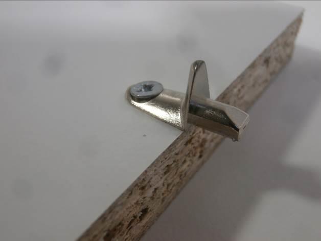
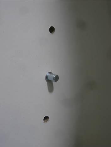
33 Strona age: 33 otografia / hoto 5 Construction details otografia / hoto 6 Construction details otografia / hoto 7 Construction details otografia / hoto 8 Construction details otografia / hoto 9 Construction details otografia / hoto 10 Construction details


34 Strona age: 34 otografia / hoto 11 Construction details otografia / hoto 12 Marking otografia / hoto 13 Mechanical testing otografia / hoto 14 Mechanical testing otografia / hoto 15 Mechanical testing otografia / hoto 16 Mechanical testing


35 Strona age: 35 otografia / hoto 17 Mechanical testing otografia / hoto 18 Mechanical testing Koniec raportu End
DELTIM Sp. z o.o. S.K.A ul. Rząsawska 30/38; Częstochowa. Bumper bar X-Lander X-Move
 Strona Page: 1 Zleceniodawca: Client: DELTIM Sp. z o.o. S.K.A ul. Rząsawska 30/38; 42-209 Częstochowa Przedmiot badania: Test item: Bumper bar X-Lander X-Move Producent / Klient zew.: Manufacturer / ext.
099 Łóżko półpiętrowe 2080x1010(1109)x Bunk bed 2080x1010(1109)x1600 W15 INSTRUKCJA MONTAŻU ASSEMBLY INSTRUCTION
x Bunk bed 2080x1010(1109)x1600 W15 INSTRUKCJA MONTAŻU ASSEMBLY INSTRUCTION") INSTRUKCJA MONTAŻU ASSEMBLY INSTRUCTION 2 WAŻNE, ZACHOWAĆ DO PÓŹNIEJSZEGO STOSOWANIA- UWAŻNIE PRZECZYTAĆ IMPORTANT, SAVE FOR FURTHER USAGE- READ CAREFULLY INSTRUKCJA UZYTKOWANIA USER S MANUAL. Aby uniknąć
INSTRUKCJA MONTAŻU ASSEMBLY INSTRUCTION 2 WAŻNE, ZACHOWAĆ DO PÓŹNIEJSZEGO STOSOWANIA- UWAŻNIE PRZECZYTAĆ IMPORTANT, SAVE FOR FURTHER USAGE- READ CAREFULLY INSTRUKCJA UZYTKOWANIA USER S MANUAL. Aby uniknąć
098 Łóżko piętrowe 2080x1010(1109)x Double bunk bed 2080x1010(1109)x1600 W15 MONTAGEANLEITUNG ASSEMBLY INSTRUCTION
x Double bunk bed 2080x1010(1109)x1600 W15 MONTAGEANLEITUNG ASSEMBLY INSTRUCTION") 098 Double bunk bed 2080x(9)x600 W5 MONTAGEANLEITUNG ASSEMBLY INSTRUCTION 2 WAŻNE, ZACHOWAĆ DO PÓŹNIEJSZEGO STOSOWANIA- UWAŻNIE PRZECZYTAĆ IMPORTANT, SAVE FOR FURTHER USAGE- READ CAREFULLY INSTRUKCJA UZYTKOWANIA
098 Double bunk bed 2080x(9)x600 W5 MONTAGEANLEITUNG ASSEMBLY INSTRUCTION 2 WAŻNE, ZACHOWAĆ DO PÓŹNIEJSZEGO STOSOWANIA- UWAŻNIE PRZECZYTAĆ IMPORTANT, SAVE FOR FURTHER USAGE- READ CAREFULLY INSTRUKCJA UZYTKOWANIA
DO MONTAŻU POTRZEBNE SĄ DWIE OSOBY! INSTALLATION REQUIRES TWO PEOPLE!
 1 HAPPY ANIMALS B09 INSTRUKCJA MONTAŻU ASSEMBLY INSTRUCTIONS Akcesoria / Fittings K1 M M1 ZM1 Z T G1 17 szt. / pcs 13 szt. / pcs B1 13 szt. / pcs W4 13 szt. / pcs W6 14 szt. / pcs U1 1 szt. / pcs U N1
HAPPY K04 INSTRUKCJA MONTAŻU ASSEMBLY INSTRUCTIONS DO MONTAŻU POTRZEBNE SĄ DWIE OSOBY! INSTALLATION REQUIRES TWO PEOPLE! W5 W6 G1 T2 U1 U2 TZ1
 HAPPY K0 INSTRUKCJA MONTAŻU ASSEMBLY INSTRUCTIONS W Akcesoria / Fittings W W G K szt. / pcs M Ø Ø 0 Ø, Ø Ø. 0 ø8 M 8 szt. / pcs 0 szt. / pcs szt. / pcs T U U szt. / pcs szt. / pcs szt. / pcs S TZ szt.
DO MONTAŻU POTRZEBNE SĄ DWIE OSOBY! INSTALLATION REQUIRES TWO PEOPLE!
 HAPPY ANIMALS RW08 INSTRUKCJA MONTAŻU ASSEMBLY INSTRUCTIONS Akcesoria / Fittings K M M ZM ZW G 0 szt. / pcs W szt. / pcs B szt. / pcs szt. / pcs W U 8 szt. / pcs 4 szt. / pcs U N szt. / pcs Ø3 x szt. /
DO MONTAŻU POTRZEBNE SĄ DWIE OSOBY! INSTALLATION REQUIRES TWO PEOPLE!
 1 HAPPY ANIMALS SZ11 A INSTRUKCJA MONTAŻU ASSEMBLY INSTRUCTIONS Akcesoria / Fittings K1 M M1 ZM1 Z G1 szt. / pcs 0 szt. / pcs B1 6 szt. / pcs 6 szt. / pcs W6 0 szt. / pcs U1 19 szt. / pcs U 50 szt. / pcs
/2016. Hangsen Spółka z o.o. ul. Siemianowicka 98, Bytom. Hangsen Spółka z o.o. ul. Siemianowicka 98, Bytom
 Strona Page: 1 Zleceniodawca: Client: Hangsen Spółka z o.o. ul. Siemianowicka 98, 41-902 Bytom Przedmiot badania: Test item: E-liquid packages Producent / Klient zew.: Manufacturer / ext. Customer: Hangsen
HAPPY ANIMALS L01 HAPPY ANIMALS L03 HAPPY ANIMALS L05 HAPPY ANIMALS L07
 HAPPY ANIMALS L0 HAPPY ANIMALS L0 HAPPY ANIMALS L0 HAPPY ANIMALS L07 INSTRUKCJA MONTAŻU ASSEMBLY INSTRUCTIONS Akcesoria / Fittings K ZW W8 W7 Ø x 6 szt. / pcs Ø7 x 70 Narzędzia / Tools DO MONTAŻU POTRZEBNE
HAPPY ANIMALS L02 HAPPY ANIMALS L04 HAPPY ANIMALS L06 HAPPY ANIMALS L08
 HAPPY ANIMALS L02 HAPPY ANIMALS L04 HAPPY ANIMALS L06 HAPPY ANIMALS L08 INSTRUKCJA MONTAŻU ASSEMBLY INSTRUCTIONS Akcesoria / Fittings K O G ZW W8 W4 20 szt. / pcs 4 szt. / pcs 4 szt. / pcs 4 szt. / pcs
 www.irs.gov/form990. If "Yes," complete Schedule A Schedule B, Schedule of Contributors If "Yes," complete Schedule C, Part I If "Yes," complete Schedule C, Part II If "Yes," complete Schedule C, Part
 www.irs.gov/form990. If "Yes," complete Schedule A Schedule B, Schedule of Contributors If "Yes," complete Schedule C, Part I If "Yes," complete Schedule C, Part II If "Yes," complete Schedule C, Part
/2011. PPUH FRISTOM Tomasz Frieske ul. Byszewska 54a, Bydgoszcz, Poland. Optical-electric part of LED working lamp
 Zał. nr 4 O-TÜV-2 Strona age: 1 Stron ages: 6 Zleceniodawca: Client: rzedmiot badania: Test item: roducent / Klient zew.: Manufacturer / ext. Customer: UH RISTOM Tomasz rieske ul. Byszewska 54a, 85-416
HOWE A/S, Filosofgangen 18, 5000 Odense C. HOWE A/S, Filosofgangen 18, 5000 Odense C. BIFMA X Sections: 4.3, 5.2, 5.3, 5.4, 5.
 Zał. nr 4 O-TÜV-2 Strona age: 1 Stron ages: 21 Zleceniodawca: Client: HOWE A/S, ilosofgangen 18, 5000 Odense C rzedmiot badania: Test item: SIMLA Bar Height roducent / Klient zew.: Manufacturer / ext.
 www.irs.gov/form990. If "Yes," complete Schedule A Schedule B, Schedule of Contributors If "Yes," complete Schedule C, Part I If "Yes," complete Schedule C, Part II If "Yes," complete Schedule C, Part
EN 15372:2016 BIFMA X Sections: 4.3, 5.2, 5.3, 5.4, 5.5, 6, 7
 Zał. nr 4 O-TÜV-2 Strona age: 1 Stron ages: 26 Zleceniodawca: Client: HOWE L sp. z o. o., Ul. Wyspiańskiego 26B/5, 60-751 oznań rzedmiot badania: Test item: SIMLA fold table roducent / Klient zew.: Manufacturer
TR18 INSTALATION MANUAL / INSTRUKCJA MONTAŻU. cart for flat displays
 INSTLTION NUL / INSTRUKCJ ONTŻU cart for flat displays WRNING: Please read this manual before the installation to ensure proper assembly. The assembly should be carried out in accordance with this manual
G14L LPG toroidal tank
 G14L LPG toroidal tank Product Description 4-hole version of the unique STAKO patented design of the full (centre-filled) toroidal tank. The valve plate enhances the functionality of the tank compared
POL-POWER Sp. z o.o. ul. Poznańska 113A, Komorniki. TÜV Rheinland Polska Sp. z o.o. ul. Lutycka 11, Poznań
 Zał. nr 4 O-TÜV-2 Strona age: 1 Stron ages: 34 Zleceniodawca: Client: OL-OWER Sp. z o.o. ul. oznańska 113A, 62-052 Komorniki rzedmiot badania: Test item: Łóżeczka dziecięce mieszkaniowe Children's cot
 !850016! www.irs.gov/form8879eo. e-file www.irs.gov/form990. If "Yes," complete Schedule A Schedule B, Schedule of Contributors If "Yes," complete Schedule C, Part I If "Yes," complete Schedule C,
1113NG 487. Importer. Assembly Instructions. Instrukcja Montażu 66 GEYZ
 1113NG 487 Importer www.ogrodosfera.pl Assembly Instructions Instrukcja Montażu 66 GEYZ 1 2 3 ASSEMBLY INSTRUCTIONS (ENGLISH). Before starting, read through the assembly instructions carefully. Check thoroughly
 www.irs.gov/form990. If "Yes," complete Schedule A Schedule B, Schedule of Contributors If "Yes," complete Schedule C, Part I If "Yes," complete Schedule C, Part II If "Yes," complete Schedule C, Part
Instrukcja obsługi. binding machine KRIS. instruction manual. 80-393 GDAŃSK ul. Krynicka 1 tel.: (058) 55 43 555 fax: (058) 55 43 500 ODDZIAŁ:
 55 43 555 fax: (058) 55 43 500 ODDZIAŁ:") Instrukcja obsługi instruction manual 80-393 GDAŃSK ul. Krynicka 1 tel.: (058) 55 43 555 fax: (058) 55 43 500 ODDZIAŁ: 02-784 WARSZAWA ul. Janowskiego 9 tel.: (022) 648 03 48..49 fax: (022) 648 03 50 bindownica
Instrukcja obsługi instruction manual 80-393 GDAŃSK ul. Krynicka 1 tel.: (058) 55 43 555 fax: (058) 55 43 500 ODDZIAŁ: 02-784 WARSZAWA ul. Janowskiego 9 tel.: (022) 648 03 48..49 fax: (022) 648 03 50 bindownica
SSW1.1, HFW Fry #20, Zeno #25 Benchmark: Qtr.1. Fry #65, Zeno #67. like
 SSW1.1, HFW Fry #20, Zeno #25 Benchmark: Qtr.1 I SSW1.1, HFW Fry #65, Zeno #67 Benchmark: Qtr.1 like SSW1.2, HFW Fry #47, Zeno #59 Benchmark: Qtr.1 do SSW1.2, HFW Fry #5, Zeno #4 Benchmark: Qtr.1 to SSW1.2,
OBWIESZCZENIE MINISTRA INFRASTRUKTURY. z dnia 18 kwietnia 2005 r.
 OBWIESZCZENIE MINISTRA INFRASTRUKTURY z dnia 18 kwietnia 2005 r. w sprawie wejścia w życie umowy wielostronnej M 163 zawartej na podstawie Umowy europejskiej dotyczącej międzynarodowego przewozu drogowego
Zwora Yale US06. Yale seria US kg. Zastosowanie. Właściwości. Parametry techniczne
 Zwora Yale US06 Yale seria US06 270 kg Zastosowanie Zwory serii US06 przeznaczone są do realizowania kontroli dostępu w pomieszczeniach wymagających podstawowej ochrony np. drzwi wewnętrzne. Właściwości
 www.irs.gov/form990. If "Yes," complete Schedule A Schedule B, Schedule of Contributors If "Yes," complete Schedule C, Part I If "Yes," complete Schedule C, Part II If "Yes," complete Schedule C, Part
60 OPTOTECHNIKA BELINTRA STORAGE I MODULAR CABINETS MAGAZYNOWANIE I SZAFY MODUŁOWE MODULAR CABINETS SZAFY MODUŁOWE
 MODULAR CABINETS Modular cabinet system, mainly for the closed storage of closed containers and baskets. SZAFY MODUŁOWE Szafy modułowe do zamkniętego magazynowania koszy i tac. MODULAR CABINETS. CLOSED
Installation of EuroCert software for qualified electronic signature
 Installation of EuroCert software for qualified electronic signature for Microsoft Windows systems Warsaw 28.08.2019 Content 1. Downloading and running the software for the e-signature... 3 a) Installer
TECHNICAL CATALOGUE WHITEHEART MALLEABLE CAST IRON FITTINGS EE
 TECHNICAL CATALOGUE WHITEHEART MALLEABLE CAST IRON FITTINGS EE Poland GENERAL INFORMATION USE Whiteheart malleable cast iron fittings brand EE are used in threaded pipe joints, particularly in water, gas,
DM-ML, DM-FL. Auxiliary Equipment and Accessories. Damper Drives. Dimensions. Descritpion
 DM-ML, DM-FL Descritpion DM-ML and DM-FL actuators are designed for driving round dampers and square multi-blade dampers. Example identification Product code: DM-FL-5-2 voltage Dimensions DM-ML-6 DM-ML-8
BLACKLIGHT SPOT 400W F
 BLACKLIGHT SPOT 400W F2000339 USER MANUAL / INSTRUKCJA OBSŁUGI BLACKLIGHT SPOT 400W F2000339 Table of Contents 1 Introduction... 2 2 Safety information... 2 3 Product information... 2 3.1 Specification...
Obudowa betonowa do wkładu kominkowego Blanka 8 kw. Instrukcja obsługi i karta gwarancyjna ver. 2
 Obudowa betonowa do wkładu kominkowego Blanka 8 kw Instrukcja obsługi i karta gwarancyjna ver. 2 (PL) The concrete casing for fireplace insert Blanka 8 kw User Manual and Warranty Card (EN) Obudowa betonowa
LED WASHER 30x3W WHITE IP65 F
 USER MANUAL / INSTRUKCJA OBSŁUGI LED WASHER 30x3W WHITE IP65 F7200171 LED WASHER 30x3W WHITE IP65 F7200171 Table of contents 1 Introduction... 2 2 Safety information... 2 3 Product information... 2 3.1
Zasady bezpieczeństwa
 2 3 Zasady bezpieczeństwa GB The door and the feeding flap must be closed when operating the machine! PL Drzwiczki i klapka szczeliny podawczej muszą być zamknięte w trakcie używania urządzenia! GB Ensure
Robotic Arm Assembly Manual
 Robotic Arm Assembly Manual 1. List of materials 3D printed Parts: Part Quantity Arm 1 gear.stl 1 Arm 1 lower.stl 1 Arm 1 upper.stl 1 Arm 2.STL 1 Arm 3.STL 1 Base gear.stl 1 Base.STL 1 Grasper 1.STL 1
Pokrywa kołnierza ø120 z tuleją 1½ oraz ø180 z tuleją 2. Flange Cover ø120 with 1 ½ Sleeve and ø180 with 2 Sleeve. Instrukcja montażu
 Pokrywa kołnierza ø0 z tuleją ½ oraz ø80 z tuleją Instrukcja montażu Flange Cover ø0 with ½ Sleeve and ø80 with Sleeve Installation Manual 5.0.06 576 INSTRUKCJA MONTAŻU Spis treści PL. INFORMACJE OGÓLNE....
Tłumaczenie oryginalnej deklaracji ( z języka angielskiego)
") Tłumaczenie oryginalnej deklaracji ( z języka angielskiego) Deklaracja zgodności CE SOLER & PALAU Sistemas de Ventilacion S.L.U. C/Llevant 4 08150 Parets del Valles (Hiszpania) Deklaruje, że wentylator
Tłumaczenie oryginalnej deklaracji ( z języka angielskiego) Deklaracja zgodności CE SOLER & PALAU Sistemas de Ventilacion S.L.U. C/Llevant 4 08150 Parets del Valles (Hiszpania) Deklaruje, że wentylator
Helena Boguta, klasa 8W, rok szkolny 2018/2019
 Poniższy zbiór zadań został wykonany w ramach projektu Mazowiecki program stypendialny dla uczniów szczególnie uzdolnionych - najlepsza inwestycja w człowieka w roku szkolnym 2018/2019. Składają się na
 www.irs.gov/form8879eo. e-file www.irs.gov/form990. If "Yes," complete Schedule A Schedule B, Schedule of Contributors If "Yes," complete Schedule C, Part I If "Yes," complete Schedule C, Part II If "Yes,"
Lecture 18 Review for Exam 1
 Spring, 2019 ME 323 Mechanics of Materials Lecture 18 Review for Exam 1 Reading assignment: HW1-HW5 News: Ready for the exam? Instructor: Prof. Marcial Gonzalez Announcements Exam 1 - Wednesday February
Instrukcja obsługi. ibind A8/A12/A15/A20. instruction manual. 80-393 GDAŃSK ul. Krynicka 1 tel.: (058) 55 43 555 fax: (058) 55 43 500
 55 43 555 fax: (058) 55 43 500") Instrukcja obsługi instruction manual 80-9 GDAŃSK ul. Krynicka tel.: (08) fax: (08) 00 ODDZIAŁ: 0-78 WARSZAWA ul. Janowskiego 9 tel.: (0) 8 0 8..9 fax: (0) 8 0 0 BindownicE ibind A8/A/A/A0 BINDING MACHINEs
Instrukcja obsługi instruction manual 80-9 GDAŃSK ul. Krynicka tel.: (08) fax: (08) 00 ODDZIAŁ: 0-78 WARSZAWA ul. Janowskiego 9 tel.: (0) 8 0 8..9 fax: (0) 8 0 0 BindownicE ibind A8/A/A/A0 BINDING MACHINEs
Raport bieżący: 44/2018 Data: g. 21:03 Skrócona nazwa emitenta: SERINUS ENERGY plc
 Raport bieżący: 44/2018 Data: 2018-05-23 g. 21:03 Skrócona nazwa emitenta: SERINUS ENERGY plc Temat: Zawiadomienie o zmianie udziału w ogólnej liczbie głosów w Serinus Energy plc Podstawa prawna: Inne
Weronika Mysliwiec, klasa 8W, rok szkolny 2018/2019
 Poniższy zbiór zadań został wykonany w ramach projektu Mazowiecki program stypendialny dla uczniów szczególnie uzdolnionych - najlepsza inwestycja w człowieka w roku szkolnym 2018/2019. Tresci zadań rozwiązanych
Rodzaj obliczeń. Data Nazwa klienta Ref. Napędy z pasami klinowymi normalnoprofilowymi i wąskoprofilowymi 4/16/ :53:55 PM
 Rodzaj obliczeń Data Nazwa klienta Ref Napędy z pasami klinowymi normalnoprofilowymi i wąskoprofilowymi 4/16/2007 10:53:55 PM Rodzaj obciążenia, parametry pracy Calculation Units SI Units (N, mm, kw...)
Jazz EB207S is a slim, compact and outstanding looking SATA to USB 2.0 HDD enclosure. The case is
 1. Introduction Jazz EB207S is a slim, compact and outstanding looking SATA to USB 2.0 HDD enclosure. The case is made of aluminum and steel mesh as one of the coolest enclosures available. It s also small
D e s i g n e d b y L e c h B o n a r
 D e s i g n e d b y L e c h B o n a r Opis techniczny systemu Binar 1.Regały Regały systemu Binar zostały wykonane z płyty wiórowej o grubości 18 mm, pokrytej melaminą i wykończone taśmą brzegową ABS
DELTA 600 corner left with TÜV certi ed
 DELTA 600 corner left with TÜV certi ed DELTA/L/600/TUV Price: 1 03 EAN: 5903950175383 Horizontal, corner bio replace open on the left side is an ideal solution for tting in the nook. Shipping in package
DELTA 600 corner right with TÜV certi ed
 DELTA 600 corner right with TÜV certi ed DELTA/P/600/TUV Price: 1 03 EAN: 5903950175420 Horizontal, corner bio replace open on the right side is an ideal solution for tting in the nook. Shipping in package
Inquiry Form for Magnets
 Inquiry Form for Magnets Required scope of delivery: Yes No - Cross-beams - Magnets - Supply and Control System - Emergency supply system, backup time min - Cable drum with cable - Plug-in connections
Oprawa / Fixture BOXSET. miejsce na aranżację lub grafike z zastosowaniem, Podstawowe elementy oprawy / Basic fixture components. www.klusdesign.
 Oprawa / Fixture BOXSET miejsce na aranżację lub grafike z zastosowaniem, Podstawowe elementy oprawy / Basic fixture components 9 1 8 2 3a 4a 5 6 4b 3b 7 1. Profil BOX-Z / BOX-Z Extrusion 2. Klucz imbusowy
Wykaz linii kolejowych, które są wyposażone w urządzenia systemu ETCS
 Wykaz kolejowych, które są wyposażone w urządzenia W tablicy znajdującej się na kolejnych stronach tego załącznika zastosowano następujące oznaczenia: - numer kolejowej według instrukcji Wykaz Id-12 (D-29).
Instrukcja obsługi User s manual
 Instrukcja obsługi User s manual Konfigurator Lanberg Lanberg Configurator E-mail: support@lanberg.pl support@lanberg.eu www.lanberg.pl www.lanberg.eu Lanberg 2015-2018 WERSJA VERSION: 2018/11 Instrukcja
INSTRUKCJA OBSŁUGI OPERATIONAL MANUAL KRZESEŁKO / HIGH CHAIR MINI WYPRODUKOWANO ZGODNIE Z NORMĄ PN-EN 14988
 PL INSTRUKCJA OBSŁUGI OPERATIONAL AL MANUAL KRZESEŁKO / HIGH CHAIR MINI WYPRODUKOWANO ZGODNIE Z NORMĄ PN-EN 14988 A B C D E F G PL WAŻNE! ZACHOWAĆ W CELU POWOŁANIA SIĘ W PRZYSZŁOŚCI! OSTRZEŻENIA Nieprzestrzeganie
Wykaz linii kolejowych, które są wyposażone w urzadzenia systemu ETCS
 Wykaz kolejowych, które są wyposażone w urzadzenia W tablicy znajdującej się na kolejnych stronach tego załącznika zastosowano następujące oznaczenia: - numer kolejowej według instrukcji Wykaz Id-12 (D-29).
Rozpoznawanie twarzy metodą PCA Michał Bereta 1. Testowanie statystycznej istotności różnic między jakością klasyfikatorów
 Rozpoznawanie twarzy metodą PCA Michał Bereta www.michalbereta.pl 1. Testowanie statystycznej istotności różnic między jakością klasyfikatorów Wiemy, że możemy porównywad klasyfikatory np. za pomocą kroswalidacji.
Selfie Monopod MA426. Instrukcja obsługi User s Manual
 Selfie Monopod MA426 Instrukcja obsługi User s Manual PL Selfie Monopod Przeczytaj wszystkie instrukcje przed użyciem oraz zachowaj te informacje do wykorzystania w przyszłości. Zestaw: 1x mobile phone
European Crime Prevention Award (ECPA) Annex I - new version 2014
 Annex I - new version 2014") European Crime Prevention Award (ECPA) Annex I - new version 2014 Załącznik nr 1 General information (Informacje ogólne) 1. Please specify your country. (Kraj pochodzenia:) 2. Is this your country s ECPA
European Crime Prevention Award (ECPA) Annex I - new version 2014 Załącznik nr 1 General information (Informacje ogólne) 1. Please specify your country. (Kraj pochodzenia:) 2. Is this your country s ECPA
STANLUX SLX DO ŚCIANY STANLUX SLX TO THE WALL
 STANLUX SLX DO ŚCIANY STANLUX SLX TO THE WALL z samodomykaczem z okuciem SLX z prowadnikiem dolnym mocowanym do ściany with soft-closer with SLX hardware with lower guide fastestened to the wall 100 18-40
Camspot 4.4 Camspot 4.5
 User manual (addition) Dodatek do instrukcji obsługi Camspot 4.4 Camspot 4.5 1. WiFi configuration 2. Configuration of sending pictures to e-mail/ftp after motion detection 1. Konfiguracja WiFi 2. Konfiguracja
LEARNING AGREEMENT FOR STUDIES
 LEARNING AGREEMENT FOR STUDIES The Student First and last name(s) Nationality E-mail Academic year 2014/2015 Study period 1 st semester 2 nd semester Study cycle Bachelor Master Doctoral Subject area,
Jøtul I 570 FL. Szyba / Glass. Jøtul I 570 FL. Art.no. TS39B002. PL - Instrukcja montażu dodatkowej szyby 2 GB - Installation Instructions 4
 Jøtul I 570 FL Szyba / Glass Jøtul I 570 FL PL - Instrukcja montażu dodatkowej szyby 2 G - Installation Instructions 4 rt.no. TS39002 PL - Przed użyciem prosimy dokładnie przeczytać instrukcje ogólnego
TURNTABLES OBROTNICE 1
 1 TURNTABLES OBROTNICE TURNTABLES have been created to further increase the efficiency of exchanging containers. These devices are installed next to production sections so that material can be delivered
Typ VME FOR THE MEASUREMENT OF VOLUME FLOW RATES IN DUCTS
 Typ VME FOR THE MEASUREMENT OF VOLUME FLOW RATES IN DUCTS Rectangular volume flow rate measuring units for the recording or monitoring of volume flow rates Manual volume flow rate measuring Permanent volume
User Manual Instrukcja obsługi
 www.twistcar.eu User Manual Instrukcja obsługi KKS Jakub Sadowski Sp. J. Łowicka 51/23A 02-535 Warszawa, Poland biuro@twistcar.eu Pojazd dziecięcy Twist-ball Dziękujemy za zakup pojazdu dziecięcego Twist-ball.
Surname. Other Names. For Examiner s Use Centre Number. Candidate Number. Candidate Signature
 A Surname _ Other Names For Examiner s Use Centre Number Candidate Number Candidate Signature Polish Unit 1 PLSH1 General Certificate of Education Advanced Subsidiary Examination June 2014 Reading and
VENEZIA BOXES DO KABIN PRYSZNICOWYCH SHOWER. Zawiasy i klamry do kabin prysznicowych Shower hinges and clamps AKCESORIA ACCESSORIES
 Zawiasy i klamry do kabin prysznicowych Shower hinges and clamps AKCESORIA DO KABIN PRYSZNICOWYCH SHOWER BOXES ACCESSORIES AKCESORIA DO SZKŁA HARTOWANEGO ZAWIASY SERIA TGAH 800 Z REGULACJĄ KĄTA ADJUSTABLE
Strona główna > Produkty > Filtry i wkłady filtracyjne > Obudowy filtrów do montażu kanałowego > Spigots > Typ KSFSSP. Typ KSFSSP
 Typ KSFSSP FOR FILTER UNIT SYSTEMS WITH HORIZONTAL AIR ENTRY AND OUTLET Spigot for assembling filter unit systems in ductwork Spigots made of sheet steel with decontaminable powder coating RAL 9010 Air
SYSTEMY NAWIERZCHNIOWE DO SZAF SURFACE TYPE SYSTEMS FOR WARDROBES SUPERIOR. w trzech wariantach in three versions
 SYSTEMY NAWIERZCHNIOWE DO SZAF SURFACE TYPE SYSTEMS FOR WARDROBES SUPERIOR w trzech wariantach in three versions SYSTEMY NAWIERZCHNIOWE DO SZAF SURFACE TYPE SYSTEMS FOR WARDROBES SUPERIOR w trzech wariantach
Zmiany techniczne wprowadzone w wersji Comarch ERP Altum
 Zmiany techniczne wprowadzone w wersji 2018.2 Copyright 2016 COMARCH SA Wszelkie prawa zastrzeżone Nieautoryzowane rozpowszechnianie całości lub fragmentu niniejszej publikacji w jakiejkolwiek postaci
WYKAZ PRÓB / SUMMARY OF TESTS. mgr ing. Janusz Bandel
 Sprawozdanie z Badań Nr Strona/Page 2/24 WYKAZ PRÓB / SUMMARY OF TESTS STRONA PAGE Próba uszkodzenia przy przepięciach dorywczych TOV failure test 5 Próby wykonał / The tests were carried out by: mgr ing.
Uszczelnianie profili firmy KLUŚ na przykładzie profilu PDS 4 - ALU / Sealing KLUŚ profiles on example of PDS 4 - ALU profile. Pasek LED / LED strip
 Uszczelnianie profili firmy KLUŚ na przykładzie profilu PDS 4 - ALU / Sealing KLUŚ profiles on example of PDS 4 - ALU profile. 1. Pasek LED / LED strip Rękaw termokurczliwy / heat shrink sleeve Istnieje
For choosen profiles, KLUS company offers end caps with holes for leading power supply cable. It is also possible to drill the end cap independently
 Uszczelnianie profili firmy KLUŚ na przykładzie profilu PDS 4 - ALU / Sealing KLUŚ profiles on example of PDS 4 - ALU profile. 1. Pasek LED / LED strip Rękaw termokurczliwy / heat shrink sleeve Istnieje
OPRAWY I CZÊŒCI ZNORMALIZOWANE DO T OCZNIKÓW
 FCPK a SUPERIOR DIE SET CORPORATION COMPANY FCPK Bytów Sp. z o.o. ul. Lêborska 26, 77-100 Bytów, Poland tel. +48-59-822-9700, fax +48-59-822-9701 www.fcpk.pl OPRAWY I CZÊŒCI ZNORMALIZOWANE DO T OCZNIKÓW
Zakopane, plan miasta: Skala ok. 1: = City map (Polish Edition)
") Zakopane, plan miasta: Skala ok. 1:15 000 = City map (Polish Edition) Click here if your download doesn"t start automatically Zakopane, plan miasta: Skala ok. 1:15 000 = City map (Polish Edition) Zakopane,
Zakopane, plan miasta: Skala ok. 1:15 000 = City map (Polish Edition) Click here if your download doesn"t start automatically Zakopane, plan miasta: Skala ok. 1:15 000 = City map (Polish Edition) Zakopane,
spełnia wymagania Dyrektywy Niskonapięciowej 2006/95/EC, w oparciu o następujące normy zharmonizowane
 Tłumaczenie oryginalnej deklaracji ( z języka angielskiego) Deklaracja Zgodności WE Producent C/Llevant, 4 08150-Parets del Vallès-Barcelona oświadcza, że produkt opisany poniżej CYLINDRICAL CASED AXIAL
BN1520 BN1521 BN1522 FAMOR S.A. ROZDZIELNICA ŒWIATE NAWIGACYJNYCH I SYGNALIZACYJNYCH NAVIGATION AND SIGNAL LIGHT CONTROL PANELS EDITION 07/04
 EDITION 07/04 ROZDZIELNICA ŒWIATE NAWIGACYJNYCH I SYGNALIZACYJNYCH BN1520 BN1521 BN1522 Rozdzielnica BN1520-8 latarñ BN1520-8-way panel Rozdzielnica BN1520-12 latarñ BN1520-12-way panel Rozdzielnica BN1521-13
EXAMPLES OF CABRI GEOMETRE II APPLICATION IN GEOMETRIC SCIENTIFIC RESEARCH
 Anna BŁACH Centre of Geometry and Engineering Graphics Silesian University of Technology in Gliwice EXAMPLES OF CABRI GEOMETRE II APPLICATION IN GEOMETRIC SCIENTIFIC RESEARCH Introduction Computer techniques
OpenPoland.net API Documentation
 OpenPoland.net API Documentation Release 1.0 Michał Gryczka July 11, 2014 Contents 1 REST API tokens: 3 1.1 How to get a token............................................ 3 2 REST API : search for assets
TURNTABLES Turntables have been created to further increase the efficiency of exchanging containers. These devices are installed next
 TURNTABLES TURNTABLES Turntables have been created to further increase the efficiency of echanging containers. These devices are installed net to production sections so that material can be delivered safely
311186J. Copyright 2004, Graco Inc. is registered to I.S. EN ISO 9001
 311186J Copyright 2004, Graco Inc. is registered to I.S. EN ISO 9001 2 3 4 5 6 7 8 9 10 11 12 13 14 15 16 17 18 19 20 21 Graco warrants all equipment referenced in this document which is manufactured by
LS-082. System podnoszenia szyb pojedyńczych i zespolonych. Professional lift up opening for flat linear glasses System LS-082 02.
 LS-082 Professional lift up opening for flat linear glasses System LS-082 System podnoszenia szyb pojedyńczych i zespolonych 02.20 LS-082/01 0 600 (Max) 0 47 1000 1016 749 (Max) 785 16 47 8 8 50 Lw/Lt LS-082.0021
Typ TFP FOR CRITICAL AIR CLEANLINESS AND VERY CRITICAL HYGIENE REQUIREMENTS, SUITABLE FOR CEILING INSTALLATION
 Typ TFP FOR CRITICAL AIR CLEANLINESS AND VERY CRITICAL HYGIENE REQUIREMENTS, SUITABLE FOR CEILING INSTALLATION Pharmaceutical clean room terminal filters as final filter stage with Mini Pleat filter panels
Profile aluminiowe Systemy podnoszenia szyb do lad i witryn przeszklonych
 Profile aluminiowe Systemy podnoszenia szyb do lad i witryn przeszklonych Aluminium profiles Glass opening systems for counters and display cases www.aifo.pl A i F O GROUP 32-700 Bochnia, ul. Łany 23 POLAND
Uszczelki. Samozamykacze podłogowe Floor springs AKCESORIA DO STRUKTUR BEZRAMOWYCH ACCESSORIES FOR FRAMELESS GLASS CONSTRUCTION
 BERGAMO BUDRIO Uszczelki & FIRENZE Clip seals Samozamykacze podłogowe Floor springs AKCESORIA DO STRUKTUR BEZRAMOWYCH ACCESSORIES FOR FRAMELESS GLASS CONSTRUCTION BERGAMO TD800 Samozamykacz podłogowy Floor
Machine Learning for Data Science (CS4786) Lecture 11. Spectral Embedding + Clustering
 Lecture 11. Spectral Embedding + Clustering") Machine Learning for Data Science (CS4786) Lecture 11 Spectral Embedding + Clustering MOTIVATING EXAMPLE What can you say from this network? MOTIVATING EXAMPLE How about now? THOUGHT EXPERIMENT For each
Machine Learning for Data Science (CS4786) Lecture 11 Spectral Embedding + Clustering MOTIVATING EXAMPLE What can you say from this network? MOTIVATING EXAMPLE How about now? THOUGHT EXPERIMENT For each
DEKLARACJA WŁAŚCIWOŚCI UŻYTKOWYCH
 EN 14899-2:2006 0086 DEKLARACJA WŁAŚCIWOŚCI UŻYTKOWYCH 1. Rodzaj produktu: Niepowtarzalny kod identyfikacyjny typu wyrobu: Fibremesh 650 S 02 14 05 05 100 0 000081 2. Numer typu, partii lub serii lub jakikolwiek
WYKAZ PRÓB / SUMMARY OF TESTS
 Strona/Page 2/9 WYKAZ PRÓB / SUMMARY OF TESTS PN-EN 61643-11:2006 STRONA PAGE Próba nieusuwalności znakowania Test of indelibility of markings Próba niezawodności śrub, części przewodzących i połączeń
Nowy produkt na rynku / Product launch Opaska ogniochronna / Fire shutoff strap Typ RAB 30 Type RAB 30
 Nowy produkt na rynku / Product launch Opaska ogniochronna / Fire shutoff strap Typ RAB 30 Type RAB 30 POLTECHNIK Sp. z o.o. Sp. k. http://poltechnik.pl info@poltechnik.pl tel. 71 353 86 94 On the way
Attachment nr 2: Technical data/ Załacznik nr 2: Dane techniczny
 TECHNICAL SPECIFICATIONS Technical description for the engineering, the manufacturing, the installation, the commissioning molds for execution of Foundry molds for wheels. General scope of supply: - No.
Machine Learning for Data Science (CS4786) Lecture11. Random Projections & Canonical Correlation Analysis
 Lecture11. Random Projections & Canonical Correlation Analysis") Machine Learning for Data Science (CS4786) Lecture11 5 Random Projections & Canonical Correlation Analysis The Tall, THE FAT AND THE UGLY n X d The Tall, THE FAT AND THE UGLY d X > n X d n = n d d The
Machine Learning for Data Science (CS4786) Lecture11 5 Random Projections & Canonical Correlation Analysis The Tall, THE FAT AND THE UGLY n X d The Tall, THE FAT AND THE UGLY d X > n X d n = n d d The
LED MAGIC BALL MP3 F
 USER MANUAL / INSTRUKCJA OBSŁUGI LED MAGIC BALL MP3 F7000623 LED MAGIC BALL MP3 F7000623 Table of contents 1 Introduction... 2 2 Safety information... 2 3 Product information... 2 3.1 Specification...
Updated Action Plan received from the competent authority on 4 May 2017
 1 To ensure that the internal audits are subject to Response from the GVI: independent scrutiny as required by Article 4(6) of Regulation (EC) No 882/2004. We plan to have independent scrutiny of the Recommendation
Typ VFR. Circular flow adjustment dampers for the adjustment of volume flow rates and pressures in supply air and extract air systems
 Typ VFR FOR THE RELIABLE BALANCING OF VOLUME FLOW RATES Circular flow adjustment dampers for the adjustment of volume flow rates and pressures in supply air and extract air systems Each flow adjustment
WYŁĄCZNIK CZASOWY OUTDOOR TIMER
 003-582 PL WYŁĄCZNIK CZASOWY Instrukcja obsługi (Tłumaczenie oryginalnej instrukcji) Ważny! Przed użyciem uważnie przeczytaj instrukcję obsługi! Zachowaj ją na przyszłość. EN OUTDOOR TIMER Operating instructions
AKCESORIA DO KABIN PRYSZNICOWYCH SHOWER ENCLOSURES FITTINGS VESUVIO
 VESUVIO VESUVIO ZAWIASY I KLAMRY DO KABIN PRYSZNICOWYCH SHOWER HINGES AND CLAMPS ZAWIASY UNOSZONE TTU LIFTED HINGES TTU TTU90LH TTU90RH TTU90-OSLH TTU90-OSRH TTU10LH TTU10RH TTU90GGLH TTU90GGRH KLAMRY
DEKLARACJA WŁAŚCIWOŚCI UŻYTKOWYCH HECO-DoP_ETA_15/0784_MMS-plus_1804_PL
 DEKLARACJA WŁAŚCIWOŚCI UŻYTKOWYCH 1. Niepowtarzalny kod identyfikacyjny typu wyrobu: MULTI-MONTI-plus (MMS-plus) 2. Numer typu, partii lub serii lub jakikolwiek inny element umożliwiający identyfikację
Tychy, plan miasta: Skala 1: (Polish Edition)
") Tychy, plan miasta: Skala 1:20 000 (Polish Edition) Poland) Przedsiebiorstwo Geodezyjno-Kartograficzne (Katowice Click here if your download doesn"t start automatically Tychy, plan miasta: Skala 1:20 000
Tychy, plan miasta: Skala 1:20 000 (Polish Edition) Poland) Przedsiebiorstwo Geodezyjno-Kartograficzne (Katowice Click here if your download doesn"t start automatically Tychy, plan miasta: Skala 1:20 000