Rada Naukowa Scientific Board
|
|
|
- Amalia Góra
- 6 lat temu
- Przeglądów:
Transkrypt

1

2
3 34 / 2013 Radaktor Naczelny Editor In Chief Prof. dr hab. Kazimierz Kuśnierz Redaktorzy Tematyczni Topical Editors Dr Łukasz Bednarz (konstrukcje murowane / masonry structures), Politechnika Wrocławska Prof. dr hab. Jerzy Jasieńko (konstrukcja i konserwacja / constructions and conservation) Politechnika Wrocławska Dr hab. Hanna Kóčka-Krenz, prof. (archeologia / archaeology), Uniwersytet im. Adama Mickiewicza Prof. Andrzej Koss (konserwacja i restauracja dzieł sztuki conservation and restoration of works of art) Akademia Sztuk Pięknych w Warszawie Prof. dr hab. Czesław Miedziałowski (konstrukcja / constructions), Politechnika Białostocka Dr Tomasz Nowak (konstrukcje drewniane / timber structures), Politechnika Wrocławska Prof. dr hab. Zdzisława Tołłoczko (historia sztuki, kultury, estetyka / history of art and culture, aesthetics) Politechnika Krakowska Sekretarz Redakcji Editorial Secretary Dr Dominika Kuśnierz-Krupa wk@skz.pl Biuro Redakcji Editorial Office Mgr Jacek Rulewicz, Sekretarz Generalny SKZ Dr Maria Stępińska Warszawa, ul. Szwoleżerów 9 tel , info@skz.pl, wk@skz.pl Tłumaczenie Translation Mgr Violetta Marzec Projekt okładki Cover design Dr Dominika Kuśnierz-Krupa Dr Michał Krupa Opracowanie graficzne i DTP Graphic design and DTP Sławomir Pęczek, EDITUS, tel , Redaktor techniczny Technical Editor Zdzisław Majewski Realizacja wydawnicza Publishing Dolnośląskie Wydawnictwo Edukacyjne Wrocław, ul. Ojca Beyzyma 20/b tel./fax , Wydawca Publisher Zarząd Główny Stowarzyszenia Konserwatorów Zabytków Warszawa, ul. Szwoleżerów 9 tel , fax Nakład: 1000 egz. Edition 1000 copies Druk ukończono w 2013 r. Printed in Rada Naukowa Scientific Board Prof. dr hab. Jerzy Jasieńko Politechnika Wrocławska (Polska) przewodniczący Wrocław University of Technology (Poland) chairman Prof. Maria Teresa Bartoli Uniwersytet we Florencji (Włochy) / University of Florence (Italy) Prof. Mario Docci Uniwerstet Sapienza w Rzymie (Włochy) / Sapienza University in Rome (Italy) Prof. Wolfram Jaeger Uniwersytet w Dreźnie (Niemcy) / University of Dresden (Germany) Prof. dr hab. Andrzej Kadłuczka Politechnika Krakowska (Polska) / Cracow University of Technology (Poland) Prof. Tatiana Kirova Politechnika w Turynie, Uniwersytet Uninettuno w Rzymie (Włochy) Polytechnic University of Turin, University Uninettuno in Rome (Italy) Prof. Andrzej Koss Akademia Sztuk Pięknych w Warszawie (Polska) Academy of Fine Arts in Warsaw (Poland) Prof. dr hab. Kazimierz Kuśnierz Politechnika Krakowska (Polska) / Cracow University of Technology (Poland) Dr hab. Jadwiga Łukaszewicz, prof. Uniwersytet Mikołaja Kopernika (Polska) Nicolaus Copernicus University in Toruń (Poland) Prof. Emma Mandelli Uniwersytet we Florencji (Włochy) / University of Florence (Italy) Prof. dr hab. Czesław Miedziałowski Politechnika Białostocka (Polska) / Bialystok University of Technology (Poland) Prof. Claudio Modena Uniwersytet w Padwie (Włochy) / University of Padua (Italy) Prof. Andre de Naeyer Uniwersytet w Antwerpii (Belgia) / University of Antwerp (Belgium) Dr hab. Piotr Rapp Politechnika Poznańska (Polska) / Poznan University of Technology (Poland) Prof. Gennaro Tampone Uniwersytet we Florencji (Włochy) / University of Florence (Italy) Prof. Angelo Di Tommaso Uniwersytet w Bolonii (Włochy) / University of Bologna (Italy) Czasopismo jest wydawane drukiem w formacie A4 (wersja pierwotna) oraz w wersji elektronicznej. Na stronie internetowej dostępne są pełne wersje numerów czasopisma w formacie pdf. The Journal is printed in A4 format (original version) and in the electronic version. Full versions of the journal issues are available in the pdf format on the Internet website WIADOMOŚCI KONSERWATORSKIE 2013 dofinansowano ze środków Ministra Kultury i Dziedzictwa Narodowego. Journal of Heritage Conservation 2013 was subsidised by the Minister of Culture and National Heritage. Wiadomości Konserwatorskie są indeksowane przez BazTech Bazę danych o zawartości polskich czasopism technicznych ( Journal of Heritage Conservation are indexed by BazTech Polish Technical Journal Contents ( Instrukcje dla autorów, podstawowe zasady recenzowania publikacji oraz lista recenzentów dostępne są na stronie internetowej Instructions for authors, basic criteria for reviewing the publications and a list of reviewers are available on the Internet website Wiadomości Konserwatorskie Journal of Heritage Conservation 34/2013 3
4 Od redakcji From the Editor Oddajemy do rąk naszych Czytelników kolejny, 34 numer Wiadomości Konserwatorskich. Nasze czasopismo przechodzi w tym roku przekształcenie z półrocznika w kwartalnik. Wiąże się to ze wzrostem zapotrzebowania środowiska konserwatorskiego w kraju na informacje o pracach związanych z ochroną zabytków, a także znacznie większą aktywnością autorów publikujących prace naukowe bądź sprawozdania z badań na łamach naszego czasopisma. Jesteśmy usatysfakcjonowani faktem, że liczba artykułów aspirujących do druku jest coraz większa i że ich autorami są też młodzi naukowcy i konserwatorzy zabytków. Taki kierunek rozwoju naszego periodyku będziemy utrzymywać, choć odbywa się to kosztem bieżących informacji z życia Stowarzyszenia Konserwatorów Zabytków (które umieszczamy na naszej stronie internetowej). Wiadomości Konserwatorskie zmieniają też standardy wydawnicze, wobec niemal dwukrotnego zwiększenia objętości periodyku w bilansie rocznym przy niezmienionej dotacji MKiDN. W okresie jesiennym w naszym środowisku odbędzie się szereg wydarzeń oraz konferencji konserwatorskich. Wśród nich najważniejszym wydaje się być spotkanie w Krakowie, na Wawelu, w ramach Europejskich Dni Dziedzictwa, które jest organizowane z inicjatywy prezesa SKZ profesora Andrzeja Kadłuczki przy udziale Politechniki Krakowskiej oraz Uniwersytetu Jana Pawła II. W ramach tej uroczystości odbędzie się seminarium Stan i perspektywy ochrony dziedzictwa architektury i sztuki sakralnej w Polsce na początku XXI wieku. Zapowiedziane jest także wręczenie wysokich odznaczeń państwowych wybitnym konserwatorom zabytków (sprawozdanie z tej uroczystości przekażemy Państwu w następnym numerze WK). Należy także odnotować kolejną sesję naukową w ramach Lubuskich Spotkań z Zabytkami, która tym razem odbędzie się w kościele parafialnym pw. Świętych Apostołów Szymona i Judy Tadeusza w Kościerzynie, gdzie przedstawione zostaną wyniki badań i prac konserwatorskich przy tym znakomitym zabytku pochodzącym z XIV wieku. Bardzo interesująco zapowiada się Kongres Turystyki Kulturowej w Kotlinie Jeleniogórskiej, pod nazwą Dziedzictwo kulturowe motorem rozwoju regionu. Kongres odbędzie się na początku drugiej połowy października, a organizowany jest przez Fundację Doliny Pałaców i Ogrodów Kotliny Jeleniogórskiej, SKZ oraz Prezydenta Miasta Jelenia Góra. W imieniu organizatorów zapraszamy do Wojanowa, Łomnicy oraz Bukowca w dniach 18 i 19 października br. Życzymy Państwu przyjemnej lektury WK, przypominając, że bieżące informacje z życia SKZ zamieszczamy na naszej stronie internetowej We give our Readers the next 34 th issue of the Journal of Heritage Conservation. Our periodical is currently being converted from a semi-annual to a quarterly. It is connected with an increased demand, expressed by the conservation circles in our country, for information about work on monument protection, as well as heightened activity of authors publishing scientific theses or reports from their research in our periodical. We are highly satisfied with the fact that the number of articles aspiring for publication is constantly growing, and that their authors are also young scientists and monument conservators. We intend to maintain this trend in our development, even though it is at the cost of current news concerning the activities of the Association of Monument Conservators (which we publish on our Internet website). Journal of Heritage Conservation is also changing its publishing standard because the periodical volume has almost doubled in the annual balance, while the subsidy from the Ministry of Culture and National Heritage has remained unaltered. In the coming autumn, several events and conservation conferences will take place in our environment. Among those, the meeting in the Wawel Castle in Krakow within the European Heritage Days seems to be the most important. It is organised on the initiative of the AMC Chairman, Professor Andrzej Kadłuczka, and contributed to by the Cracow University of Technology and the University of John Paul II. The celebrations will include a seminar entitled State and perspectives for heritage protection of church art and architecture in Poland at the beginning of the 21 st century. The ceremony of awarding eminent heritage conservators is also on the agenda (a report from the ceremony will be published in the next issue of the CN). Another Scientific Session should also be noted within the Lubuskie Meetings with Monuments which, this time, will be held in the parish church of the Apostles St. Simon and Jude Thaddeus in Kościerzyna, where results of research and conservation work in this magnificent 14 th -century monument will be presented. The Congress of Culture Tourism in the Jelenia Góra Valley entitled Cultural Heritage as the Driving Force of the Region Development looks very promising. The Congress will be held in the second half of October and will be organised by the Foundation of the Jelenia Góra Valley of Palaces and Gardens, AMC and the President of the city of Jelenia Góra. On behalf of the organisers we would like to invite you to Wojanów, Łomnica and Bukowiec on 18 and 19 October this year. We wish you a pleasant reading of the CN, and would like to remind anyone interested that current information concerning the AMC is published on our Internet website Redaktor Naczelny Editor in Chief Przewodniczący Rady Naukowej Chairman of Scientific Board Kazimierz Kuśnierz Jerzy Jasieńko 4 Wiadomości Konserwatorskie Journal of Heritage Conservation 34/2013
5 SPIS TREŚCI CONTENTS NAUKA Stefan M. Holzer Analiza numeryczna łuków i sklepień 7 Alberto Cecchi Linia ciśnień w sklepieniach obciążonych pionowo 18 Matteo Bruggi, Gabriele Milani, Alberto Taliercio Projektowanie optymalnego zbrojenia włóknowego w konstrukcjach murowych poprzez optymalizację topologii 23 Ferrari Rosalba, Cocchetti Giuseppe, Rizzi Egidio Sprężysto-plastyczna analiza konstrukcji mostu Paderno d Adda (Włochy, 1889) oparta na analizie granicznej 28 A.Bossio, M. Montuori, F. Bellucci, G.P. Lignola, A. Prota, E. Cosenza, G. Manfredir Pośrednia miara stopnia korozji bazująca na rozwarciu rysy 36 Alejandra Albuerne, Martin Williams, Victoria Lawson Przewidywanie mechanizmów awarii łuków spowodowanych ruchami podłoża za pomocą metody elementów dyskretnych z wykorzystaniem metody NSCD 41 Shahira Sharaf Eldin, Fatima Fekry, Adel El Menchawy Fortece Abu Kir jako podstawa rozwoju turystyki i lokalnej społeczności 48 Dominika Kuśnierz-Krupa Jaśliska w dawnej ziemi krakowskiej w świetle mapy Miega 57 Ewa Węcławowicz-Gyurkovich Architektura emocji 63 Marek Gosztyła, Joanna Figurska-Dudek, Mateusz Łaba Zachowanie oryginalnych odkształceń obiektu jako zagadnienie konserwatorskie na przykładzie kościoła oo. Franciszkanów w Jaśle (cz. I) 72 SCIENCE Stefan M. Holzer Numerical arch and vault analysis 7 Alberto Cecchi The curve of pressure in vertically loaded arches 18 Matteo Bruggi, Gabriele Milani, Alberto Taliercio Design of the optimal fi ber reinforcement for masonry structures via topology optimization 23 Ferrari Rosalba, Cocchetti Giuseppe, Rizzi Egidio Elastoplastic structural analysis of the Paderno d Adda bridge (Italy, 1889) based on Limit Analysis 28 A.Bossio, M. Montuori, F. Bellucci, G.P. Lignola, A. Prota, E. Cosenza, G. Manfredir Indirect measure of corrosion level based on crack opening 36 Alejandra Albuerne, Martin Williams, Victoria Lawson Prediction of the failure mechanism of arches under base motion using DEM based on the NSCD method 41 Shahira Sharaf Eldin, Fatima Fekry, Adel El Menchawy Abu Qir fortresses as vital assets for tourism motivation and community development 48 Dominika Kuśnierz-Krupa Jaśliska in the former Krakow region in the light of Mieg s map 57 Ewa Węcławowicz-Gyurkovich Architecture of emotions 63 Marek Gosztyła, Joanna Figurska-Dudek, Mateusz Łaba Preserving original deformations in the object as a conservation issue on the example of the Franciscan Church in Jasło (part I) 72 Wiadomości Konserwatorskie Journal of Heritage Conservation 34/2013 5
6 SPIS TREŚCI CONTENTS Justyna Derwisz Współczesne technologie multimedialne w wirtualnej rekonstrukcji oraz prezentacji historycznych obiektów architektonicznych 82 Mariusz R. Rychter Konserwacja i badania specjalistyczne średniowiecznego kordu z Warty 92 Krzysztof Stępiński Międzynarodowy Dzień Ochrony Zabytków kwietnia 2013, Łowicz 99 Justyna Derwisz Modern multimedia technologies in virtual reconstruction and presentation of historic architecture 82 Mariusz R. Rychter Conservation and specialist examination of a medieval short sword from Warta 92 Krzysztof Stępiński International Monument Protection Day April 2013, Łowicz 99 Od Redakcji: Niniejszym prostuje się omyłkę pisarską, która pojawiła się w wersji papierowej numeru 33/2013 Wiadomości Konserwatorskich, w artykule Pani dr Klaudii Stali: s. 34, podpis pod ryc. 4, winno być: Rzut palatium wawelskiego z aneksem południowym wg K. Stali. Oprac. A. Szkiłondź, s. 37, podpis pod ryc. 3, winno być: Rekonstrukcja bryły palatium wawelskiego z przekrojem aksonometrycznym przez aulę wg Z. Pianowskiego. Źródło: J. Firlet, Z. Pianowski, Przemiany architektury rezydencji monarszej oraz katedry na Wawelu w świetle nowych badań, Kwartalnik Architektury i Urbanistyki, T. XLIV, z. 4, Wrocław Wiadomości Konserwatorskie Journal of Heritage Conservation 34/2013
7 NAUKA SCIENCE Stefan M. Holzer 1 Numerical arch and vault analysis Analiza numeryczna łuków i sklepień Key words: vaults, analytical and numerical approaches, thrust line theory, finite elements, masonry arch on spreading supports, barrel vaults, cross vaults, practical assessment Słowa kluczowe: sklepienia, podejście analityczne i numeryczne, teoria linii ciśnień, elementy skończone, łuk murowany, sklepienie kolebkowe, sklepienie krzyżowe, oszacowanie praktyczne 1. INTRODUCTION 1.1. Continuum-mechanics based approaches The oldest continuum-mechanics based approach to the numerical analysis of cracking masonry arches is due to Castigliano, 1879 [1, p ]. Castigliano analyzed the structural behaviour of Ponte Mosca, Turin (erected in 1834). He started with the assumption of a homogeneous, isotropic, elastic arch. After completing the analysis, Castigliano checked, for all radial joints, whether the joints were fully under compression or not. He assumed that the lack of tensile resistance of the mortared (or dry) joints dominates the behaviour of the masonry arch, so that the effective thickness of the arch is reduced to the height of the compressive zone (Fig. 1). In order to capture the mechanics of the arch correctly, it is therefore necessary to perform an iterative analysis. Due to the lack of tensile resistance, the centerline and the thickness of the arch change; the analysis is therefore repeated with the updated geometry, until the change to the preceding iteration is negligible. Castigliano claimed correctly that this iterative procedure would converge rapidly. Castigliano s method has found applications until very recently [2]. Castigliano s approach captures the arch mechanics in service state relatively well: The most essential characteristics of masonry, namely the anisotropy related to joint orientation, and the zero tensile strength in the direction normal to the bed joints, are represented in Castigliano s model. The main argument that can be brought forward against Castigliano s model is that it is unsuited for the analysis of the ultimate limit state: It does not permit to introduce the compressive strength of masonry. The compressed part of the arch always remains linear elastic. More recently, Castigliano s approach has been generalized into multidimensions as the NTR material model for arbitrary masonry structures ( non tensile-resistant ; see [3] for a general review and, among other contributions, [4], for specific applications to arches). This approach has been developed aiming at rigourous proofs that material models with zero tensile strength share most of the properties with more classical elastoplastic material laws (based on convex yield surfaces), and that the classical limit theorems of plasticity indeed carry over to such materials. The NTR model can be combined with any isotropic or anisotropic elastic model for the uncracked continuum. It is able to reflect the low tensile strength of masonry without any need of determining a large number of material properties. However, the main drawback of these models is that they do not take into account the orientation-dependent tensile strength of real masonry, but rather assume that masonry has no tensile strength in any direction whatsoever. While this drawback may not be so important within the scope of the analysis of masonry walls where multi-axial in-plane stress and shear dominate, it is a prohibitive drawback when one ventures to analyze vaults, because out-of-plane bending is the most important stress state for vaults. Fig. 1. The one-dimensional NTR (non tensile-resistant) model as implemented by Castigliano 1 Univ.-Prof. Dr.-Ing. Stefan M. Holzer, Institut BAU-1 (Mathematik & Bauinformatik), Universität der Bundes-wehr München, D Neubiberg, Germany, stefan.holzer@unibw.de Praca dopuszczona do druku po recenzjach Article accepted for publishing after reviews Wiadomości Konserwatorskie Journal of Heritage Conservation 34/2013 7
 employed isotropic yield surfaces with small tensile strength, more recent contributions have followed the pioneering work")
8 Conversely, classical plasticity models have also been employed in arch and vault analysis. While some older in some cases valuable contributions ([5], [6], [7], [8]) employed isotropic yield surfaces with small tensile strength, more recent contributions have followed the pioneering work of Lourenço for masonry walls (1996, [9]) in employing anisotropic failure criteria ([10], [11]) and have applied them to vaults as well. These models ensure that the vault does not prematurely crack in circumferential direction, an effect which essentially invalidated the analyses of [7], and others, and which commonly occurs when material models for concrete are carried over to the analysis of masonry vaults. Typical historical vault constructions have only one single voussoir stone in thickness direction. In such vaults, cracks follow the radial joint orientation. Circumferential cracks occur only when the tensile stiffness of the stone material is reached, which entails at the same time also the failure of the mortar in the bed joints because the cracking stone is unable to sustain the three-dimensional compressive stress state in the mortar layer. This means, as a consequence, that isotropic elastoplastic material models such as concrete models do not reflect the mechanics of historic thin vaults correctly. Anisotropic elastoplastic models, on the other hand, suffer from the fact that they cannot represent localization of strain: In other words, elastoplastic continuum models must be enriched by discontinuity models in order to capture the development of large, local cracks. Otherwise, they cannot approach the failure state of the vaults, no matter how elaborate the material model or how non-linear the geometric relations used. Furthermore, elaborate anisotropic material models require a large set of input data which are generally extremely difficult to obtain for historic vaults. The fact that the discrete, localized opening of the radial bed joints of a vault dominates the behaviour of real vaults has been highlighted by [12, p ]. This model, employing finite elements with discrete unilateral interface elements, but a simple linear elastic model for the voussoir stones, was able to produce results which captured the main effects of the vault behaviour. A similar, but more elaborate, approach has been presented more recently by [13]. This approach employs frictional interface elements. In the paper, the authors have also highlighted that the resulting model shows nonsmooth behaviour and therefore Fig. 2 A simple one-dimensional elastic-plastic opening joint model necessitates the use of advanced solvers for the path-following problem. The two studies can be viewed as a transition from the continuum model to the discontinuum models. They capture the role of the joint very well and are able to reproduce the real behaviour of historic arches. The main drawback is that they are based on an individual discretization of the voussoirs and joints and that they require two-dimensional elements for the essentially one-dimensional (curved rod) arch structure. Also, the interface elements must be carried on from the very beginning for all joints of the arch, no matter whether they acquire any importance in the actual course of the loading process. Typically, only a fraction of the joints actually open up, and only few joints reach the compressive limit. As early as 1985, Crisfield [14] has suggested an arch model based on rod elements and automatic introduction of cracking. This was achieved by a numerical integration through the thickness of the arch, taking into account a simple one-dimensional elastic-plastic material law in the direction parallel to the axis of the beam (see also Fig. 2). Crisfield s method smears the cracking effects over the element length numerically; however, this means that no discrete, localized interfaces (hinges) develop, so that the deformed figure of the arch is always a smooth curve. In reality, hinges form and the deflection curve exhibits kinks, which cannot be reproduced by smooth finite element ansatz functions. In Crisfield s numerical examples this decisive drawback was not entirely obvious because the arches studied were all shallow arches under considerable backfill. Such arches, which are characterized by high normal stresses, show a tendency towards the formation of extended plastic zones instead of localized hinges. This can also be seen in recent contributions which are based on analytical solutions, e.g. [15]: The authors have analyzed an arch under very high backfill (presumed to be an acceptable model for arched openings in walls). Their model is a simple one-dimensional elastic perfectly plastic model based on Euler-Bernoulli beam kinematics. This model, while perfectly capturing the essentials of arch mechanics, is limited in scope because only simple cases can be solved analytically. When transferred to approximate finite element analysis, it is difficult to reproduce the localizations in the deflections satisfactorily because a smooth finite element function is ill adapted to approximating a curve which exhibits sharp local changes in deflection, up to kinks. Employing low-order elements, the ultimate load-carrying capacity will be over-estimated because the smooth ansatz functions prevent the formation of hinges; conversely, high-order finite element ansatz functions will lead to oscillations and a break-down of the algorithm far before the true limit load has been reached. The localization problem of arch mechanics the formation of hinges within the general scope of an analysis with beam elements has been addressed in 1998 by Molins and Roca [Molins/Roca 1998] by a regularization based on the generation of the beam stiffness matrices by the transfer matrix method; each beam element is discretized into a number of sub-sections; the forward integration in the transfer matrix method permits arbitrary local curvature inside the beam element. The study included a one-dimensional elastic perfectly plastic material model. The only objection which can be made against this approach is that it requires a complex overall load-stepping procedure, including the storage of path information in all the interior points of the elements and is computationally burdensome because of the necessary sub-element-scale iterations. 8 Wiadomości Konserwatorskie Journal of Heritage Conservation 34/2013
9 1.2. Rigid-body approaches The complementary method to elastic, continuum-based analysis is discontinuum analysis, i.e. modeling the vault or arch as an assembly of rigid or elastic/plastic blocks with interfacial contact conditions. In the simplest case, discontinuum analysis boils down to mechanism analysis. The earliest successful attempts at mechanism analysis can be traced back far into history. The first coherent and correct solution was given in the well-known paper of Coulomb of It was Jacques Heyman s lasting contribution to bring these methods back to practice and to provide them with a modern framework by interpreting them as an application of the limit theorems of plasticity [17]. However, it can be objected against Heyman s original method that the masonry is assumed to be infinitely strong in compression, which is obviously far from true if one considers, e.g., brick vaults with thick mortar joints, a situation frequently encountered in actual historic vaults (typical compressive strength in the order of 1 2 MN/m²). A simple one-dimensional closed-form stress-strain law for masonry with cracking has been presented by [18]. This model includes as a limiting case the linear elastic perfectly plastic model, although the authors stress the fact that masonry shows a distinct falling branch in the stress-strain curve after the peak. For an extensive review of experimental data, see also [19]. Under the assumption that the elastic perfectly plastic assumption is nevertheless good enough for all practical purposes, the objection against Heyman s method was successfully tackled by Harvey and others [20] who extended Heyman s thrust line method to a method employing a thrust zone, i.e., a thrust line which is contained within a layer of finite width, corresponding to the compressive strength of the compound material. Harvey s extension to Heyman s method also removed the need to introduce a geometric factor of safety, which was required in Heyman s original approach because otherwise the stability of an arch under its own weight depends only on the form of the arch, but not on its absolute size (a natural consequence of the infinite strength assumption). Computationally, the Heyman-Harvey method is extremely efficient since it only requires a simple optimization algorithm to identify the critical hinge positions; this optimization can be performed on the basis of an arch which already exhibits three hinges, i.e., it requires only statically determined computations and therefore obviates the need for any material data except the compressive strength. The main objection against the simple hinge mechanism approaches is that they render only an estimate of the limit load, but no information on the sequence of the crack/hinge formation and on the overall loaddisplacement behaviour. The second objection that they do not include sliding mechanisms is less important. More recently, it has been shown by Ochsendorf [21] and, independently, by Jagfeld [10], that the hinge mechanism (Heyman s or Harvey s approach) approach can be easily extended to geometrically non-linear analyses; in particular, this permits reliable simulations of the problem of the arch on spreading supports, one of the most important questions in the context of assessment of real-life historic arches. In the case of spreading supports, the actual arch transforms quickly into a three-hinged system, so that the hinge mechanism method renders a sharp estimate of the actual behaviour, including the load-displacement behaviour for the arch beyond the point of the formation of the three hinges. Sliding mechanisms and combinations of hinge and sliding failure are naturally present in more general limit analysis approaches based on rigid or elastic bodies in contact with friction (the reader is referred to [22], [23], [24], [25], [26] for a review). Some of the approaches start from the static limit theorem, others from the kinematic theorem, and they render lower or upper bounds to the true collapse load, respectively. These models require an overall optimization algorithm to identify the failure mechanism. More recently, they have been successfully extended to handle complex cases such as domes, torsional action (see, e.g., [27], [28] and [29]). The most important drawback of all these approaches is that they require block-by-block modelling of the arch masonry and therefore create a great input overhead. Also, these approaches get computationally expensive if a large number of blocks are used, particularly when using elastic blocks and/or complicated constitutive laws for the interfaces. In the analysis of plane arches, sliding occurs only for very shallow geometries (e.g., the platband), or in the case of high horizontal loads, which occur naturally under seismic loading. In the assessment of typical vaults in historic buildings under static loads, sliding is typically not a major concern. 2. A SIMPLIFIED FINITE ELEMENT APPROACH In the following, we are going to develop a simplified approach for the practical analysis of masonry arches and systems of masonry piers and arches. It is based on the following ideas: beam (rod) elements are used the strength anisotropy caused by the bed joint orientation is incorporated into the model Timoshenko (shear-deformable) theory is employed, allowing the use of low shear stiffnesses for the joints the model handles the non-linearity caused by the opening of the joints under flexural stress the model is able to detect the formation of plastic hinges and incorporates discrete hinges the model incorporates the effect of limited compressive strength the model permits accuracy control by p-extension (arbitrary polynomial degree of the finite element ansatz functions). The last item in the list perhaps deserves some explanation. Typically, finite element programs for frameworks use the Euler-Bernoulli beam theory and analytical elemental matrices. This method does no longer work for non-linear stress-strain relationships (However, for an attempt to adapt a commerical finite element code to Castigliano-like analysis, but with limited compressive strength of the material, see [30]). Rather than employing the transfer matrix method for the numerical integration of the element matrices as in [16], we represent the deformation in each beam (displacements in horizontal and vertical direction, rotations) by suitable highorder polynomial approximations (see [31] for an outline of higher-order finite elements). This means that we not only have to handle unknowns at the nodes where the elements are joined, but also inside the individual elements. This approach is natural with Timoshenko beam theory, and it is easily extensible to any non-linear material law. All our computations are achieved with fi xed meshes; however, the polynomial degree of the ansatz functions inside all elements can be varied arbi- Wiadomości Konserwatorskie Journal of Heritage Conservation 34/2013 9
10 trary. p is increased until it is found that any further increase in the p level has no recognizable effect on the results. Using high p values implies the use of high-degree Gauss-Legendre quadrature schemes for the integration of the element stiffness matrices in axial direction. All the constitutive equations are evaluated at integration point level. The through-the-thickness integration, however, is performed analytically, as opposed to Crisfield s approach [14]. This implies the use of analytical stress-strain laws as explained in the present section. We start from continuum mechanics assumptions in the serviceability state: Initially, the voussoirs and the mortar are assumed to be linear elastic. Consider an arch of unit width. For given normal force N, there is a certain bending moment M which leads to opening joints. Let be the associated excentricity of the resultant of the pressures normal to the bed joints (assumed to be orthogonal to the centerline of the arch). Let t denote the thickness of the arch (cf. Fig. 1). Then, at, the joint begins to open. We denote by h t the height of the remaining compressive zone. Admitting infinite compressive stress, the maximum bending moment that can be carried by the arch for any given N is. For any excentricities, the arch is in the open joint regime (Fig. 1). In the open joint regime, the arch with plane sections and linear elastic material carries the bending moment edge of the arch is then given by. The compressive stress at the compressed. Let E denote some a serial arrangement of springs, we obtain the averaged normal stiffness of the uncracked arch approximately as This relation (and similar ones for the bending and shear stiffnesses) can be readily implemented in a finite beam element. This is essentially Castigliano s approach (except that Castigliano used (Eh) stone instead of (Et) stone, an assumption which is retrieved here if we set α = 1). This model is perfect for analysing a clamped masonry arch on rigid supports under its own weight. However, any local bending perturbation introduced by local loads on top of the arch will quickly lead to local crushing of the masonry, i.e., to the incipient formation of hinges. The same holds true for yielding supports and the resulting movement. Therefore, the model has to be extended to incorporate the crushing strength β of the masonry. The simplest possible model is the linear elastic perfectly plastic model (bilinear stress-strain relationship for compression normal to the bed joint). In elastoplastic state (cf. Fig. 2), the compressive zone of height h carries the normal force, where γh is the portion of the compressive zone in which the compressive stress has already reached the limit value β (plastic part of the section). The bending moment which can be carried under these cirumstances can be readily computed to be.. In order average Young s modulus for the masonry under compression. to obtain a dimensionless relation between bending moments and curvature again, we introduce the normal capacity N p = βt of the section under uniform pressure and the (arbitrary) reference bending moment. Now, we can write the Then, the compressive strain at the compressed edge is and the corresponding curvature of the beam is. We denote by the curvature corresponding to the dimensionless stress resultants and, and we obtain the dimensionless interaction law for combined normal and bending loads: incipient opening of the joint. Then,. This way, we. obtain the dimensionless relation between bending moment and curvature as While the joints are completely under compression, purely (linear) elastic deformation dominates. Once the joints start to open, the non-linearity caused by the opening joints becomes the most important feature. The joints are discrete gaps. Nevertheless, the effect of elastically opening joints can be smeared by simple volume averaging. Let α be the volume fraction of the mortared joints (thickness fraction of bed joints in direction parallel to the axis of the arch) and 1 α the volume fraction of the voussoir stones (in historic brick 5% α 25% vaults, typically). Then, considering the joints and the stones as. This formula describes, in the dimensionless interaction diagram, the permissible stress states of the arch under combined axial and bending action. For γ = 0, we obtain a perfectly brittle material model, whereas γ = 1 would correspond to an infinitely ductile material, permitting arbitrarily large rotations in the plastic regime. Concrete is able to accomodate ductile deformation up to γ While the dimensionless interaction diagram has already been studied by many people and has been made the startingpoint of analytical solutions (e.g., [15]), the model proposed so far is unfortunately not very suitable for incorporation into a finite element programm. The reasons for this perhaps somewhat surprising statement become evident if we use the model to derive the associated moment-curvature relation for fixed axial force. Typical historical vaults are in the range of 10 Wiadomości Konserwatorskie Journal of Heritage Conservation 34/2013
11 n For n 0.5, in the elastic perfect plastic model, the dimensi0onless curvature of the beam is given by This relation can be used to eliminate the variable γ describing the extent of plastification inside the compressive zone, yielding If this expression is inserted into the expression for the interaction between moment and axial action, we obtain, in a straighforward way, for any fixed n, a dimensionless momentcurvature relation,... Fig. 3 shows this momentcurvature relation for a fixed non-dimensional axial action n = 0.2. For comparison, the purely elastic Castigliano relationship is also shown. It is evident that the introduction of a finite compressive strength transforms the monotonically growing moment of Castigliano s model into an almost horizontal branch. arched masonry bridges with backfill, n rarely exceeds values around 0.25 even if we allow only β = 1.0 MN/m 2 for the compressive strength of the compound material mortar+stone. This observation means nothing else that the arch offers practically no further resistance to bending once it enters the plastic range. In other words, the strains will localize, a hinge forms. In order to incorporate the finite strength model into a finite element algorithm, it is therefore advisable to replace the almost horizontal part of the moment-curvature diagram by a suitable approximation. It is obvious that the most natural approximation a conservative one is given by the limiting condition when the beam reaches the compressive stress at the edge (cf. Fig. 4). The gain in moment which is associated with increasing plastification is almost negligible in practical situations. Rather than implementing an elastic-plastic law like [14], we therefore opt for introducing discrete hinges at all positions where the compressive stress reaches the strength level. In contrast to our approach, the localization of strains was effectively ruled out in [30] by setting a ductilility limit, which prevents the formation of discrete hinges (associated with ductile rotation) and forces the arch to remain continuous. Fig. 4 Simplifi ed moment-curvature relation for an elastic-perfectly plastic opening joint model Fig. 3 Moment-curvature relation for an elastic-perfectly plastic opening joint model Once part of the beam enters the elastic-plastic range, the mapping from bending moment to curvature therefore becomes almost non-unique (the slope of the curve being very small), resulting in severe problems in the context of a finite element code. In a code employing high-order trial functions, such a relation between reaction forces and deformations will automatically lead to oscillations and a premature breakdown of the algorithm, long before the actual limit load of the structure has been reached. These problems get the more severe the smaller the dimensionless normal action n is. Unfortunately, very small n is typical for most historical vaults, and even in Our procedure is incorporated in an incremental loading analysis. At each load step, the program checks for all the integration points whether the compressive stress exceeds the strength β. All these integration points are marked. In an arch with infinitely thin voussoirs, the hinge would form at the point of the maximum excessive stress in each contiguous zone of open joints. In an arch with a finite number of voussoirs, the hinge will form at the joint situated next to the peak stress. Since we control the accuracy of the finite element approximation by an increase in the polynomial degree rather than mesh refinement, it is straightforward to select a mesh in which element sizes more or less reflect voussoir sizes, and to introduce the hinges at interelement boundaries. However, this is not a prerequisite and would be impractical for very small voussoirs. Nevertheless, our program always places the hinges at interelement boundaries for simplicity. Wiadomości Konserwatorskie Journal of Heritage Conservation 34/
12 It is needless to remark that the resulting force-displacement behaviour of the arch is decidedly nonsmooth. Therefore, a classical incremental Newton-Raphson algorithm is not applicable. Rather, iterations for equilibrium are performed with a secant algorithm which always starts with the secant stiffnesses between the last equilibrated state and the origin. This means that no history information needs to be stored at element level (the whole history information being contained in the hinge locations); the additional cost caused by the linear rather than quadratic convergence of the scheme is almost negligible in practice. 3. ANALYSIS OF VARIOUS LOAD CASES Next, we proceed by applying our incremental finite element procedure to various simple cases and compare the ultimate loads obtained to the limit loads predicted by Harvey s thrust zone method. All results shown are based on a symmetric arch with an angle of embrace of 140, a centerline Fig. 5 The arch on rigid abutments under its own weight Fig. 6 The arch at 1mm horizontal yield of the right abutment (scale factor 200) Fig. 7 The arch at 2 mm horizontal yield of the right abutment (scale factor 200). Plastic hinge at apex Fig. 8 The arch at 5 mm horizontal yield of the right abutment (scale factor 200). Three-hinge state Fig. 9 Thrust-zone limit analysis of the arch under 200 mm abutment yield (scale factor 1) with a radius R = 5.0 m, compressive strength β = 1.0 MN/m 2, arch depth t = 0.5 m and density ρ = 18 MN/m 2 of the arch material. The averaged material data for the arch (average of mortar and stone properties) were set to E = 4000 MN/m 2, G = 2000 MN/m 2. The volume fraction of the mortar joints was assumed as α = 5%. Figs. 5-8 display the arch under increasing abutment yield. The crack marks displayed are not discrete cracks, but only symbolic indications of the joint opening at the integration points of the model. All figures show the displacements, scaled by a factor of 200, and the line of thrust or locus of the resultant of the compressive forces normal to the bed joints. On rigid supports, the arch shows extended zones of slightly opening joints next to the vertex and next to the springings (Fig. 5). The joints open towards the intrados at both locations. A minimal abutment movement of 1 mm towards the outside changes the picture quite strongly (Fig. 6): The joints at the top of the arch open far beyond the centerline, and two extended zones of opening joints appear on the haunches. Less than 2 mm outward movement suffice to introduce a plastic hinge at the top (Fig. 7, hinge marked by a small circle in the figure). The distance between the hinge and the extrados naturally corresponds to h/3. This hinge reduces the stiffness of the arch significantly. At 3.7 mm outward movement of the abutments, the next hinges form (cf. Fig. 8). These hinges appear at 35 above the horizon in our 5 voussoir mesh. They open towards the extrados. The new hinges transform the arch into a statically determinate structure, so that our geometrically linear computation will not induce any further change of the arch state. The last figure of the series shows the arch at 5 mm outward movement of the right abutment (Fig. 8). For an arch under dead loads, the presence of plastic hinges does not in itself constitute a risk. If the associated horizontal outward thrust H of the vault can be carried by the substructure, the arch is safe, and there is no need for an intervention, at least as long as the hinges are ductile enough to carry the required rotations. However, if there are indications of ongoing outward movement, the arch is threatened by snap-through collapse. A very convenient way of assessing the arch on strongly spreading supports is the rigid-body model. Inspired by the works of Ochsendorf and Jagfeld, we have extended Harvey s thrust zone method to the case of large (geometrically non-linear) displacements (finite rigid-body rotations). Since the thrust zone method assumes a rectangular rather than wedge-shaped distribution of the compressive stresses in the plastic joint, our computations with this method have been based on the input β = 1.5 MN/m 2 in order to ensure that the hinge locations inside the joint keep the same edge distance as those produced by our continuum-mechanics based finite element analysis. The thrust zone approach starts from the very beginning with the assumption that the arch has already cracked and is essentially a three-hinge arch. The most unfavourable hinge positions are determined by a optimum seeking algorithm (simple hill-climbing suffices). Fig. 9 shows the state of the arch at 200 mm abutment yield, as obtained by a geometrically non-linear (large rotation) thrust-zone analysis. The crack at the apex is wide open, as well as the other two hinges on the haunches. When the arch becomes shallower as a result of the abutment spread, the thrust increases, and, as a consequence, the thrust zone moves towards the extrados at the springings. Once the thrust zone touches the extrados here, 12 Wiadomości Konserwatorskie Journal of Heritage Conservation 34/2013
13 two further hinges are generated, resulting in an unstable equilibrium state. The thrust zone analysis ignores the elastic deformation of the arch and concentrates all the opening joint behaviour at discrete hinges. However, once the arch has reached the three-hinged state, the rigid-body movements of the three-hinge system dominate. This can be clearly seen from a comparison of the cracking continuum vs. thrust zone computations (Fig. 10). abutment spread can often be measured, assuming that the supporting walls were originally vertical, so that the thrust zone method provides valuable information on the safety of the arch in the sense of answers to the question how much can the abutment spread increase beyond its current value without entailing collapse. Next, we study the arch under the action of a concentrated load with our finite element procedure. We place a constant load on the section of the arch contained between the 50 and 60 angles above the horizon. Then, we increase this load. In the following figures, the load is represented as an equivalent pile of material on top of the arch (the pile material corresponding to the arch material). At approximately 2 m of additional load, the first hinge forms at the extrados of the abutment opposite the load (Fig. 11). Fig. 11 Arch under the action of an additional load. Formation of the fi rst hinge (scale factor 200) Fig. 10 Comparison of geometrically linear fi nite element analysis and geometrically linear limit analysis using the thrust zone concept The FEM curve (Fig. 10, in red) is able to represent the sharp drop of the arch thrust at small displacements, but due to our geometrically linear code it does not represent the increase of the thrust which is caused by the flattening of the arch at large abutment yields. Conversely, the thrust zone method assumes that the arch is already in three-hinged state from the very beginning, which is not true. Therefore, it yields a lower bound on the horizontal thrust at small displacements. The two curves intersect at roughly 3.5 mm outward movement. In fact, geometric nonlinearity is not yet important at such small displacements, but is the dominating factor at larger abutment yields, as evidenced in the figure; at larger displacements, the thrust zone method represents the actual arch behaviour correctly (the three-hinge system). Therefore, the two methods complement each other almost perfectly. With increasing abutment yield, the plastic hinges gradually jump from their starting positions at 35 degree above the horizon to 60. The jumps are clearly visible in the curve. Finally, the thrust zone touches the contour of the arch not only at the three hinges, but also at the springings (outward movement of 305 mm). This introduces a sharp increase in the computational thrust; however, the computation can be continued for even larger outward movements (up to 533 mm). The solutions (hinge locations) corresponding to this part of the thrust-deflection curve are very unstable (as evidenced by the zigzagging curve), and in reality, this last part of the curve cannot be obtained because the arch is evidently in an instable five-hinge mechanism state. For the arch considered, the 305 mm displacement is the practical limiting value. In real-life situations, the actual Fig. 12 Arch under the action of an additional load. Formation of the second hinge (scale factor 200) Further increase of the load leads to the formation of more hinges. At approximately 2.6 m of additional load, a second hinge appears at the inner end of the loaded zone (Fig. 12). Increasing the load to approximately 3.3 m yields a third hinge, this time close to the abutment beneath the load (Fig. 13). Finally, a fourth hinge forms at the ultimate load of 3.37 m and transforms the arch into a four-bar mechanism (Fig. 14). For comparison, we show the same arch also in the thrust zone analysis, at a load of 3.4 m (Fig. 15). It is evident that the thrust zone analysis is able to predict a very reasonable estimate of the actual collapse load. At 3.4 m load, the thrust zone analysis renders hinge positions at 29, 60 and 122.5, which agree very well with the hinge positions as obtained by the finite element method. Furthermore, the thrust zone just touches the extrados at thge right abutment with a load of 3.4, indicating the formation of the final hinge. Even though the sequence of hinge formation is unknown, the actual limit load is correctly predicted, and the correct hinge arrangement is found. Wiadomości Konserwatorskie Journal of Heritage Conservation 34/
14 Fig. 13 Arch under the action of an additional load. Formation of the third hinge (scale factor 200) Finally, Fig. 16 shows the development of the vertical settlement of the arch under the load, as the load is progressively increased until collapse (results of finite element simulation). Each hinge leads to a kink in the curve, whereas the spreading of the regions with elastic opening joints induces a gradual softening of the arch. It is evident that particularly the last part of the computation is markedly non-linear, requiring relatively small load steps for accuracy. In our example, the load was applied in 25 progressively decreasing steps (square root progression). Naturally, our finite element approach can be easily extended to handle not just a single arch, but also complex systems of arches and piers, such as multi-span bridges. Fig. 17 shows such an example. The tas-de-charge blocks have been modelled by purely elastic beam elements, while all the other members of the structure are allowed to crack and finally form a hinge under the load. Of course, our simple analysis based on beam elements is restricted to cases where the assumption is valid that the cracks will follow a single joint through the thickness of the member, rather than cracking in a zig-zag (or stepwise) pattern. A thick arch consisting of several (interlocked or non-interlocked) rings of voussoirs or a thick pier consisting of several blocks in thickness do not fulfil these restrictions. Fig. 14 Arch under the action of an additional load. Formation of the fourth hinge (scale factor 200) Fig. 15 Thrust zone analysis of the arch with additional load. Limit load and mechanism agree very well with the fi nite element prediction Fig. 16 Load-displacement function of the arch with additional load. The recorded displacement is the vertical displacement of the point under the center of the loaded area (55 angle above the horizon) 4. THE BARREL VAULT WITH LUNETTES AND THE CROSS VAULT The good agreement between the limit analysis estimate and the incremental finite element/discrete hinge procedures gives rise to the hope that many real-life vaults can be rapidly assessed via the geometrically non-linear thrust zone method. However, whereas the mechanisms associated with arches or plane arrangements of several arches and piers (multispan bridges) are comparatively simple, it is not so clear which mechanisms are effective in real three-dimensional vaults. Anyway, a situation which is frequently encountered in the nave of historic churches and other vaulted buildings is an arrangement of several cross-vaults balancing each other in longitudinal direction. Furthermore, many historical nave vaults have the form of a barrel vault with lunettes. Visually, a series of cross vaults and a barrel vault with lunettes are often virtually undistinguishable in the view from below. Only in the aspect from above, the true structure of the vault becomes evident. Many gothic vaults with a dense network of ribs are in fact barrel vaults with lunettes. In order to get a simplified approach to the safety assessment of such vaults, we have to assume a failure mechanism. For the most important case of yielding abutments, the following mechanisms offer themselves for consideration: The lunettes separate from the main barrel at the groins. Essentially, the lunettes stand unchanged when the abutments yield and the main barrel rotates inwards. This kind of mechanism can be triggered by ill bond at the groins (a natural effect of barrel vault masonry constituted by courses of bricks running parallel to the axis of the barrel) and by high back-fill. The lunettes stick to the main barrel and are essentially lifted up from their bases; they rotate inward together with the barrel when the abutments yield. This behaviour is unlikely in typical barrel/cross vaults whith straight courses of masonry running parallel to the barrel/lunette 14 Wiadomości Konserwatorskie Journal of Heritage Conservation 34/2013
15 Fig. 17 A system of arches and piers subjected to local loads. Near-collapse state. Circle marks indicate fully established hinges, whereas hashed areas are cracked (opening joints), but still below the compressive limit stress axis. However, it is a limit case for any mechanism which involves cracking of the lunette. It also describes a limit case for any lunettes which are not bonded with the longitudinal walls of the building (lunette separating from the wall). In some real-life cases, horizontal cracks at the bases of the lunettes are, nevertheless, observable. The lunette cracks according to the well-known Sabouret mechanism. In this case, the upper part of the lunette remains fixed to the main barrel, whereas the outer part does not take part in the rotation. All these three mechanisms are essentially plane mechanisms. The thrust zone allows us to account approximately for the fact that the stress is concentrated in the lower parts of the vaults towards the tas-de-charge. The assumptions about the mechanism can be easily verified by recording the location and orientation of the actual cracks in the vault. Let us demonstrate the concept with an example. Assume that we have a main barrel of 5 m radius with 25 cm thickness and an angle of embrace of 120 (i.e., abutments at 30 above the horizon). We consider a portion of this barrel vault which is 11 m long. The density of the vault material is the same as before.this longitudinal vault is intersected by lunettes with 4.5 m radius, 25 cm thickness. The lunettes are assumed to start at the same height as the main vault, and they have a horizontal ridge. The nave is assumed to be 10 m wide. Since the radius of the lunettes is less than the radius of the main barrel, they do not reach up to the ridge of the main barrel. The scheme corresponds to a widespread model of 16 th and 18 th century vaults. If we assume a periodic arrangements of such vault bays, it suffices to analyze one half of the vault. We assume a compressive strength of β = 1.0 MN/m 2 as before, and rigid supports. If we ignore the lunettes altogether, the barrel vault exerts a horizontal thrust of approximately 185 kn on its supports (Fig. 18; the weight of the pure barrel vault is 518 kn). The cracks (hinge lines) are at the crown of the vault and at 43.5 above the horizon. Next, we introduce the lunettes. If we assume that the lunettes will crack vertically (Sabouret cracks, cf. Fig. 19), then the hinge lines in the main barrel appear at 42 above the horizon, and the thrust of the bay increases to 187 kn. Conversely, if we assume that the lunettes separate completely from the main barrel and do not partake in its rotation, then the lower limit of the thrust given by the thrust zone model is 184 kn, with hinges at 47 above the horizon. Finally, the assumption of lunettes sticking to the main barrel and rotating with it, lifting off the lowest part, yields a limit analysis thrust of 177 kn, and hinge lines at 34.5 above the horizon (Fig. 20). Evidently, the Sabouret case is the most un- Fig. 18 Barrel vault with lunettes ignored. Green lines indicate hinge lines Fig. 19 Barrel vaults with lunettes. Limit analysis result with thrust-zone technique, assuming a rigid-body mechanism in accordance with the formation of Sabouret cracks. Green lines indicate hinges or cracks Wiadomości Konserwatorskie Journal of Heritage Conservation 34/
16 Fig. 20 Barrel vault with lunettes. Results obtained with the assumption that the upper part of the lunette sticks to the main barrel and rotates with it, lifting off the lower part nism is almost identical to the case of a barrel vault without any lunettes at all, because the hinge lines are typically so high above the springings that only a small portion of the lunettes actually takes part in the mechanism. Therefore, a very quick assessment may even be done on the basis of a very simple plane computation (arch model), verifying ex post whether the portion of the lunettes taking part in the mechanism was indeed negligible or not. If we increase the radius of the lunette to 5 m, our barrel vault is transformed into a cross vault with horizontal ridges. In this case, a vault thickness of 25 cm turns out to be insufficient with β = 1.0 MN/m 2. If we increase the thickness to 40 cm, the vault is stable again. However, the differences between the three assumed mechanisms get greater the more the vault resembles a cross vault. In the cross vault and similar geometries, the Sabouret mechanism is always the most unfavourable one. In our example (Fig. 21), it renders 285 kn of thrust for the whole bay. Fig. 21 The cross vault with Sabouret cracks favourable one. Playing with the three distinct failure modes, it is always straightforward and easy to determine the most unfavourable one. In most practical cases, the limit mecha- 5. CONCLUSIONS Discrete hinges forming in arches and vaults are essential for the realistic assessment of their structural safety. Purely continuum-mechanics based methods are well suited for the simulation of the load-deflection behaviour of vaulted masonry structures under service loads, but are ill suited for the analysis of the collapse state. Limit analysis method provide sharp estimates of the load carrying capacities since the elastic (both linear-elastic and elastic-open-joint) contribution to the limit loads is typically negligibly small. Distinct element methods, while in theory well suited to vault analysis, are too complicated to use in practice. Therefore, it is reasonable to bridge the gap between continuum-mechanics based approaches and classical limit analysis by introduction of suitable localized strains (hinges). Limit analysis methods are easily to extend to both geometrically non-linear (large abutment spread) situations and also to some practically relevant threedimensional situations which essentially reduce to plane hinge mechanisms. This makes them very attractive for practical assessment purposes. REFERENCES [1] Castigliano A.P. (1879) Théorie de l équilibre des systèmes élastiques. Turin: Negro, and Paris: Baudry. [2] Wu L., Hughes T. (2010) Castigliano based analysis of single span masonry arch bridges using a spreadsheet. In: Proc. 6th Int. Conf. Arch Bridges Arch 10, Fouzhou, [3] Sinopoli A., Foce F. (2001) Theoretical research on masonry and masonry arches in Italy. In: Arch 01 Third international arch bridges conference. Paris, [4] Lucchesi M., Padovani C., Pasquinelli G., Zani N. (1997) On the collapse of masonry arches. In: Meccanica, 32, [5] Loo Y.-C., Yang Y. (1991) Cracking and failure analysis of masonry arch bridges. In: ASCE Journal of Structural Engineering, 117, [6] Barthel R. (1991) Tragverhalten gemauerter Kreuzgewölbe. Ph.D. thesis Univ. Karlsruhe (TH) [7] Trautz M. (1998) Zur Entwicklung von Form und Struktur historischer Gewölbe aus der Sicht der Statik. Ph.D. thesis Univ. Stuttgart. [8] Krausz K. (2002) Tragverhalten gemauerter Tonnengewölbe mit Stichkappen. Ph.D. thesis Univ. Stuttgart. [9] Lourenço P. (1996) Computational strategies for masonry structures. Ph.D. thesis TU Delft. [10] Jagfeld M. (2000) Tragverhalten und statische Berechnung gemauerter Gewölbe bei großen Auflagerverschiebungen Untersuchungen mit der Finite-Elemente-Methode. Ph.D. thesis TU München. [11] Schlegel R. (2004) Numerische Berechnung von Mauerwerkstrukturen in homogenen und diskreten Modellierungsstrategien. Ph.D. thesis Univ. Weimar. 16 Wiadomości Konserwatorskie Journal of Heritage Conservation 34/2013
17 [12] Lourenço P. (2001) Analysis of historical constructions: From thrust-lines to advanced simulations. In: Historical Constructions, [13] Betti M., Drosopoulos G.A., Stavroulakis G.E. (2007) On the collapse analysis of single span masonry/stone arch bridges with fill interaction. In: Proc. 5th Int. Conf. Arch Bridges Arch 07, Funchal, [14] Crisfield M.A. (1985) Finite element and mechanism methods for the analysis of masonry and brickwork arches. Transport and Road Research Laboratory, Research Report 19. Crowthorne: Highways and Structures Department. [15] Aita D., Barsotti R., Bennati S. (2011) Equilibrium of pointed, circular and elliptical arches bearing vertical walls. In: ASCE Journal of Structural Engineering (preview document published ). [16] Molins C., Roca P. (1998) Capacity of masonry arches and spatial frames. In: ASCE Journal of Structural Engineering, 124, [17] Heyman J. (1966) The stone skeleton. In: International Journal of Solids and Structures, 2, [18] Taylor N., Mallinder P. (1993) The brittle hinge in masonry arch mechanisms. In: The Structural Engineer, 71, [19] Brencich A., Morbiducci R. (2007) Masonry arches: historical rules and modern mechanics. In: International Journal of Architectural Heritage, 1, [20] Smith F.W., Harvey W.J., Vardy, A.E. (1990) Three-hinge analysis of masonry arches. In: The Structural Engineer, 68, [21] Ochsendorf J.A. (2006) The masonry arch on spreading supports. In: The Structural Engineer, [22] Livesley R.K.(1978) Limit analysis of structures formed from rigid blocks. In: International Journal for Numerical Methods in Engineering, 12, Gilbert [23] Gilbert M., Melbourne C. (1994) Rigid-block analysis of masonry structures. In: The Structural Engineer, 72, [24] Bićanić N., Stirling C., Pearce C.J. (2003) Discontinuous modelling of masonry bridges. In: Computational Mechanics, 31, [25] Gilbert M. (2007) Limit analysis applied to masonry arch bridges: state-of-the-art and recent developments. In: Proc. 5th International Conference on Arch Bridges Arch 07, Funchal, [26] Lemos J. (2007) Discrete element modeling of masonry structures. In: International Journal of Architectural Heritage, 1, [27] Casapulla C., D Ayala D. (2001) Lower bound approach to the limit analysis of 3D vaulted block masonry structures. In: Computer methods in Structural Masonry. Swansea: Computer and Geotechnics Ltd. [28] D Ayala D., Casapulla C. (2001) Limit state analysis of hemispherical domes with finite friction. In: Historical Constructions, Possibilities of Numerical and Experimental Techniques. [29] D Ayala D. Tomasoni E. (2011) Three-dimensional analysis of masonry vaults using limit state analysis with finite friction. In: International Journal of Architectural Heritage, 5, [30] Brencich A., De Francesco U. (2004) Assessment of multispan masonry arch bridges I: Simplified approach. In: ASCE Journal of Bridge Engineering, [31] Szabó B., Babuska I. (1991) Finite Element Analysis. New York: Wiley. Abstract The present contribution discusses various approaches towards the numerical analysis of arches, particularly finite element methods based on a continuum mechanics approach vs. rigid-body approaches. We employ beam elements and a simple model for the interaction between axial compression and bending. The model is based on the assumption that cracks follow the radial joints, and on a simplified concept of incorporating finite compressive strength. We establish a transition from finite element methods to rigid body methods by the introduction of discrete hinges in the course of an incremental finite element analysis. We show that rigid body methods based on the thrust zone approach developed by Harvey et al. (1990) render sharp estimates of the ultimate loads, and that the thust zone concept provides valuable estimates for large displacements. Finally, we extend the rigid-body approach to the case of barrel vaults with lunettes. Wiadomości Konserwatorskie Journal of Heritage Conservation 34/
18 NAUKA SCIENCE Alberto Cecchi 1 The curve of pressure in vertically loaded arches Linia ciśnień w sklepieniach obciążonych pionowo Keywords: arch, curve of pressure Słowa kluczowe: łuk, linia ciśnień 1. HISTORICAL CONTRIBUTIONS TO THE CURVE OF PRESSURE In a plane arch the polygon of pressure is the funicular polygon of the forces, which has as first and last side the restraint reactions. In a generic section across a point P on the geometric axis of the beam (see Fig. 1), the side of the polygon (C i-1 -C i ) coincides with the vector resultant of the forces situated at right, the opposite of the forces situated at left. Therefore, if vectors e 1, e 2 and e 3 are the intrinsic triad of the arch, the side of the funicular polygon, projected onto e 3 and e 2, gives respectively the normal stress and the shear, while the moment referred to e 1 is the bending moment. The origin of the polygon of pressure is related to both M. Varignon [1], who introduced the funicular polygon in 1687 (to find the catenary given the applied forces), Fig. 2, and to the studies of Huygens, Johan Bernoulli and Leibnitz, who independently solved the catenary (the curve of equilibrium of a heavy flexible and inextensible cable), in Separately, the English mathematician W. Emerson, 1773, [2], in his Principles of Mechanincs enounced the following proposition LXVI: If several beams AB,BC,CD, etc. be joined together at B,C,D, and moveable about the points A,B,C,D be placed in a vertical plane, the points A,F, being fi xt and through B,C,D, drawing ri, sm, tp perpendicular to the horizon. And if several weights be laid on the angles B,C,D etc. so that the weight on any angle C may be as than all the beams will be kept in equilibrium by these weights. Fig. 1 Polygon of pressure in an arch Fig. 3 Emerson s proposition LXVI Applying Stevin s rule (Fig. 3), the first force Bi is decomposed along the direction g and h in BA and BC. For the equilibrium of the beam we have Bh = Ch. Applying the sinus theorem, after some algebra, Emerson finds the proportion among the equilibrating forces: (1) Fig. 2 Varignon s funicolar polygon G is the value of the constant ratio of (1). 1 Professor, University of Florence, Florence, Italy, alberto.cecchi@unifi.it Praca dopuszczona do druku po recenzjach Article accepted for publishing after reviews 18 Wiadomości Konserwatorskie Journal of Heritage Conservation 34/2013
19 We note that, curiously, this problem (to find the applied equlibrating forces given the catenary) is the inverse of that of determining the funicular polygon of a plane system of forces already solved by Varignon in 1687 and that no reference is made to Varignon: they differ for an important detail: the first as a degree of freedom, the second three degrees. The continuous problem of Emerson preposition is solved by Charles Hutton, 1773 [3]. In Section II, Of the arches, of his essay Principles of Bridges, in the proposition III Hutton applies Emerson s preposition LXVI to the bridges: his purpose is To fi nd the proportion of the height (h) of the wall above every part of an arch of equilibration. He finds (Fig. 4): for formation of five hinges on key intrados, on the extrados at about forty-five degrees and on the intrados abutments. Coulomb states that the collapse of the arch for sliding is an unlikely hypothesis in practical cases, given the high friction coefficient of the materials used. If H is the trust in the key, he determines H min for the mechanism of Fig. 37 and H max for the mechanism of Fig. 38. So for the equilibrium of the arch: H min < H < H max. Navier, 1823, [7] considers the case of a cable supported in A (Fig. 6) by two forces, a horizontal one H and a vertical one P, submitted to a system of vertical forces function of the place, and the stress T. A Cartesian orthogonal reference system x, y has its origin in A. Fig. 4 AD curve of pressure, GK loading arch, according to Hutton Fig. 6 Equilibrium of a suspension bridge Note that in a Cartesian reference system, vertically oriented, y(x) is the curve of pressure, that Hutton names arch of equilibration [4], γ is the specific load of the material. Though not explicitly stated by Hutton, G represents the horizontal thrust in the arch, defined by H in (7). The question raised by Hutton proved to be answer to the needs of the arch builders, but his name was rapidly forgotten and outside Great Britain completely unknown. In the continental Europe Coulomb was the leading author for the next hundred years. Coulomb, 1773, [5] considers two types of collapse mechanisms of a symmetrical voussoir arch. The Fig. 5-Fig. 35, from the original picture from Navier [6], shows the collapse mechanism for the sliding down of the central part of the arch: this fact widens the arch at its bases. The Fig. 5-Fig. 36 shows the collapse mechanism for the sliding up of the central area of the arch. The Fig. 5-Fig. 37 shows a collapse mechanism for the formation of five (given the symmetry of the arch) hinges respectively on key extrados, on the intrados at about forty-five degrees and on the extrados abutments. The Fig. 5-Fig. 38 shows a collapse mechanism Fig. 5 Mechanism of collapse a stone arch according to Coulomb (2) Navier deals with the suspended bridges, hypothesizing that the forces p are equally distributed on the horizontal axis, ignoring the curvature of the arch and the weights of guys. Equilibrium yields: Substituting (3) in (4) and deriving, he obtains, first: the funicular curve of a vertical load p very similar to (2). The first author that explicitly defines the curve of pressure (Line of Pressure), is Moseley, 1843, [8]. The historians of the second half of XIX century, like Culmann attribute the paternity of the concept of curve of pressure to Moseley (Der erste, der den Unterschied zwischen Druck- und Stütz-Linie klar und scharf hervorgehoben hat, ist, so viel uns bekannt, Moseley). The author of the core of inertia, Culmann 1866, [9] suggests to keep the curve of the pressure inside the core to have an arch fully compressed. After Culmann a period of more than 100 years of neglect of voussoir arches begins; it was due to the new technologies (steel and reinforced concrete), so that, beginning from Culmann himself (the theory of ellipse of elasticity) and Castigli- (3) (4) (5) Wiadomości Konserwatorskie Journal of Heritage Conservation 34/
20 ano [10], research was devoted to linear elastic arch. Especially after the second half of the XX century the neglect was caused by the progressive abandon of arches, in relation to the more economical pre-stressed concrete beams. Heyman [11] has revived the old approach of Coulomb to the voussoir arch, reinterpreting it through a rigid-plastic mechanical model. The hypothesis placed by Heyman, essentially identical to those of Coulomb, are the following: The sliding collapse between voussoirs can not occur The masonry has no tensile strength The masonry has an infinite compressive strength The third hypothesis is not explicitly contained in Coulomb s memory, but he himself had testified that in specific cases the working stress is much smaller than crashing one. The collapse of the masonry happens by rotation around the extremities of a voussoir, with the formation of a hinge. If N is the normal stress transmitted from the hinge (which would lead to tensions of infinite value), the moment is (Fig. 7): that is to say, the resultant moment of the applied forces about any point of the funicular polygon is zero. In the continuous case the equilibrium of an arch element included between the point P and P+dP is described by the equations: (7) d f + p ds = 0, d m + (P O) p ds = 0 (8) From (7) the vector equation defining the funicular, or more properly, the curve of pressure is (C O) f = m (9) Fig. 7 Heyman s plastic hinge M = ±Nh (6) The limit domain in the plane MN is thus represented in Fig. 7. It follows that it is statically allowable any point within the domain and then, in agreement with the statements of Coulomb, the curve of pressure must be within the masonry. Heyman continues with the statement of Lower Bound Theorem: if you can fi nd a curve of pressure that lies wholly within the masonry, the arch is safe. Unlike the collapse mechanisms applied to ductile structures, which provide a multiplier of loads, and thus introduce a safety factor with respect to load, Heyman suggests a safety geometric factor: the amount by which the actual arch must shrunk to reach its thinnest possibile state, such that the curve of pressure is still contained within the arch. 2. THE EQUATION OF THE CURVE OF PRESSURE We derived, 2010, [4] the vector equation of the funicular curve of a system of forces applied to a plane curve, named arch, connecting two points called the supports. The arch, Fig. 7, is loaded by forces represented by plane vectors f i, applied in the points P i and the reactions f A and f B. The restraints, A and B, are such to assure the rigidity of the system and the unique determination of the reactions, represented by two vectors f A and f B. For instance, B may be a fixed hinge and A a shifting hinge. If we consider the point C of the axis and the system of forces f B, f 1+1,f 1, whose resultant is the vector (C i C i-1 ) it is clear that: Fig. 8 Equilibrium of an arch Let us consider the points P and P+dP and the corresponding points on the curve C and C+dC. Differentiating (9) and using (8), we obtain d C f = 0 (10) Then vectors dc and f are parallel. Developing the vector product we obtain, in the Cartesian reference O,i,j (Fig. 1), the equation Differentiation of (11) yields: If p x =0 and p y =p y (x) we obtain: (11) (12) (13) 20 Wiadomości Konserwatorskie Journal of Heritage Conservation 34/2013
21 where f x = H (14) the thrust of the arch, the horizontal constant component of the resultant f in each point P of the arch: with the above hypothesis the curve of pressure is independent from the shape of the arch. This demonstration shows the relationship between the equilibrium equation (8) and (13). 3. VERTICALLY LOADED ARCHES Equation (13) was used mostly in relation to statics of cables, see for instance [12]. Let us show here how structures can be analysed by (13), an equation consequence of (8). The range of integration does not include internal constraints, static or geometric discontinuities, points where boundary conditions must be assigned. If therefore n is the number of ranges of integration, the unknowns are 2n+1, the number 1 takes into account the static unknown H, which is unique. Therefore we have determinate and indeterminate structures or structures in which the equilibrium is impossible. Let us consider Fig. 9, which renders the vertically loaded arch c and its corrispondent curve of pressure c. P and P are the corrispondent points on c and c respectively. If r is the resultant of forces in P and H is the horizontal constant component of it, the relations are the followings: 3.1. Rigid arch Let us examine for example the arch of Fig 10. The integration of the equation in two intervals on the right and on the left of the hinge C leads to four constants which are determined by four conditions, passage for three hinges, so that the curve of pressure is divided into two lines drawn in Fig. 10: y = ± x + r (18) The fifth unknown H is determined by the static boundary conditions in the hinge C, taking into account the inclination of the two lines. So: Fig. 10 Three hinges arch (19) 3.2. Linear elastic arch In linear elastic structures the indeterminate constants are determined by congruency conditions. In the following the relations are shown to find rotations Δφ, vertical Δη and horizontal Δξ displacements, neglecting the deformation due to normal stress and shear: (20) Note that in (20) h 0 is the centroid of scalars to parallel vectors h., associated (21) Fig. 9 Curve of pressure c, and curve of applied vertical loads c (22) d = h cosφ = ( y y) cosφ (15) If EI=cost: H = r cosφ (16) (23) M = rd = rd cosφ = hh (17) So in vertically loaded arches, the curve of pressure is the diagram of the bending moment M. Note also the similarity between Fig. 8 and Fig. 4: this is not surprising because for Hutton the load is proportional to h, that is natural for the voussoir arch of the XVIII century. In this case, the relative rotation Δφ AB is proportional to the area included by the curve and its curve of pressure. In the two hinged arch, Fig. 11, the curve of the pressure is divided into two straight lines drawn in the figure, whose equations are: (24) Wiadomości Konserwatorskie Journal of Heritage Conservation 34/
22 Fig. 11 Two hinges elastic arch Fig. 12 while it is unknown the distance a. The condition of congruency (no elongation along the diameter AB) can be written as follows, considering (17) the distance of the points of the arch from the curve: (25) 3.3. Rigid-plastic arch m p is the plastic moment of a generic section of the arch (Fig. 12). The collapse multiplier μ is determined by the equilibrium condition. (28) and with the boundary conditions in C: (26) and is minimum in the section and its symmetric. In these points the curves are discontinous and have a jump, mantaining their direction. (27) Equation (25) represents the product of inertia of elastic loads with respect to the lines AO and AF Coulomb-Heyman arch With reference to the three hinges arch of Fig. 10 the upper bound of intrados of arch is the line CA and the symmetric line CB. REFERENCES [1] Varignon M. (1725) Nouvelle Mécanique ou Statique, Paris, C Jombert. [2] Emerson W. (1773) The Principles of Mechanics, London, G Robinson. [3] Hutton C. (1772) The principles of bridges, London, T Saint. [4] Cecchi A. (2010) The arch of equilibration of Charles Hutton in Meccanica, Issue 45, 829:833, [5] Coulomb C.A. (1773) Essai sur une application des règles de maximis et minimis a quelques problèmes de statique relatifs a l Architecture, Mémoires de Matematique et de Physique présentes a l Académie Royale des Sciences par divers Savants, Paris. [6] Navier M. (1838) Résume des Leçons Données a l Ecole des Ponts et Chassées, Paris, Chez Carilian Goeury. [7] Navier M. (1823) Rapport et mémoire su les ponts suspendus, Paris, Imprimerie Royale. [8] Moseley H. (1843) On the Theory of the Arch in Weale, J. The Theory, Practice, and Architecture of Bridges of Stone, Iron, Timber, and Wire, London, J Wale. [9] Culmann K. (1866) Die graphische Statik, Zurich, I Edition. Meyer & Zeller. [10] Castigliano C. A. (1879) Théorie de l équilibre des systèmes élastiques et ses applications, Turin [11] Heyman J. (1982) The Masonry Arch, Ellis Horwood Limited. [12] Timoshenko S. P. (1965) The Theory of Structures, Mc Graw Hill. Abstract This paper is dedicated to the curve of pressure: after a review of its historical contributions, we will show how to analyse structures by its equation. 22 Wiadomości Konserwatorskie Journal of Heritage Conservation 34/2013
23 NAUKA SCIENCE Matteo Bruggi 1, Gabriele Milani 2, Alberto Taliercio 3 Design of the optimal fiber reinforcement for masonry structures via topology optimization Projektowanie optymalnego zbrojenia włóknowego w konstrukcjach murowych poprzez optymalizację topologii Keywords: Masonry, Fiber-Reinforcement, Topology optimization Słowa kluczowe: konstrukcje murowe, zbrojenie włóknowe, optymalizacja topologii 1. INTRODUCTION The use of Fiber Reinforced Polymers (FRPs) for the retrofitting of existing buildings has dramatically increased in the last decades. This technique has several advantages over standard retrofitting techniques, including flexibility, effectiveness and reversibility. Additionally, in the case of buildings in seismic regions, FRP strips do not significantly increase the structural mass and the earthquake-induced inertia forces, contrary to conventional techniques such as external reinforcements with steel plates, surface concrete coatings, and welded meshes. Laboratory tests aimed at assessing the effectiveness of FRPs in enhancing the mechanical performances of masonry structures have been recently carried out e.g. by Grande et al. [4] and Capozucca [5]. For an exhaustive and quite updated overview of the experimental researches carried out on masonry structural elements reinforced by FRPs, readers are referred to [6]. So far, the layout of the reinforcing FRP strips on laboratory samples or real structures has been basically driven by the intuition, owing to the simplicity of the loading conditions, or by the intent of healing existing cracks. A more rigorous approach relying upon structural mechanics and optimization might be necessary under complex load conditions or geometries. A preliminary attempt toward a mechanically sound design of the reinforcing path was made by Krevaikas et al. [7], who tried to identify on a rational basis the optimal layout of FRP strips on in-plane loaded masonry walls according to a strut-and-tie scheme. In this paper, the optimal layout of reinforcing material to be placed on an existing masonry element is obtained using a rigorous approach based on topology optimization. The minimum amount (that is, the minimum cost) of reinforcement is sought, in order to keep the stress in the existing structure below a given threshold. In the optimization procedure presented hereafter, the stress over the masonry element must obey a homogenized strength criterion recently presented in [2]. Alternative choices for the objective function are possible, e.g., the highest tensile stress in the masonry element could be minimized, or the global stiffness (or the load bearing capacity) of the reinforced structure could be maximized. The potentialities of the proposed approach are illustrated in Sec. 4 with reference to a technically meaningful case study. 2. HOMOGENIZED MODEL The homogenized masonry behavior at failure is obtained by means of a simple equilibrated limit analysis model presented in [2], suitable to obtain masonry macroscopic in-plane failure surfaces at a rather limited computational effort. The representative volume element Y (RVE, or elementary cell) depicted in Fig. 1 is considered. Y contains all the information necessary to describe the macroscopic behavior of the entire wall completely. If a running or header bond pattern is considered, as shown in Fig. 1, an elementary cell of rectangular shape can be conveniently adopted. According to homogenization theory [8], averaged quantities representing the macroscopic stress and strain tensors (E and, respectively) are defined: where A is the area of the 2D elementary cell, and stand for the local quantities (stresses and strains respectively) and <*> is the averaging operator. (1) Asistant Professor, Politecnico di Milano, Dipartimento di Ingegneria Strutturale, bruggi@stru.polimi.it Assistant Professor, Politecnico di Milano, Dipartimento di Ingegneria Strutturale, milani@stru.polimi.it Full Professor, Politecnico di Milano, Dipartimento di Ingegneria Strutturale, talierci@stru.polimi.it Praca dopuszczona do druku po recenzjach Article accepted for publishing after reviews Wiadomości Konserwatorskie Journal of Heritage Conservation 34/
, and Y is the boundary of the 2D RVE (see Fig. 1). In this model, joints are reduced to interfaces of vanishing thickness.")
24 The local stress ( ) and displacement (u) fields must fulfill suitable periodicity conditions that read: where u per is the periodic part of the displacement field, y is any point in the local reference frame (Oy 1 y 2 ), and Y is the boundary of the 2D RVE (see Fig. 1). In this model, joints are reduced to interfaces of vanishing thickness. The units are discretized by means of a coarse mesh constituted by constant stress triangular elements (CST), as sketched in Fig. 1. In this way, and with the coarse discretization adopted, 1/4 of the RVE is meshed through 6 CST elements, indicated in Fig. 1 as 1, 2, 3, 1, 2, 3. The generalization of the symbols to the whole cell is straightforward. In principle, block failure can occur at the brick-to-brick interfaces. From here onwards, the superscript (n) will indicate any stress component belonging to the n-th element. Accordingly, assuming the wall to undergo plane-stress conditions, the Cauchy stress tensor in the n-th CST element, (n), is characterized by three non-vanishing components σ (n) xx (horizontal stress), σ (n) yy (vertical stress) and σ (n) xy (shear stress). Referring to the static approach of limit analysis [9], equilibrium within any element is a-priori satisfied, being the stress tensor element-wise constant (div = 0). On the contrary, two equality constraints involving stress components in adjacent triangular elements have to be prescribed at any internal interface. Consider e.g. the interface between elements1 and 2: denoting by ρ the ratio of the semi-length to the height of the brick (ρ = b/2a), as the stress vector must be continuous from an element to the other, the constraints σ (2) xx = σ (1) xx + ρ (σ (1) xy σ (2) xy ) and σ (2) yy = σ (1) yy + ρ -1 (σ (1) xy σ (2) xy ) and hold. Similar equations must be written at the other interfaces, which are globally 28: a total of 56 equilibrium equations is obtained. Anti-periodicity constrains for the stress vector are prescribed on the couples of triangles 1-6, 1-6, 7-12, 7-12, 1-7, 3-9, 4-10, 6-12, leading to additional 16 equalities. For instance, referring to couple 1-6, stress anti-periodicity amounts at setting σ (1) xx = σ (6) xx and σ (1) xy = σ (6) xy. Not all of the equations, however, are linearly independent. In particular, it can be shown that the corner elements 1, 6, 7 and 12 provide 4 linearly dependent equations for the shear stress. Fig. 1 The micro-mechanical model proposed. Subdivision of the REV into 24 CST triangular elements (and 1/4 into 6 elements) and anti-periodicity of the micro-stress fi eld (2) To summarize, the optimization problem involves 73 unknowns (i.e. 72 stress components, three for each triangular element, and the load multiplier λ), 68 linearly independent equations, and a set of inequality constraints representing the yield conditions at the interfaces and involving unknown stress components. In the framework of the lower bound theorem of limit analysis, the objective function is simply the load multiplier. To estimate a single point of the homogenized yield domain, it is thus necessary to solve the following linear programming (LP) problem: The symbols used in equation (3) have the following meaning: α, β and γ indicate the components of any unit vector n Σ, see Fig. 2, in the space of the macroscopic in-plane stresses; A i is the area of the i-th element (ab/8 or ab/16); X is a 73 1 array, gathering all the LP problem unknowns (element stress components and load multiplier); Aeq I X = beq I is a set of linear equations collecting the equilibrium constraints at the interfaces. Aeq I is a matrix and beq I is a 56 1 array with entries equal to zero; A ap eq X = b ap eq collects the anti-periodicity conditions and it is therefore a set of 16 equations (some of them linearly dependent). Thus A ap eq is a matrix and b ap eq is a 16 1 array with entries equal to zero; f E i (σ xx, (i) σ yy, (i) σ xy (i) ) 0 is a set of possibly non-linear inequalities constraints, representing the failure surface adopted for the i-th element; f I i (σ (i) I ) 0 i = 1,, 32 plays the role of f E i for the I, τ (i) interfaces, with σ (i) I and τ (i) I denoting the normal and shear stress acting on the i-th interface, respectively. The solution of the optimization problem (3) allows a point on the homogenized failure surface to be determined, having coordinates xx = αλ, yy = βλ and xy = γλ. Traditionally, sections of the masonry failure surface are obtained assuming a fixed angle of the bed joints to the macroscopic principal horizontal stress ( 11 ) and varying the angle ψ = tan / 11, being 22 the macroscopic vertical stress. The components of vector n can be expressed as: Two typologies of interfaces are present in the model, namely brick-to-brick interfaces and mortar joints. Whereas non-linear failure surfaces may be easily dealt with within a LP scheme (abundant literature is available on this topic, see e.g. [10]), here bricks are assumed to be infinitely strong and joints are reduced to interfaces with a Mohr-Coulomb failure criterion, with tension cutoff and linear cap in compression. Hence, constituent material failure surfaces are inherently linear, and no linearization procedure is needed. (3) 24 Wiadomości Konserwatorskie Journal of Heritage Conservation 34/2013
25 defined in Sec. 2. Thus, the discrete version of the topology optimization problem can be written as: Find (6) Fig. 2 General in-plane load: geometrical interpretation of the multiplier in the homogenized stress space ( xx = n (1), yy = n (2) and xy = n (3) ) 3. TOPOLOGY OPTIMIZATION PROBLEM Consider any masonry element subjected to prescribed loads and constraints, subjected to a plane state of stress. Assuming perfect bonding, the presence of any fiber-reinforcing layer can be taken into account adding in-plane stiffness to the underlying brickwork. A finite element discretization of the optimization problem will be derived. Extending the framework of conventional approaches for topology optimization (see e.g. [11, 12 ]), one may define two arrays of design variables, i.e. x i and θ, representing the (normalized) density of the reinforcement and the orientation of the fibers at any element, respectively. The stiffness of the reinforced structure depends on the design variables according to the following expression: being K Ti the plane stress stiffness matrix of the i-th finite element, modeling both masonry and reinforcement. K Ti includes the contribution of the underlying masonry structure, K Mi, along with the term accounting for the fiberreinforcement, K Ri. K Ri depends on θ i, and is scaled to x i through the so-called SIMP law that implements a penalization with exponent p, see [1]. The proposed approach allows any optimization problem to be dealt with resorting to continuous functions for the density unknowns 0 x i 1. The stiffness penalization at intermediate density is able to steer the solution towards the expected extreme values of the range. The terms K Mi and K Ri are both computed taking into account the orthotropic features of the materials. To model a fiberreinforcement exhibiting a prevailing stiffness along a single direction, a vanishing elastic modulus is considered in the direction perpendicular to the fibers. The possible orientations of the fibers, θ i, are unconstrained. The optimal layout of fiber-reinforcement is defined by the distribution of reinforcing material, along with the relevant orientation of its fibers, that minimize the weight of the added phase and make the stress regime throughout the whole underlying masonry structure admissible according to the criterion (4) (5) The objective function in the above expression is the weight of the reinforcement, being A i the area of the i-th finite element, x i the corresponding density unknown, and n the number of finite elements. Recall that any element is also related to the additional optimization unknown θ i, defining the local orientation of the fibers. Reference is also made to free material optimization for additional details on the optimal design involving anisotropic materials, see e.g. [13]. The first constraint of the optimization problem enforces the equilibrium equation for the reinforced structural element in weak form, within the framework of a classical displacement-based formulation. The global stiffness matrix may be split into two contributions related to the underlying masonry element K M and the overlying fiber-reinforcement K R, in full agreement with the above discussion on element-wise contributions. The second requirement consists of a sets of local constraints that enforce the strength criterion presented in the Sec. 2, involving the components of the stress tensor in the masonry layer, gathered into the array Mj when referring to the j-th element. This array can be computed at the centroid of each finite element, moving from the displacement and strain fields derived at equilibrium by means of a post-processing computation. All the inequalities prescribed by the adopted strength criteria are evaluated for each finite element to be constrained, whereas only a few are implemented as effective enforcements according to the selection strategy presented in [11]. This approach allows the number of active constraints to be significantly reduced, as a very limited set of local enforcements (m << n) may be selected and included in the optimization to provide an affordable and efficient solution of the multi-constrained minimization problem. Since stress-constraints are enforced on a fixed phase of the domain, i.e. the masonry layer, the well-known singularity problem does not affect the minimization procedure, and no relaxation is required to handle stress constraints (see e.g. [14]). The presented optimization problem is solved by means of mathematical programming, see [15], and requires the sensitivity analysis of the objective function and the constraints on the two sets of variables, i.e. x i and θ i. At the beginning of the minimization process, the structural element is assumed to be evenly reinforced, which means x i = 1 all over the design domain. The initial orientation of the fibers is assumed to coincide with the direction of the maximum principal stresses in the unreinforced masonry element. Indeed, the optimal fiber direction is strictly related, but not equal, to the direction of the tensile principal stresses of the underlying element. This will be further discussed in the next section. 4. NUMERICAL SIMULATIONS A deep beam of length L = 3 m, height H = 3 m and thickness s = 250 mm, made of header bond brickwork is considered (Fig. 3a). The wall is supposed to be made of standard Wiadomości Konserwatorskie Journal of Heritage Conservation 34/

26 Italian bricks, of dimensions mm 3 (length thickness height). The 10 mm thick joints are reduced to interfaces according to the homogenization model. The wall is fixed to the ground by means of two rigid regions at the corners of the lower side, enforcing vanishing displacements along both the horizontal and the vertical direction, and vanishing rotations. A vertical force P is distributed along the central part of the upper side of the wall. The resultant of the applied load is taken equal to 230 kn. According to data available in the literature regarding similar panels tested up to failure [4], the Young modulus of the brickwork along the horizontal direction E 1 is taken equal to 1412 MPa, whereas the elastic modulus along the vertical direction E 2 is given a value of 1050 MPa. Additionally, the Poisson ratio is and the in-plane shear modulus G 12 = 367 MPa. The presented formulation for the topology optimization of fiber-reinforcement is implemented with the aim of distributing and orienting the minimum amount of material for an overlying layer of thickness t F = 0.2 mm bonded to both sides of the wall, with a Young modulus E = 160 GPa along the fiber direction. The stress state in the reinforced masonry wall must comply with the strength criterion presented in the Section 3. The mechanical properties of the constituent materials within the homogenization model are as follows: bricks are infinitely resistant; joints are reduced to interfaces obeying a Mohr-Coulomb failure criterion (cohesion = 0.1 MPa, friction angle = 30 ) with tension cutoff (0.2 MPa) and a linearized compression cap (compression strength = 4 MPa, slope of the linearized cap = 60 ). Homogenized failure surface sections at different orientations of the bed joints to the principal stress 11 are depicted in Fig. 3b. Note that the behavior of the model in the tensiontension region is crucial, since optimization performed at a structural level provides reinforcement when the principal stresses in masonry exceed the tensile strength. Finally, it is worth remembering that bricks are assembled in header bond, with their maximum dimension (250 mm) disposed parallel to the side L of the wall, so that the brick length-to-height ratio is equal to As a consequence, the orthotropy ratio, defined as the ratio of the horizontal to the vertical strength, sensibly decreases respect to a running bond pattern. orientation, one may easily identify the optimal layout of FRP strips to be placed on the masonry panel. A horizontal strip should be placed at the bottom of the specimen to reduce the horizontal tensile stresses. Additionally, V-shaped stripes should be conveniently introduced to transfer a fraction of the vertical load carried by this highly-stressed region toward the supports. Finally, in Fig. 5a contours of the difference between the optimal orientation of the reinforcing fibers and the direction of the maximum principal stress in the unreinforced element (measured in sexagesimal degrees) is plotted. Fig. 5b shows the tensile stress acting in the fiber reinforcement. As one may easily see, the optimal orientation of the fibers is related to (but not coincident with) the direction of the tensile principal stresses in the underlying panel, which may be therefore conveniently implemented to define the starting values of the entries of array θ in the optimization procedure. The stress level in the FRP strips is compatible with the limit shear strength associated with FRP delamination, as stated by the Italian code CNR DT 200, meaning that an elastic hypothesis without limitations on the interfacial stresses between FRP and masonry material is, in this case, adequate. (a) Fig. 4 Optimal distribution (a) and orientation (b) of the fiber-reinforcement 5. CONCLUSIONS An original procedure was proposed to derive the optimal layout of the fiber reinforcements to be applied to masonry structures, based on a rigorous topology optimization approach. Unlike existing procedures [7], in the proposed approach the layout of the reinforcement is completely free and no a-priori assumptions is made regarding the geometry of the reinforcing array. (b) (a) Fig. 3 Geometry of the analyzed deep beam (a) and masonry homogenized failure surface sections at different orientations of the bed joints to the material axes (b) The wall is discretized by means of about 4000 square finite elements. The minimum weight solution, admissible with respect to the selected masonry strength criterion, is summarized in Fig. 4. In particular, Fig. 4a shows the optimal distribution of fiber-reinforcing material (black regions stand for fiber-reinforced zones), whereas the optimal orientation of the fibers is depicted in Fig. 4b. Looking for regions which share a nearly homogeneous distribution in terms of fiber (b) (a) Fig. 5 (a) Difference between the optimal orientation of the fi bers and the direction of the maximum (tensile) principal stress in the underlying brickwork (angles measured in sexagesimal degrees), (b) Tensile stress in the FRP elements (in MPa) The layout obtained in the example shown in Section 4 is in full agreement with the results given by energy-based optimization procedures to define equilibrated truss-like models, which can be interpreted as strut-and-tie models in concrete elements, see e.g. [15]. (b) 26 Wiadomości Konserwatorskie Journal of Heritage Conservation 34/2013
27 In many practical situations the layout of the reinforcing FRP to be placed on existing structures is basically driven by the intuition, owing to the simplicity of the loading conditions, or by the intent of healing existing cracks. Under complex load conditions, or in presence of complex geometries, the procedure proposed in this work might turn out to be particularly appropriate for its flexibility. Existing cracks might also be taken into account in defining the geometry of the design domain. Also the choice of the objective function and the constraints can be modified, to comply with any requirements of the designer. For instance, the global structural stiffness, or its bearing capacity, could be maximized for a prescribed quantity of reinforcement, keeping the stress in the masonry element below a certain threshold. Future perspectives of the research include the extension of the extension of the proposed procedure to multidirectional reinforcements, which are often employed in practical applications. Also, different strength criteria available in the literature for unreinforced masonry will be taken into account, and their effect on the optimal layout of the reinforcement will be assessed. Another important issue that has to be dealt with in the prosecution of the research is the control of the inter-laminar shear stresses, which are responsible for the debonding of the reinforcing layers: these stresses require structural theories more accurate than the plane stress analysis employed so far to be captured. Finally, the experimental validation of the effectiveness of the numerically obtained reinforcing layouts is envisaged. REFERENCES [1] Bendsøe M., Kikuchi N. (1988) Generating optimal topologies in structural design using a homogenization method. Comp. Meth. Appl. Mech. Eng. 71: [2] Milani G. (2011) Simple homogenization model for the non-linear analysis of in-plane loaded masonry walls. Comput. Struct. 89: [3] Duysinx P., Bendsøe M.P. (1998) Topology optimization of continuum structures with local stress constraints. Int. J. Numer. Methods Eng. 43: [4] Grande E., Milani G., Sacco E. (2008) Modelling and analysis of FRP-strengthened masonry panels. Engng. Struct. 30(7): [5] Capozucca R. (2011) Experimental analysis of historic masonry walls reinforced by CFRP under in-plane cyclic loading. Compos. Struct. 94: [6] Shrive N.G. (2006) The use of fibre reinforced polymers to improve seismic resistance of masonry. Constr. Build. Mat. 20(4): [7] Krevaikas T.D., Triantafillou T.C. (2005) Computer- -aided strengthening of masonry walls using fibre-reinforced polymer strips. Mater. Struct. 38: [8] Pegon P., Anthoine A. (1997) Numerical strategies for solving continuum damage problems with softening: application to the homogenisation of masonry. Comput. Struct. 64(1-4): [9] Suquet P. (1983) Analyse limite et homogénéisation. Comptes Rendus de l Académie des Sciences Série IIB Mécanique 296: [10] Anderheggen E., Knopfel H. (1972) Finite element limit analysis using linear programming, Int. J. Solids Struct. 8: [11] Bruggi M., Duysinx P. (2012) Topology optimization for minimum weight with compliance and stress constraints. Struct. Multidiscip. Optim., in press. [12] Bendsøe M.P., Sigmund O. (2003) Topology Optimization Theory, Methods and Applications, Springer, Berlin. [13] Bendsøe M.P., Guades J.M., Haber R.B., Pedersen P., Taylor J.E. (1994) An analytical model to predict optimal material properties in the context of optimal structural design. J. Appl. Mech. 61: [14] Bruggi M. (2008) On an alternative approach to stress constraints relaxation in topology optimization. Struct. Multidiscip. Optim. 36: [15] Svanberg K. (1987) Method of moving asymptotes A new method for structural optimization. Int. J. Numer. Methods Eng. 24: Abstract The optimal layout of the fiber reinforcement to be placed on existing masonry structures is determined using topology optimization [1]. The problem can be conveniently formulated as the minimization of the amount of reinforcement required to keep tensile stresses in any masonry element below a prescribed threshold. Strength criteria for masonry elements are provided by means of a recently presented lower bound limit analysis homogenization model [2], relying into a discretiza- tion of one-fourth of the unit cell by six CST elements. The macroscopic strength domain of masonry can be obtained in closed form, thanks to the limited number of variables involved. A multi-constrained discrete formulation that locally controls the stress field over the whole design domain [3] is adopted. The contribution presents some preliminary numerical results addressing the fiber-reinforcement of a benchmark masonry wall. Wiadomości Konserwatorskie Journal of Heritage Conservation 34/
 oparta na analizie granicznej Keywords: Historical iron arch bridge, Non-linear FEM model, Elastoplastic structural analysis, Limit Analysis, Collapse")
28 NAUKA SCIENCE Ferrari Rosalba 1, Cocchetti Giuseppe 2, Rizzi Egidio 3 Elastoplastic structural analysis of the Paderno d Adda bridge (Italy, 1889) based on Limit Analysis Sprężysto-plastyczna analiza konstrukcji mostu Paderno d Adda (Włochy, 1889) oparta na analizie granicznej Keywords: Historical iron arch bridge, Non-linear FEM model, Elastoplastic structural analysis, Limit Analysis, Collapse load multiplier, Collapse mode Słowa kluczowe: zabytkowy stalowy most łukowy, nieliniowy model w MES, sprężysto-plastyczna analiza konstrukcji, analiza graniczna, mnożnik obciążenia, forma utraty stateczności 1. INTRODUCTION The Paderno d Adda bridge is a beautiful iron viaduct built in 1889 by the Società Nazionale delle Offi cine di Savigliano (SNOS), in response to needs from rapidly-growing industrial activities in Lombardia towards the end of 1800 [1,2]. Specifically, within the expansion of the local railway network, it became necessary to acquire an elevated crossing on the river Adda, North-East from Milano. The remarkable structural concept elaborated for the bridge by designer Jules Röthlisberger ( ), head of the SNOS Technical Office since 1885, was that of raising a stiff but slender symmetric doubly built-in parabolic arch among the two banks of Paderno d Adda (right bank) and Calusco d Adda (left bank), of about 150 m of horizontal span and 37.5 m of vertical rise, supporting then, together with vertical truncated pyramidal Fig. 1 Present up-stream view of the iron arch bridge (1889) from Paderno d Adda (right bank) piers, a straight upper box continuous beam on nine bearings of 266 m of length [1, 2] (Fig. 1). The bridge probably represents one of the very first large structures designed through a practical application of the socalled Theory of the Ellipse of Elasticity, a graphical-analytical method of structural analysis that was developed in the wake of Graphic Statics, specifically at the Polytechnical School of Zürich (where Röthlisberger was formed) by Karl Culmann ( ) and by his pupil Wilhelm Ritter ( ). A specific account on that has been provided in Laurea Thesis [3] and in previous SAHC08 paper [4], which has opened-up the way to a modelling study on the bridge at the University of Bergamo, by a research project that was started in 2005 [3-10]. This has led to the assembly of a complete linear FEM model of the structure, within a commercial FEM program (ABAQUS), as further refined here by an independent nonlinear implementation (MATLAB) in an elastoplastic setting. The bridge was built with a wrought iron material, with riveted joints. According to the original SNOS Report [1], about 2600 tons of metals were employed in the construction. Details on the various characteristic features of the bridge are available in [2] and have been analysed and further reported in [3-10]. Along its history, the Paderno d Adda bridge has undergone a few modifications and repairs. Despite its continuous duties, only two documented systematic static try-out loading tests with added load seem to have been carried-out, in 1889 and 1892, in order to compare as well the outcomes of theoretical predictions elaborated by the SNOS at design stage Doctoral Student, Università di Bergamo, Facoltà di Ingegneria (Dalmine), Dipartimento di Progettazione e Tecnologie, viale G. Marconi 5, I Dalmine (BG), Italy, rosalba.ferrari@unibg.it Associate Professor, Università di Bergamo, Facoltà di Ingegneria (Dalmine), Dipartimento di Progettazione e Tecnologie, viale G. Marconi 5, I Dalmine (BG), Italy, Politecnico di Milano, Dipartimento di Ingegneria Strutturale, piazza L. da Vinci 32, I Milano, Italy, giuseppe.cocchetti@unibg.it Professor, Università di Bergamo, Facoltà di Ingegneria (Dalmine), Dipartimento di Progettazione e Tecnologie, viale G. Marconi 5, I Dalmine (BG), Italy, Corresponding Author, egidio.rizzi@unibg.it Praca dopuszczona do druku po recenzjach Article accepted for publishing after reviews 28 Wiadomości Konserwatorskie Journal of Heritage Conservation 34/2013
29 Successful direct comparisons to such try-out evidences have been achieved in the research project above [3-10], by producing static results through a linear FEM model loyal to design-stage conditions, as documented by the original technical drawings that have been accessed at the Archivio Nazionale di Torino (see extensive description in [10]). Specifically, linear structural simulations in previous SAHC10 paper [8] have shown full consistency among FEM predictions and expected/recorded SNOS data. Further, a first modelling investigation on the dynamic characteristics of the bridge has been attempted in [9], in terms of the determination of the main mode frequencies and associated mode shapes, with results that appeared to be consistent to those from preliminary field investigations and dynamic identification on the bridge, based on ambient vibration tests that have been carried-out recently by colleagues at Politecnico di Milano [11-12]. This has led to the development of a permanent monitoring system of the bridge, that is being now put in place by them [13], as conceived to assess possible degradation of structural performance. Further in light of this, the completion of a reliable FEM model of the viaduct appears to be truly fundamental for a comprehensive understanding of the structural performance of the bridge, which in the end should properly address the present morphology and state of conservation of the structure. Based on such previous know-how, the present research study has been developed in the direction of modelling the global non-linear elastoplastic behaviour of the bridge. Reference is still made so far to the characteristics at design stage; the hypothesis of perfect elastoplastic behaviour with unlimited ductility of all the structural members has been assumed. In particular, focus is made here on the determination of the collapse load multiplier and relevant collapse mechanism, for various static try-out railway loading conditions on the bridge. The characteristic load/displacement curves are traced by incremental analyses up to the true limit load and the critical members in the various parts of the structure are identified. The non-linear structural analyses have been performed with an elastoplastic FEM formulation that has been implemented in an autonomous computer code, running within a MATLAB environment. Details on the adopted computational formulation strategy and its code implementation are going to be provided elsewhere [14]; a brief account on that is reported in Section 2, with basic description of the adopted FEM formulation. The morphological and geometrical features of the structure have been exported from the previous FEM model implemented in a commercial FEM code (ABAQUS). This has been built by assembling a true 3D truss frame with beam elements, mutually connected at the nodes, as composed of three main structural parts: bearing doubly-built-in parabolic arch, vertical piers, upper box continuous beam. Details on the different parts and total assembly of the pre-existing FEM model of the bridge, imposed boundary conditions and considered loading cases are available in [3-10]. The final assembly of the complete truss FEM model of the Paderno d Adda bridge collects 5337 beam elements, 2216 structural nodes and degrees of freedom (nodal displacements and rotations). The material properties adopted in the FEM model are taken as representative of a wrought iron material [1,2]: specific weight γ = 7.7 t/m 3 ; Young s modulus E = t/m 2 ; Poisson s ratio ν = 0.3; corresponding shear modulus G = t/m 2 ; yield stresses y = 6.00 kg/mm 2 and τ y = y / 3 = 3.46 kg/mm NON-LINEAR ELASTOPLASTIC FEM FORMULATION The salient characteristic features of the non-linear elastoplastic FEM formulation are briefly resumed below, with reference to the implementation of the perfect elastoplastic behaviour of the structural members. General characteristics of the algorithm formulation are rooted in [15]; detailed information on the present computational implementation is going to be provided elsewhere [14]. The FEM formulation is based on a classical Euler-Bernoulli beam finite element, according to the following peculiar hypotheses: straight elements, uniform cross section, homogeneous material properties, transverse displacements modelled by cubic shape functions (i.e. negligible shear strain effects are considered), axial displacements and rotations varying linearly along the beam element. Plastic deformation has been concentrated at the element edges, A, B (a schematic 2D representation is depicted in Fig. 2), where two plastic joints (as a generalization of the classical plastic hinge concept in the Limit Analysis of frames, see e.g. [15] and references quoted therein) have been inserted. In each plastic joint, the assumed generalized kinematic variables are two relative plastic rotations (each around a principal axis of the cross section labels 1,2), an axial elongation and a relative rotation around the beam axis. Specifically, axial elongation and axial rotation are (possibly) activated in only one of the two joints (A or B), in order to avoid unrealistic free rigid body movements; then, only 6 internal kinematic variables are required for each beam element. Shear effects have not been considered so far. Fig. 2 Schematic representation of a beam finite element with plastic joints (at edges A and B) For each 3D beam finite element, a linear rate relation can be obtained between the increments of: the 12 static actions at the extremes of the beam element (ḣ), the corresponding 12 nodal displacements and rotations (u. ), the above-mentioned 6 generalized kinematic plastic variables (η. ). Namely (see [15]): where k is the classical elastic stiffness matrix of the finite element and d is an additional 12 6 plastic stiffness matrix. The irreversible behaviour of the plastic joints is described by an associative, perfectly-plastic, generalized variable model, in terms of 7 of the 12 static variables, namely normal action, principal bending moments at extremes A, B, and constant twisting moment, as defined below. As a simplifying assumption, a piece-wise linear, uncoupled elastoplastic behaviour is adopted in terms of such internal static variables, namely a Rankine-type boxed-form yield domain is assumed in the space of static variables. The analytical description of the interaction domain for the beam element is then stated in terms of the following inequalities: (1) Wiadomości Konserwatorskie Journal of Heritage Conservation 34/
30 where N is the axial force, M t is the torque (uniform along the beam), M 1 and M 2 are the bending moments with respect to the two principal axes of inertia of the cross section (indexes A and B refer again to the beam edges, Fig. 2). Yield limits N, N +, M t, M + t, M 1,2, M + 1,2 are taken constant and obtained from material yield limits (σ y, τ y ) and cross section geometrical characteristics as: where and are bending and torsion section shape factors (taken here as α = 1.1 and β = 1.5 for all the elements) and J 1,2, J t, h 1,2, b are flexural principal inertias, torsional inertia, principal heights and characteristic profile thickness of the cross section. When some of the yield modes are active in the current time interval of the integration process (say, for instance, max (N A, N B ) = N + and M A 1 = M + 1 ), the increment of each associated internal action is set to zero and the corresponding incremental relations in Eq. (1) can be solved for the increments of the corresponding activated kinematic internal variables(η. ') as (linear) functions of the displacement increments (u. ) Finally, by substituting into Eq. (1) the second expression in Eq. (4), a direct force/displacement incremental relationship, governed by a symmetric elastoplastic stiffness matrix (k ep ) can be obtained for the generic beam finite element: The global structural (linear) solving rate system is obtained by the assembly of the elastoplastic matrices of each finite element and of the equivalent nodal force vector increment: where U is the vector collecting the (un-constrained) degrees of freedom of the whole structure, F is the nodal force vector coming from the given applied forces and K ep is the global tangent stiffness matrix of the structure. Being this last relationship of a linear kind, the whole time integration process can be split into a sequence of time intervals in which all static and kinematic quantities vary linearly along each step (see e.g. [15]). A scalar multiplier factor λ is considered as a load amplifier common to a set of basic (live) loads. The internal kinematic variables, active along the time interval, are selected according to the active yield planes at its beginning, Eq. (4); however, if the computed incremental solution that can be extracted from Eq. (6) would imply (2) (3) (4) (5) (6) negative dissipation for any of the active modes (for instance, if a tensile yielding axial force acts in a beam and, instead, a length shortening would be obtained in the incremental solution), then that active mode is actually deactivated, the stiffness matrix is newly updated and the incremental solution is re-computed. On the other hand, when an active mode has been deactivated at the beginning of the time increment and the incremental solution would render an increment of the static action corresponding to that mode, producing thus a violation of the perfectly-plastic yield condition (for instance, an axial force becoming higher than the yield limit at the end of the time increment), this would mean that such a mode shall be included among the active ones, from the beginning of the time interval; then, the stiffness matrix has to be updated before the new computation of the incremental solution. Once all conditions of non-negative dissipation and perfectly-plastic yielding described above are fulfilled, the algorithm calculates, among all non-activated modes, the load multipliers leading to all new possible activations. The minimum among such estimated multipliers is set as the true value of λ at the end of the increment. Then, the corresponding increments of static ḣ and kinematic u. quantities (internal actions and displacements) are updated proportionally, from the original incremental solution. In this sense, the piece-wise linear elastoplastic response of the structure to proportionally-increasing external actions can be computed exactly, in the spirit of Limit Analysis. In the structural solution, boundary conditions are imposed with ad-hoc procedures [14]. Finally, the collapse of the structure is reached when the minimum eigenvalue of the global (updated) tangent stiffness matrix K ep vanishes (with numerical tolerances in the order of ) and the corresponding eigenvector leads to a positive incremental dissipation for each active mode. 3. ELASTOPLASTIC RESULTS AND ENGINEERING IMPLICATIONS Though the present FEM model has been conceived so far at design stage, the current perfect elastoplastic structural analysis provides crucial information about the ideal loadcarrying capacity of the bridge under limit service conditions. As previously presented for the elastic analyses in [8-10], accidental loading conditions associated to four static try-out tests performed by the SNOS [1,2] are considered. These tests (Fig. 3) took place on May 1889, and were carried-out using six locomotives with tender, each of 83 t of weight, corresponding to a uniformly-distributed load on the beam of q = 5.1 t/m. Loads have been applied here to the nodes of the FEM model at the railway level. In Fig. 3 the total load applied to the structure is reported for each test, which is obtained as Q = n q l, where l is the length of each span of the upper continuous beam (l = m) and n is the number of loaded spans, according to the load distributions in Fig. 3 (n = 2 or 3). Self-weight is pre-loaded on the bridge (through specific weight γ), leading to elastic deformations, before starting the incremental elastoplastic analyses, which develop at increasing accidental load. Salient results are presented as follows (Figs. 4-9, Table 1). All following representations have been generated after running the analyses, by appropriate postprocessing of the stored data. First, for each of the four try-out loading configurations in Fig. 3, the deformed configuration of the bridge at incipient 30 Wiadomości Konserwatorskie Journal of Heritage Conservation 34/2013
31 collapse with amplification factor set to 100 (Figs. 4-7a), the characteristic non-linear load/displacement response curve (Figs. 4-7b) and the localisation of the plasticised members have been reported (Figs. 4-7c). The response plots in Figs. 4-7b show the computed step-by-step evolutive solutions, with reference to values read at the beginning of each time interval. In particular, the horizontal axis depicts the vertical displacement ( ) of the node that, in the end, has shown the maximum displacement at incipient collapse; the vertical axis reports the amplified accidental load P = λ Q, where λ is the load multiplier related to the incremental solution of the non-linear elastoplastic analysis (Section 2). Notice that in the plots in Figs. 4-7b, the non-zero initial displacement (at P = 0) is due to self-weight only, namely to a pre-imposed permanent load not affected by the load multiplier (i.e. load multiplier λ affects just the accidental load linked to the locomotive distributions). Moreover, for each loading case, the end point of the P- curve refers to the so-estimated collapse of the structure in terms of vanishing minimum eigenvalue of the tangent stiffness matrix of the structure (Section 2). Figs. 4-7c show a plasticity map of plastic activations in the various structural members at increasing load multiplier λ. It scores the plastic modes that are activated at the beginning of each time increment. Each marker represents one activated mode in the structure, as described below. On the two lines, the activation of axial (N) and bending modes (M) are shown, respectively. Notice that no torsional modes have been activated during the analyses, which should look reasonable for these vertical loading configurations that are symmetric to the longitudinal plane of the bridge. The colour of the markers refers to the Fig. 3 Scheme of considered four static try-out confi gurations (view from down-stream), with value of total load applied to the structure for each test and indication of four control points (red circles) Fig. 4 Elastoplastic analysis of try-out Test I Fig. 5 Elastoplastic analysis of try-out Test II Fig. 6 Elastoplastic analysis of try-out Test III Fig. 7 Elastoplastic analysis of try-out Test IV Wiadomości Konserwatorskie Journal of Heritage Conservation 34/
32 Table 1 Collapse load multiplier, active modes and maximum vertical displacement of the bridge Load config. Q = n q l [t] Load mult. λ c P c = λ c Q [t] Nr. of active axial modes Nr. of active flexural modes Total nr. of active modes Max vertical displ. [mm] Arch Piers Beam Total Arch Piers Beam Total Test I Test II Test III Test IV various parts of the structure to which the activated plastic joint has appeared: to an element of the arch (blue), piers (red), upper continuous beam (green). In particular, the largest hollow circle marks a plastic mode activated in an element of the piers resting on the arch. So, in inspecting the maps reported in Figs. 4-7c, it is possible to appreciate the sequence of activation of plastic joints and the overall plastic response of the bridge, at increasing applied accidental load P = λ Q. The load multipliers λ c at incipient structural collapse of the bridge for the four loading configurations are reported in Table 1, with type and number of activated modes. Table 1 lists as well the maximum vertical node displacement of the bridge at incipient collapse (all maximum values refer to nodes of the upper continuous beam, at the railway level). The obtained results show that, among the four tests (Fig. 3), the collapse load multipliers are almost the same, except for case IV (with two loaded spans), where the lower value λ c = 4.37 is attained. This may be due to the fact that Test IV is the more eccentric with respect to the crown of the arch. In particular, the load is concentrated on the pier on the arch on the side of the Paderno d Adda bank. As it can be appreciated in Table 1 and in Fig. 7c, this test presents the higher number of active modes in the piers (21 axial modes and 24 flexural modes). These modes are activated when the load multiplier reaches a value close to λ = 2.4 and seem then to rule collapse. Moreover, the maximum vertical displacement obtained at incipient collapse is, by far, the lowest. It may be said that, in Test IV, plastic collapse is reached without showing significant plastic resources in terms of global ductility. If the same total load is considered (in terms of resultant Q, Tests I-II and III-IV), but almost symmetrically distributed with respect to the crown of the arch, the collapse load multiplier obtained by the analysis increases (in particular, it becomes the highest in Test III). Fig. 6c for Test III shows that almost all yield modes activated at increasing load refer to the elements of the upper continuous beam; only few plastic modes are activated in the elements of arch and piers. The results obtained by the analysis referred to Test III show conspicuous plastic resources in terms of global structural ductility. In fact, as it can be appreciated in Fig. 6b, at incipient collapse, this loading configuration leads to a prolonged plateau and to the higher maximum vertical displacement (Table 1), up to about four times the maximum displacement in the other tests, which is referred to a node of the lower frame connecting the two main vertical longitudinal truss girders of the upper continuous beam, right underneath the rails, where the distributed load has been applied. In Tests I and II three spans of the upper continuous beam are interested by the accidental load distribution. Despite this, in these tests the collapse load multiplier is not much different Fig. 8 Characteristic P-D curves at Control Points 1-4 (Fig. 3) 32 Wiadomości Konserwatorskie Journal of Heritage Conservation 34/2013

33 from those in Tests III and IV, so that the total collapse load P c is higher. In Test I the total number of active modes is actually minimal and, near collapse, as in Test IV, many internal static variables in the elements of the piers do reach yield planes referred to both bending moments and axial force (Figs. 4c and 7c). In Test II many yield modes still refer to the elements of the upper continuous beam; no yield modes appear in the piers. The maximum vertical displacement obtained for Test II is quite limited (Fig. 5b, Table 1). Also in this case, collapse is reached without significant plastic deformations. Fig. 8 below shows, for each of the loading tests (Fig. 3), the characteristic non-linear load/displacement response (P- ) curves at the four control points (CP 1-4) represented in Fig. 3. These are localised at the pier/beam and arch/beam interfaces, on the railway frame level and refer to the four bearings on the arch. In Figs. 8a-d it is possible to note that, at selected CP s, the collapse of the bridge is generally reached without significant plastic deformation at this level. Only in Tests I and IV (where the loads are much un-symmetrically located to the crown of the arch), Figs. 8a, 8d, plastic displacements are visible at CP 4 and CP 1, respectively. In Tests II and III the characteristic P- curves stop quite early (global structural collapse of the bridge is achieved without appreciable vertical displacement at the CP s ). The P- curves abandon the linear elastic trend at total load P e = λ e Q (marked in Figs. 8a-8d by a horizontal line), scoring the threshold beyond which further loading generates permanent deformation in each of the tests (λ e is in the order of 3.1 and 4.2 for Tests I and II, and in the order of 3.7 and 3.2 for Tests III and IV). The P- trends are almost bi-linear, with visible kink right on the λ e threshold (Test II) or a bit after that (Tests I, III and IV). The further post-kink load gain is quite limited, with respect also to threshold load (just a bit more visible for Test I). This seems to show that, for the considered loading configurations, the arch looks quite far from collapse, while structural collapse is reached for the bridge with reference to failure in the upper continuous beam and, in some cases, in some elements of the piers. Instead, in all considered tests, the elements of the upper continuous beam appear to be the most critical within the structure. For each span of the beam, Fig. 9 below shows the location of the elements with activated plastic modes. Specifically, with counting of the number of activated modes, three couples of bars are displayed, on three levels, for each span of the beam: the top couple in the elements of the upper frame of the beam (thus at road level); the middle couple in the elements of the vertical frame of the longitudinal truss beams; the bottom couple in the lower frame (at railway level). Blue bars refer to axial modes and red bars to flexural modes. The width of the bars is related to the total number of active modes in the pertinent elements. Obviously, most active modes in the beam arise in the zones where the loads are applied, namely in the elements of the lower frame of the loaded spans. In Fig. 9 it is possible to appreciate that, for each loading configuration, these active modes are approximately one third of all the potential modes related to the lower frame; this ratio increases even more if (non activated) torsional modes are not taken into account and considering that very few elements do reach yield planes for the axial force. The number of active modes in the vertical and upper frames, of the same spans, does not appear negligible, with respect to that of the modes in the lower frame; some active modes arise also in non-directly loaded contiguous spans. It may be said that loads applied at the railway level are able to involve the neighbouring elements in the plastic response of the continuous beam. Notwithstanding that the plastic response of the structure in all tests appears to be governed mainly by the activation of the yield modes in the elements of the upper continuous beam, in Tests I and IV the modes referred to the elements of the piers directly lying on the arch are involved in the final collapse. No elements of the other piers yield. The analyses show that, in both Tests I and IV, the active modes in the piers on the arch refer to elements at the piers/arch connections and elements of the upper rectangular closing frame on top of the piers, hosting as well the bearing devices of the beam. No active modes arise in the elements of the four faces of the box profile of the piers. 4. CONCLUSIONS In this paper, structural elastoplastic analyses of the Paderno d Adda bridge (1889) have been performed. To this end, a dedicated computer program has been implemented, in which 3D beam finite elements, perfectly plastic joints (as an extension of classical plastic hinges), piece-wise linear yield domains and exact time integration (in the sense discussed in [15]) have been considered as main characteristic ingredients of the elastoplastic FEM formulation. The algorithm has shown very much able to track the limit structural behaviour of the bridge, through a sophisticated computational strategy, by reaching convergence with smooth runs up to the true limit load and corresponding collapse displacements. This holds true despite the considerable complexity of the complete bridge structure, involving roughly 5300 beam finite elements and degrees of freedom. The obtained results, which refer to geometrical characteristics at design stage, show a good global elastoplastic performance of the bridge. Specifically, for the analysed loading conditions (with vertical loads acting symmetrically to the longitudinal plane of the bridge), the arch is basically never involved in the collapse. Actually, in all try-out tests only few elements of the arch yield. In this sense, it appears that the Fig. 9 Distribution of activated plastic modes in the upper continuous beam Wiadomości Konserwatorskie Journal of Heritage Conservation 34/
34 doubly-built-in parabolic arch, a marvellous characteristic feature of the bridge, represents a well-set structural element, in terms of the global structural response of the viaduct. For all the analysed loading conditions, the elements of the upper continuous beam appear to be the most critical. It is worth-mentioning that, despite interventions on the roadway deck in the seventies and the more recent stiffening of the metallic box girder, the railway deck should not have undergone substantial modifications. Thus, further checks on the structural performance of the beam should be specifically pursued. The analyses have also shown that only tests with loading configurations much un-symmetrically located to the crown of the arch have involved plasticity in the elements of the piers, but right underneath the loaded spans, in particular at the arch/pier and pier/beam stiffened interfaces, where the FEM model is actually not that detailed so far (and could be refined), to deal appropriately with the stress concentrations that may produce at these locations. The other elements of the piers appear far from collapse. The structural members of the arch also appear rather in safe position, since they are hardly involved in the plastic sequence leading to collapse. The considerable level of load amplification at collapse (absolute λ c in the order of , elastic λ e in the order of and multiplier ratio λ c / λ e in the order of ) is certainly warranted by the assumed unlimited perfectly-plastic behaviour of all the structural members of the bridge, as linked to the stiff hyperstatic nature of the structure, as conceived at original design, which appears to allow for considerable stress transfer and redistribution at increasing load and resulting plastic deformation in the structure. Additional simulation loading settings, directly acting at the beam/piers or pier/arch interfaces may provide further information on the specific plastic resources of bearing structural subparts constituted by piers and arch. The present preliminary results on the elastoplastic structural performance of the bridge have referred to design stage conditions. Further analyses could consider the current geometrical characteristics and state of conservation of the structure, which appears to be affected by diffused and localised corrosion damage, due also to lack of maintenance. While the present design-stage analyses seem to be rather encouraging about the bearing capacity of the bridge (under the assumption of unlimited ductility of the structural members), mainly regarding its vertical supporting structure made by arch and piers, degradation and aging may imply reduced structural performance. This should be checked in view of possible restoration actions, which appear worthwhile to be pursued, given the present results and the considerable importance and value that this historic infrastructure still keeps today in the local transportation network and in the architectural and industrial heritage of the territory. ACKNOWLEDGEMENTS This work has been carried-out at the University of Bergamo, Faculty of Engineering (Dalmine). The financial support by Fondi di Ricerca d Ateneo ex 60% at the University of Bergamo is gratefully acknowledged. REFERENCES [1] Società Nazionale delle Officine di Savigliano (1889). Viadotto di Paderno sull Adda (ferrovia Ponte S. Pietro- -Seregno). Tip. e Lit. Camilla e Bertolero, Torino. [2] Nascè V., Zorgno A.M., Bertolini C., Carbone V.I., Pistone G., Roccati R. (1984). Il ponte di Paderno: storia e struttura. Conservazione dell architettura in ferro. Restauro, XIII (73-74). [3] Ferrari R. (2006). Sulla concezione strutturale ottocentesca del ponte in ferro di Paderno d Adda secondo la teoria dell ellisse d elasticità. Laurea Thesis in Building Engineering, Advisor E. Rizzi, Università di Bergamo, Facoltà di Ingegneria, I Dalmine (BG), Italy, 228 pages, December [4] Ferrari R., Rizzi E. (2008). On the theory of the ellipse of elasticity as a natural discretisation method in the design of Paderno d Adda Bridge (Italy), in Proc. of 6 th Int. Conf. on Structural Analysis of Historic Construction (SAHC08), D. D Ayala and E. Fodde (Eds.), Bath, UK, 2-4 July, 2008, CRC Press, Taylor & Francis Group, Vol. 1, [5] Facheris M. (2009). Analisi morfologica e modellazione per elementi finiti della pila sull arco del ponte di Paderno d Adda. Laurea Thesis in Building Engineering, Advisor E. Rizzi, Co-Advisor R. Ferrari, Università di Bergamo, Facoltà di Ingegneria, I Dalmine (BG), Italy, 125 pages, September [6] Ferrari R. (2009). Analisi strutturale degli elementi portanti del ponte di Paderno d Adda. Laurea (Master) Thesis in Building Engineering, Advisor E. Rizzi, Università di Bergamo, Facoltà di Ingegneria, I Dalmine (BG), Italy, 108 pages, September [7] Ferrari R., Facheris M., Rizzi E. (2010). Structural modelling of the piers of the Paderno d Adda Bridge (1889, Italy), in Proc. of 34th IABSE Int. Symposium on Bridge and Structural Engineering, IABSE Reports, Vol. 97, Venice, Italy, September 2010, Book of Abstracts, pp ; CD-ROM Proceedings, Paper A-634, 8 pages. [8] Ferrari R., Facheris M., Rizzi E. (2010). Structural analysis of the Paderno d Adda bridge (Italy, 1889), in Proc. of 7th Int. Conf. on Structural Analysis of Historic Constructions (SAHC10), Eds. Xianglin Gu and Xiaobin Song, Shanghai, China, 6-8 October 2010, Advanced Materials Research, Vols (2010), [9] Ferrari R., Rizzi E. (2011). FEM modelling of the Paderno d Adda bridge (Italy, 1889), in Proc. of Structural Engineers World Congress (SEWC 2011), Como, Italy, 4-6 April 2011, Book of Abstracts p. 159; CD-ROM Proceedings, Paper 210, 9 pages. [10] Ferrari R., Rizzi E. (2011). Analisi strutturale del ponte in ferro di Paderno d Adda (1889), Technical Report SdC2011/03 June 2011, Università degli Studi di Bergamo, Facoltà di Ingegneria (Dalmine), Dipartimento di 34 Wiadomości Konserwatorskie Journal of Heritage Conservation 34/2013
35 Progettazione e Tecnologie, viale G. Marconi 5, I Dalmine (BG), Italy, 97 pages. [11] Gentile C., Saisi A. (2010). Dynamic assessment of the iron bridge at Paderno d Adda (1889), in Proc. of 7th Int. Conf. on Structural Analysis of Historic Constructions (SAHC10), Eds. Xianglin Gu and Xiaobin Song, Shanghai, China, 6-8 October 2010, Advanced Materials Research, Vols (2010), [12] Gentile C., Saisi A. (2010). Dynamic monitoring of the Paderno iron arch bridge (1889), in Proc. of 6th Int. Conf. on Arch Bridges (ARCH 10), Baochun Chen, Jiangang Wei (Eds.), Fuzhou, China, October 2010, [13] Gentile C., Saisi A., Busatta F. (2011). Dynamic testing and permanent monitoring of an historic iron arch bridge, in Proc. of 8th Int. Conf. on Structural Dynamics (EURODYN 2011), Eds. G. De Roeck, G. Degrande, G. Lombaert, G. Müller, Leuven, Belgium, 4-6 July 2011, Book of Abstracts p. 46; CD-ROM Proceedings, Paper MS07-243, 8 pages. [14] Ferrari R., Cocchetti G., Rizzi E. (2012). Limit analysis of a historic iron arch bridge. Formulation and computational implementation. Preprint. [15] Cocchetti G., Maier G. (2003). Elastic-plastic and limit- -state analyses of frames with softening plastic-hinge models by mathematical programming, Int. J. of Solids and Structures, 40(25), Abstract The Paderno d Adda bridge is a marvellous historical iron arch bridge that was built in It allows connecting the provinces of Lecco and Bergamo across the Adda river, between Paderno d Adda and Calusco d Adda, near Milano, northern Italy. The bridge was designed for railway needs and its use is two-fold: a railway track is located in the inner deck of the upper continuous beam; automotive traffic runs on top of it. Today, after 123 years of continuous duty, the viaduct is still in service, with trains crossing at slow speed and alternated one-way road traffic restricted to no heavyweight vehicles. Despite these duties, the bridge seems to have suffered from limited maintenance. With the final purpose of elaborating a safety assessment of the structure, an inelastic structural analysis of the viaduct is performed, based on a finite element model that takes into account a perfect elastoplastic behaviour of the various structural members and is apt to comply with typical principles of Limit Analysis. Specifically, the critical load multiplier and relevant collapse mode are investigated, for different static loading conditions on the bridge. Also, the characteristic nonlinear load/displacement response curves of the bridge are traced by incremental analyses up to the true limit load and the various critical members of the structure are identified. A further intention of this work consists in promoting interest at the international level on the Paderno d Adda bridge, as a beautiful, living industrial monument of the scientific and technological developments of that time, by referring particularly to its present and future destinations. Wiadomości Konserwatorskie Journal of Heritage Conservation 34/
36 NAUKA SCIENCE A.Bossio 1, M. Montuori 2, F. Bellucci 3, G.P. Lignola 4, A. Prota 5, E. Cosenza 6, G. Manfredir 7 Indirect measure of corrosion level based on crack opening Pośrednia miara stopnia korozji bazująca na rozwarciu rysy Keywords: RC structures, Corrosion, Assessment, Crack width, Design charts, Non Destructive Tests Słowa kluczowe: konstrukcje żelbetowe, korozja, oszacowanie, szerokość rysy, nomogramy, testy nieniszczące 1. INTRODUCTION When performing a static strengthening of the historic buildings, the most important issue is to respect existing materials and geometry. Therefore, the design proposal must include minimum of disruption and should be based on a demonstrated need. Because of historic importance of structures it is necessary that the solution is closely related to the diagnostic conclusions obtained from an accurate analysis of the structural members and materials. The most common analyses focus on feasible loads and static or dynamic behavior of structures. The formulation of a restoration design needs information about the geometry of the structure, the loads and the characteristics of the materials. The removal of several samples to be submitted to laboratory destructive tests could solve the problem, but this kind of approach could be expensive, or impossible to perform when structures have historical importance which prohibits any damage, even for diagnostic purpose. So it is necessary to adopt Non Destructive Tests (NDT) techniques. The aim of this work is to correlate external crack widths, related to corrosion process only in Reinforced Concrete (RC) members, to bar cross sectional are a reduction, focusing on numerical modeling. Corrosion process, presenting oxide volumetric expansion, leads to external cracks. The paper shows how, starting from external crack width, due to corrosion, it is possible to estimate the value of bar section lost due to corrosion and, consequently, the residual value of the load-bearing capacity of the structure. Two different models have been considered. The first one represents an external (corner) bar and the other one represents an internal bar. Considering the two models, the approaches, based on Finite Element Method (FEM) results, give simple formulations about relationship between external crack widths, w c, and corrosion penetration, x. Each model has two correlations: a refine done and a simple one. 2. FEM ANALYSIS To simulate old structures affected by corrosion crack opening, more than 200 FEM analyses were performed considering the variability of concrete cover, c c, bar radius, R 0, and concrete elastic modulus, E c. A displacement was imposed to concrete along the bar perimeter to simulate oxide expansion and the crack opening on the external surface of concrete cover was recorded.fem analyses have been performed using the TNO DIANA 9.4 code. Concrete is assumed elastic in compression and in tension, deformability of steel and oxide is neglected. Figure 1 shows main geometric parameters investigated by means of FEM analyses in order to simulate internal bars (Fig. 1a) and external bars (Fig. 1b), i.e. close to corners of cross sections Internal bar model In order to simulate internal reinforcement bars, more than about 100 FEM analyses were performed. Three different values of bar radius, R 0, (namely 5, 8 and 10 mm) and concrete cover, c c, (namely 10, 30 and 50 mm) were considered. Results have been related to b i, defined as internal distance (in the range 70 to 260 mm) between two consecutive bars, and potentially between two cracks, from a practitioner s point of view. From a numerical point of view, boundary conditions for the FEM are given by a symmetry axis in the middle of the bar inside concrete core, a free edge along crack opening and PhD Candidate, University of Naples Federico II DIMP, antonio.bossio@unina.it Associate researcher, University of Naples Federico II DIMP, mamontuori@unina.it Full professor, University of Naples Federico II DIMP, bellucci@unina.it Assistant professor, University of Naples Federico II DIST, glignola@unina.it Associate professor, University of Naples Federico II DIST, aprota@unina.it Full professor, University of Naples Federico II DIST, cosenza@unina.it Full professor, University of Naples Federico II DIST, gamanfre@unina.it Praca dopuszczona do druku po recenzjach Article accepted for publishing after reviews 36 Wiadomości Konserwatorskie Journal of Heritage Conservation 34/2013


37 Fig. 1 geometric parameters of FEM analyses: a) internal bar, b) external bar another symmetry constraint in between two consecutive bars. Figures 2a and 2b show numerical deformed configuration after displacement, y, of bar perimeter. It is noticed that higher bar diameters, 2 R 0, or lower concrete covers, c c, (Fig. 2a) yield to higher concrete cover displacement and crack width is increasing moving outward. Conversely a higher concrete cover provides lower crack openings, w c, and widths are decreasing moving outward. In this way the ratio between w c and y was related (Fig. 3) to two main parameters: concrete cover (marker shape and color), c c, and b i, while dependency on bar diameter (marker size) was negligible and there was no dependency on elastic modulus of concrete. Fig. 2 FEM deformed shape: a) c c = 10 mm R 0 = 5 mm b i = 125 mm, b) c c = 50 mm R 0 = 10 mm b i = 80 mm Fig. 4 Internal bar model. FEM results and fitting curves related to b i and c c agreement for them. FEM results are, in fact, clearly grouped according to the concrete cover values, c c, (and dependency on bar diameter is negligible). Fitting curves, considering variability of c c and b i, can then be expressed by equation (3) as reported in Fig. 4a: 2.2. External bar model As well as for previous model, about 100 FEM analyses were performed in order to simulate external reinforcement bars, considering the same parameters, with the only exception of b e, ranging between 35 and 130 mm. Furthermore, in this case, it is implicitly assumed that c c b e, otherwise a crack opening can be expected on the orthogonal side (due to minor resistance). From a numerical point of view, the same boundary conditions as before were considered, but in this case, instead of the axis of symmetry in between two consecutive bars, there is the free edge of the lateral concrete surface. Figures 5a and 5b show the deformed shape in the case of external bars. In this case it is noticed that the higher are bar diameters, 2 R 0, or the lower are concrete covers, c c, (Fig. 5a) then the higher is crack opening. In this case concrete cracks are usually increasing moving in the outward direction. Again the ratio w c /y was related (Fig. 6) to b e, while dependency on c c (marker shape and color) and bar diameter (marker size) was negligible; again there was no dependency on Young s modulus of concrete, E c. (3) Fig. 3 Internal bar model. FEM results and best fi tting curve simple correlation Equations(1a-b)represent the best fitting of numerical values of the ratios w c /y: Figure 3 presents simple evaluation of w c /y ratios calculated by equations (1a-b). However a more refined correlation was found in the form (Fig. 4a): where both A and B coefficients depend on concrete cover values, c c, and a linear interpolation (Fig. 4b) provides satisfactory (1) (2) Fig. 5 FEM deformed shape: a) c c = 10 mm R 0 = 5 mm b e = 125 mm, b) c c = 50 mm R 0 = 10 mm b e = 80 mm A simple correlation was found according to figure 6, neglecting also the dependency on concrete cover, according to equation (4) related to b e only: In order to find a more refined correlation, FEM results were grouped according to the concrete cover values, cc, (for every considered bar diameter) and plotted in figure 7. A more refined correlation was found in the form: (4) Wiadomości Konserwatorskie Journal of Heritage Conservation 34/
38 is equal to n times the volume of bar consumed [R (R 0 -x) 2 ]. A further simplification is given by normalization of y and x with respect to R 0, in fact equation 8 becomes: (9) Fig. 6 External bar model. FEM results and best fi tting curve simple correlation where both C and D coefficients depend on concrete cover values, cc (Fig. 7b). A linear interpolation provides satisfactory agreement for C, while logarithmic interpolation provides best results for D. Fitting curves, considering variability of cc and be, can then be expressed by equation (6) as reported in Fig. 7a: (5) Typical values of x/r 0 are usually lower than 0.2 (this means a corrosion penetration of about 2 mm in radial direction on a bar having R 0 = 10 mm, or in other words a heavy reduction of cross section of about 35%). The curve given by equation (9) can be easily approximated by a linear equation, thus by a simple y = F x relationship. This approximation simplifies the correlation of x with w c. (6) Fig. 8 a) Geometric scheme of oxide expansion; b) y/r 0 vs. x/r 0 and fi tting curve Fig. 7 External bar model. FEM results and fitting curves related to b e and c c 3. CORROSION PENETRATION AND OXIDE EXPANSION Previous models gave a correlation between w c /y ratio and b e or b i, depending on bar position, related to concrete cover, c c, and neglecting bar radius, R 0. In reality, corrosion penetration, more than bar expansion (due to oxide production), is of interest. In fact such parameter allows to evaluate residual strength capacity of internal reinforcement, to correlate corrosion rate with actual penetration and thus to estimate corrosion initiation or future corrosion evolution with time. Strength capacity, for instance, is related to cross section of bars. Presented models give the w c value related to bar expansion, y, however it is still possible to relate y to corrosion penetration, x, (Fig. 8a) by means of volumetric expansion coefficient, n, related to the oxide generated by corrosion process. Such coefficient usually ranges between 2 and 6 [1]. A simple continuity equation [2], allows to relate x and y: hence to evaluate directly y values: Equation (7) represents the continuity equation where the volume of produced oxide [(R 0 +y) 2 -(R 0 -x) 2 ] (7) (8) In figure 8b variability of n coefficient is considered. It is observed that the higher is n, the greater is oxide expansion, y/r 0, ratio for a given corrosion penetration, x/r 0, ratio. A simplified linear relation between x and y, according to fitting curves reported in figure 8b) is given by equation (10), neglecting dependency on R 0 : 4. DESIGN CHARTS (10) Design charts can be easily provided, according to refined models i.e. equations (3) and (6) to correlate crack opening on concrete surface and oxide expansion. The dependency is limited only to concrete cover, c c, and crack distance, b i from another crack or b e from cross section corner (respectively for internal and external bars). Figure 9 shows w c /y ratio vs. b i, considering variability of c c. It is noticed that w c /y ratio grows as b i grows. Figure 10 shows w c /y ratio vs.b e, considering variability of c c. In this case w c /y ratio seems to be less dependent on concrete cover, c c. These design charts are based on two parameters, concrete cover, c c, and crack distance, b i or b e both of them are almost easily assessable. Even if simplified equation (10) suggests that, given a volumetric expansion coefficient, n, of oxide, there is no strict dependency on bar radius, R 0 ; refined equation (8), accounting for R 0, shows that knowledge of bar radius is less relevant than knowledge of concrete cover and crack distance b i or b e. In fact figures 11 and 12 show directly the relation between w c and x, by means of refined models (equations (3) or (6) to evaluate w c /y and equation (7) to evaluate x). In this evaluation 38 Wiadomości Konserwatorskie Journal of Heritage Conservation 34/2013
 vs. b e Fig. 11 Direct evaluation w c vs. x in case of internal bar (refi ned model and b i = 170 mm) 4.1.")
39 Fig. 9 Design chart: external bar w c /y ratio or w c /x (y/x simplified and n = 2.5) vs. b i Fig. 13 Illustrative example: w c -x in the case of n = 2.5 and b i = 150 mm (Eqs. 3+8) Fig. 10 Design chart: external bar w c /y ratio or w c /x (y/x simplifi ed and n = 2.5) vs. b e Fig. 11 Direct evaluation w c vs. x in case of internal bar (refi ned model and b i = 170 mm) 4.1. Illustrative example Given, for instance, a series of cracks on the external side of a RC column, spacing each other about b i = 150 mm, and evaluating a concrete cover c c = 30 mm (but the same can be repeated for other concrete covers, e.g. 10 mm and 50 mm, respectively), a value of w c /y ratio is found on Design Chart, figure 9, equal to 1.7 (2.8 or 0.6 for other covers, respectively). Then the estimation of internal bar radius allows to move from oxide expansion, y, to corrosion penetration, x. This is illustrated in figure 11 where, given w c = mm and c c = 30 mm, y is equal to mm and finally, considering a D16 bar, corrosion penetration is x = mm. This for instance leads to a reduction of bar cross section of about 8%, however in the assessment of the structure the degradation of the cracked concrete should also be included. The same example is repeated in Table 1, for a given crack opening of 750 μm, reporting the predictions of corrosion penetration, x, according to different methods, namely FEM simulation, fully refined model (i.e. previous description) based on refined w c /y model (i.e. equation 3) and refined y/x model (i.e. equation 8), and other combinations of w c /y (i.e. equations 1 or 3) and y/x models (i.e. equations 8 or 10). Table 1 reportsalso, as subscript, the percentage variation with respect to FEM. Even if the maximum scatter is not always negligible, in authors opinion this is fully reasonable if compared to uncertainties in the measurement of crack opening and the development of corrosion process. For instance Fig. 12 Direct evaluation w c vs. x in case of external bar (refi ned model and b e = 50 mm) a low value for n is assumed, i.e. n = 2.5, on safe side (because it leads to higher corrosion penetrations). This plot confirms that dependency on R 0 is almost negligible. It is an important outcome, in fact, bar radius is not easily assessable (e.g. especially if it is not allowed to remove concrete cover, as in a cultural heritage structure). Fig. 14 Typical onsite assessment of crack opening and 25X high defi nition photo enlargement Table 1 Corrosion penetration x (in μm) according to different models (n = 2.5; b i = 150 mm and w c = 750 μm) c c [mm] R 0 [mm] FEM+Eq Eqs % % % % 307-5% % % % % Eqs % % % % 319-2% % % % % Eqs % % % 403-2% % % % % 661-7% Eqs % % % 400-3% % % % % 667-6% Wiadomości Konserwatorskie Journal of Heritage Conservation 34/
40 a refined measure on a high definition 25X enlargement of crack opening, as in the case depicted in figure 14, is out of the ordinary during onsite assessment, being field precision in the order of tenth or, at best, hundredth of millimeter. 5. CONCLUSIONS Analytical correlations between crack opening, as it can be measured on concrete surface of corroded RC structural members, and corrosion penetration on internal reinforcement bars are provided. Different sets of interpolating equations are provided: simple ones, for fast onsite estimations, and refined ones for precise assessments. A wide range of values for main geometrical parameters was adopted to cover most common RC member configurations. The development of the equations takes into account the availability of input parameters. The influence of uncertainty on parameters, which are difficult to assess, is discussed; namely the bar diameter is the most difficult to evaluate, especially in cultural heritage structures, but its influence is practically negligible. Then the influence of concrete cover is discussed; its thickness is still not always easily available, and for this reason some simplified interpolations were developed to neglect its value. Finally, external dimensions of crack spacing or distance from a free edge of concrete members, easily quantifiable, are the driving parameters of the proposed models. A maximum scatter, lower than about 30%, was found for refined models; further onsite validation is needed, nevertheless it is considered reasonable because of ordinary uncertainties in crack opening measurements onsite and in corrosion process, in general. REFERENCES [1] Pedeferri, P., Bertolini, L. (2000). La durabilità del calcestruzzo armato, McGraw-Hill, Milano, Italy (in Italian). [2] Bossio, A. Montuori, M. Bellucci, F. Lignola, G.P. Prota, A. Cosenza, E. & Manfredi, G. (2011) Analytical modeling of reinforcement corrosion effects on RC members degradation. In: 2 nd Workshop: The new boundaries of structural concrete. Imready, Ancona, Italy: Abstract Reinforced concrete (RC) is a widely used material since about 100 years. The early degradation of RC structures has led to intervene on them. Main causes of degradation are carbonation, chlorides and sulphides attacks. Even if diffusion of RC structures is quite recent, however historical and cultural heritage constructions are also made of RC. To preserve the historic value of such structures could require minimally invasive measures aimed at long-term safeguarding, if they are well designed; but it is important to evaluate material characteristics. For this purpose it is necessary to use non destructive tests (NDT) to evaluate the level of degradation reached by the materials composing the structures. Main electrochemical NDT are measurement of corrosion rate and open circuit potential. The use of such techniques requires the removal of small portions of concrete cover only. They, indirectly, allowthe valueof corrosion penetration to be evaluated. Previous studies provided analytical models to assess crack initiation and propagation according to different values of concrete strength, concrete cover, bar diameter and type of aggregates. Such models better perform for new buildings because historic structures are usually expected to present a visible crack pattern. This paper presents another tool in the box of practitioners to assess and evaluate the vulnerability of existing structures. In particular proposed model provides bar reduction in terms of diameter or cross sectional area, depending on actual crack opening. Outputs of the paper are design charts providing direct correlation between crack width and steel reinforcement loss depending on few geometrical dimensions of RC elements. 40 Wiadomości Konserwatorskie Journal of Heritage Conservation 34/2013
41 NAUKA SCIENCE Alejandra Albuerne 1, Martin Williams 2, Victoria Lawson 3 Prediction of the failure mechanism of arches under base motion using DEM based on the NSCD method Przewidywanie mechanizmów awarii łuków spowodowanych ruchami podłoża za pomocą metody elementów dyskretnych z wykorzystaniem metody NSCD Keywords: Dynamic analysis, Masonry Analysis, Discrete Element Method, Numerical Modelling, Non-Smooth Contact Dynamics Słowa kluczowe: analiza dynamiki, analiza konstrukcji murowych, metoda elementów dyskretnych, modelowanie numeryczne, dynamika zagadnień kontaktowych niegładkich 1. INTRODUCTION 1.1. Predicting the seismic behaviour of vaulted structures The understanding of how vaulted structures behave under seismic loading is a world-wide issue that requires addressing in the pursue of two main objectives: the preservation of traditional built heritage and the saving of human lives. Vaults, arches and domes feature in a vast proportion of the world s historical architecture. Many of these buildings have survived for hundreds of years subject to everyday use and wear. Nonetheless, in earthquake prone areas, this otherwise convincing evidence is insufficient to assure the stability of the building in the future, for an earthquake could have devastating effects. The engineering community currently lacks effective, safe methods for anticipating the seismic response of vaulted masonry buildings. The ongoing research presented in this paper aims to further the development of such methods. This work focuses on computational modelling of the dynamic response of vaulted structures subject to ground motion, using the Discrete Element Method (DEM) Exploring DEM as an analysis tool Discrete element methods are a family of numerical algorithms for computing the motion of particles, where the motion is principally governed by interaction forces between the elements at their interfaces. The methods have become popular for the engineering analysis of granular materials such as soils, but are also more broadly applicable to any physical system where the behaviour is strongly dependent on discontinuities. Masonry, comprised of a collection of rigid blocks laid dry or bound with mortar, complies with this pattern of behaviour, making DEM and appropriate modelling tool [1]. The present paper explores the applicability of DEM to modelling the behaviour of a semi-circular arch made of voussoirs laid dry that is subject to cyclic ground motion. The DEM code used is LMGC90, developed by the University of Montpellier [2] and based on the theory of Non-Smooth Contact Dynamics (NSCD). [3] A validation of the software for analysing masonry structures has been carried out, based on analytically solved problems such as the minimum thickness arch Ongoing experimental work Alongside computational modelling, a series of experiments are being performed to explore the response of arches and vaults under ground motion. Model arches and cross vaults are being tested on a shaking table, subject to cyclic (sinusoidal) base motion [4]. Two types of models have been studied according to the material: 1) monolithic structures made of a plaster and sand mix; 2) block structures made of timber. The second group comprises a semicircular arch made of discrete wooden voussoirs, with a thickness-to-radius ratio t/r = The DEM models presented in this paper are based on this arch; the same geometry and base motion are used in both experimental and computational models. The results are thus compared Graduate student, University of Oxford, Dept. of Engineering Science, alejandra.albuerne@eng.ox.ac.uk Professor of Structural Engineering, University of Oxford, Dept. of Engineering Science, martin.williams@eng.ox.ac.uk Student, University of Oxford, Dept. of Engineering Science, victoria.lawson@keble.ox.ac.uk Praca dopuszczona do druku po recenzjach Article accepted for publishing after reviews Wiadomości Konserwatorskie Journal of Heritage Conservation 34/
42 2. THE DISCRETE ELEMENT METHOD AND NSCD 2.1. Discrete Element Method (DEM) DEM are inherently appropriate for modelling ensembles of bodies whose deformability is governed by discontinuities. The main characteristics that the many existing numerical approaches share are [1]: a) DEM can model systems in which the main mode of deformation is by relative movement between the elements, i.e. movement concentrates at the joints. b) Through contact detection algorithms, contact between elements can be assessed throughout the analysis. It can be lost and later regained. c) Large displacements can be effectively analyzed. d) DEM is a non-linear dynamic method; while it can be applied to quasi-static problems, the solution is always performed via a time-stepping algorithm Non-Smooth Contact Dynamics (NSCD) The Non-Smooth Contact Dynamics numerical method is a DEM approach devised by Jean and Moreau [5] Unilateral constraints Many discrete element formulations are compliant, allowing interpenetrability of the particles; if particles move during a time step such that their boundaries overlap, the contact force is calculated as a restoring force that is a function of the amount of penetration. Essentially, the particles behave as stiff springs. This results in a smooth variation of particle velocities but can lead to very stiff equations which require explicit solvers. These are conceptually simple, but generally require very short time steps to ensure stability, resulting in long run times. The key principle underlying the NCSD method is that of unilaterality, i.e. no interpenetrability of the particles is permitted, so that the gap between particles must always be greater than or equal to zero. Rather than the interaction being represented as a finite spring stiffness, contact occurs in forms such as hard impact and frictional sliding at boundaries. As a result, the element velocities can no longer be treated as varying smoothly. While this approach may be analytically more complex, it facilitates the use of efficient, implicit numerical time integration schemes. Mathematically, the unilateral constraint can be expressed using the Signorini Condition. This states that the normal component of the force between two bodies in contact (i.e. with zero gap) must be positive, meaning a repulsive rather than an attractive force, and becomes zero when contact is lost (i.e. the gap between the bodies becomes greater than zero). There is no mapping between force and gap size; the reaction force is not a function of the gap and vice versa Dry friction Coulomb friction is adopted: a certain tangential force may be exerted on the interface between two bodies without any sliding, sliding occurring only when the force overcomes a certain threshold. This threshold is proportional to the normal component of the reaction between bodies and the threshold value is maintained during sliding. 3. LMGC90. APPLICATION TO MASONRY ANALYSIS 3.1. Past applications of LMGC90 on masonry NSCD, through software LMGC90, has been applied to the analysis of vaulted masonry structures in the work by Fig. 1 Signorini condition Fig. 2 Coulomb friction law Fig. 3 Collapse mechanism of a ring arch under a point load 42 Wiadomości Konserwatorskie Journal of Heritage Conservation 34/2013
![Rafiee [6, 7]. In these studies the dynamic response of various masonry structures is explored, ranging from a self-standing ring arch to complex ensembles such as the Nîmes Arena.](/docs-images/69/61117249/images/43-0.jpg "[6] explores the behaviour of a ring arch made of 13 voussoirs subject to ground motion. Various different contact laws (dry contact vs.")
43 Rafiee [6, 7]. In these studies the dynamic response of various masonry structures is explored, ranging from a self-standing ring arch to complex ensembles such as the Nîmes Arena. [6] explores the behaviour of a ring arch made of 13 voussoirs subject to ground motion. Various different contact laws (dry contact vs. cohesion, where cohesion refers to tensile strength) are implemented and the collapse mechanisms are given. This interesting work lacks, however, a validation of the LMGC90 computations against either experimental or analytical solutions Theoretical framework: limit analysis of masonry structures Heyman [8] validated the traditional analysis of masonry structures by setting it within the frame of plastic theory structural analysis. Three hypotheses are applied in this analysis: zero tensile strength, infinite compressive strength and impossibility of sliding failure. These lead to the conclusion that the only possible failure is through loss of stability by the formation of enough hinges in the structure. According to the fundamental Safe Theorem of plastic theory, if it is possible to find a distribution of internal stresses that is in equilibrium with the external loads and nowhere violates the strength conditions of the material, the structure is safe. Applied to masonry structures considering the above hypotheses, this theorem translates as if it is possible to find a thrust line for the given loads that is contained within the section of the structure throughout, the structure is safe Validation case: minimum thickness arch The work on LMGC90 began with the study of a number of classic masonry mechanics problems of known analytical solution. We present here one of the chosen problems, that of the minimum thickness semicircular arch [9]. The computational model for the semicircular arch comprises 20 equal voussoirs, rigid, each embracing a 9º angle. The first and last voussoirs rest on two further elements devised as rigid foundations. The structure is subject to self weight only. The contact law is a simple, inelastic quasi-shock law with Coulomb Friction. This is effectively a dry contact law (no cohesion, i.e. no tensile strength at the interface). The selected friction coefficient is 0.5 throughout. The density of the material is constant throughout the structure and is set to be 18 kn/m 3 (although the stability of the arch is independent of this value). The theoretical minimum thickness-to-radius ratio for a semi-circular arch subject to its own weight is t/r ext = This arch is on the verge of collapse by the formation of a symmetric 5-hinge mechanism, with hinges forming at the worst possible locations, (hinges opening anywhere in the structure): hinges at 0º, 54.5º, 90º, 125.5º and 180º. LMGC90 has yielded a result of t/r ext = minimum thickness-to-radius ratio for a stable arch as described above. The error is below 0.5%, and can be explained by the hinge positions, which are restricted to the existing joint locations in the DE model. With voussoirs embracing 9º angles, the hinges of the 5-hinge mechanism opened at 0º, 54º, 90º, 126º and 180º. The 2nd and 4th hinges are therefore slightly shifted from the theoretical position. This is considered to be a good result overall. Fig. 4 Geometry of arch with 15 voussoirs and 180º angle of embrace 4. DEM BASE MOTION MODELLING 4.1. Geometrical model The geometry of the arch model is based on a ring arch with t/r med = 0.15, subdivided into voussoirs embracing 12º angles each. The overall dimensions of the model respond to the size of the shaking table used for the experimental tests. The external radius is R ext = m and the thickness t = m. The width of the arch (perpendicular to the plane of the arch) is b = m. The full 180º angle of embrace model is shown in Fig Varying angle of embrace The DEM analysis has been applied to 4 arch models based on the above geometry, introducing variations in the overall angle of embrace. This was achieved maintaining the initial configuration, but removing the bottom voussoirs in a symmetrical fashion. The 4 models are described in Table 1. Table 1. Arch models: angle of embrase and no. of voussoirs Model Angle of embrace Number of voussoirs 1 180º º º º Input motion The base motion input to the models is a sinusoidal displacement with a period of attack (increasing amplitude), a period at full size and a period of decay (decreasing amplitude). It is comprised of a regular sinusoidal oscillation multiplied Fig. 6 Displacement wave components Wiadomości Konserwatorskie Journal of Heritage Conservation 34/
44 Fig. 7 Resulting displacement wave sinusoid & envelope Fig. 9 Acceleration wave: ideal command wave (obtained from the mathematical expression for displacement) vs. actual actuator motion (obtained by numerical differentiation of the actuator position data) Fig. 8 Velocity wave input motion to DE models by an envelope (Figs. 5 & 6) The attack and decay pulses are introduced to prevent possible large acceleration spikes appearing at the start and end of the motion. Input motions in LMGC90 are described as velocity functions. Thus, the displacement wave is differentiated (see Fig. 7) to obtain the input for the DEM model. The purpose of the models is to find the minimum acceleration that will cause the failure of the arch. A frequency is selected (in general, the same frequency that is observed to cause failure in the experimental tests see 5) and the amplitude of the displacement wave is ramped up until failure takes place. 5. SHAKING TABLE EXPERIMENTAL WORK As part of the ongoing research project, a series of shaking table experimental tests are being carried out. The DE models described in this paper are based on a set of tests carried out on a model of a ring arch constructed of wood and divided into voussoirs, with a geometry as described in 4.1. The shaking table constructed for these tests comprises a steel platform approximately 1 m square, running on linear bearings. It is driven by a single 10 kn Instron servo-hydraulic actuator that can apply uni-directional horizontal shaking at displacement amplitudes up to 75 mm. The mass of the test specimens and the performance envelope of the actuators meant that it could operate at full capacity at frequencies up to around 5 Hz. Test control was achieved using an Instron 8800 closed loop control unit. The simple waveforms described in 5.2 were applied using Instron s software RS-Plus. The position data of the Instron actuator is recorded. The actual acceleration has been computed from this data, after filtering the displacement for frequencies higher than 20Hz, finding a discrepancy with the theoretical acceleration derived from the analytical formula for the displacement input shown in Fig. 8. There is a small delay and, most relevant for our analysis, the peaks of the actual motion exceed in magnitude the acceleration formula. 6. RESULTS AND DISCUSSION 6.1. Collapse accelerations The results obtained from the computational modelling and the experimental tests run in parallel are summarised in Table 2. This table presents three sets of results: the experimental results and two sets of DE model results. The first DEM set corresponds to the model of the idealised arch un-calibratedas described in 5. The DE model was then calibrated using the arch with angle of embrace 156º, obtaining the results given in the final set. The data given for each set comprises the oscillation frequency at which collapse takes place, the nominal displacement amplitude of the full-size cycle and the resulting maximum acceleration amplitude. The peak acceleration given for the experimental test results is the actual value, greater than the theoretical value, as shown in Fig. 8. Table 2 Collapse frequency, displacement amplitude and acceleration amplitude for experimental tests and DE models Angle of embrace Freq. Experimental tests LMGC90 LMGC90 Calibrated Peak Displac. Amplitude Accel. Max Freq. Peak Displac. Amplitude Accel. Max Freq. Peak Displac. Amplitude 180º 1.00 Hz 40 mm 1.67 m/s Hz 41 mm 1.62m/s Hz 17 mm 0.67m/s 2 156º 1.25 Hz 46 mm 3.05 m/s Hz 66 mm 4.07m/s Hz 49 mm 3.02m/s 2 132º 1.60 Hz 56 mm 6.20 m/s Hz 51 mm 8.50m/s Hz 59 mm 5.90 m/s 2 118º 2.50 Hz 46 mm m/s Hz 61 mm 15.05m/s Hz 50 mm m/s 2 Accel. Max 44 Wiadomości Konserwatorskie Journal of Heritage Conservation 34/2013

45 The discrepancies between the un-calibrated DE models and the shaking table tests, excluding the case of the 180º angle of embrace -which shall be considered independently-, are approximately 25%. Although this may seem like a large error, it is common in this type of experiments on block structures due to the numerous imperfections that can arise, mainly in the setting up of the model structure. There is no soft interface between the blocks that can assure contact is distributed throughout the whole faces of the blocks. Furthermore, the theoretical model assumes that contact between two blocks that are rotating with respect to each other occurs along their edges, which rarely happens in reality. These and other issues reduce the performance of the physical model with respect to the theoretical idealised solution. The calibration of the DE models consisted on finding an equivalent reduced arch thickness that would yield results comparable to the experimental tests. This calibration was performed on the 156º angle of embrace arch. It was found that a reduction to 82% of the original thickness gave a very close approximation to the experimental results. The reduction to 82% of the thickness was then applied to all arches and the minimum collapse accelerations computed. Fig. 11 Collapse base motion for 156º angle of embrace experimental test: Displacement, Velocity and Acceleration 6.2. Collapse mechanism Fig. 10 Collapse accelerations for the 4 arch models, as obtained in experimental tests, and DE calibrated and un-calibrated models The resulting errors between the calibrated DE models and the experimental tests range between 8% (118º angle of embrace) and -5% (132º angle of embrace). Thus, the discrepancy between collapse acceleration for calibrated and un-calibrated DE models is between 20 and 25%. The case of the arch with 180º angle of embrace is an exception, obtaining a reduction in of acceleration magnitude of 40% in the calibrated model with respect to the un-calibrated one. These results suggest that, although the calibration proves effective in obtaining comparatively good results with the experimental testing, the calibration of the different models should be carried out individually and analysed for consistency. Returning to the case of the arch with 180º angle of embrace, in the experimental tests, this arch was at risk of sliding taking place at the supports. Such sliding was prevented installing end brackets on the outside of the bottom voussoirs. However, this solution introduced a problem, hindering the rotation of these voussoirs around their base. As a result, there was no free rotation at the base of the arch, and the collapse mechanisms that formed differed from the theoretical minimum energy mechanism. The structure took a higher level of acceeration than would have been expected [10, 11]. DEM takes into account the key properties of the structural behaviour of masonry: it effectively models discontinuities, enabling large displacements, and the no-tension property (i.e. zero cohesion) is easily implemented. The failure of the masonry assessed using DEM must therefore respond to a loss of stability. The DE models predict a collapse sequence for the arches when subject to horizontal base motion. We here analyse the collapse sequence predicted by LMGC90 for one of the models to illustrate the general pattern of behaviour predicted by the computations under the given sinusoidal base motion. The arch selected for this study is that with 156º angle of embrace. Figure 10 shows the displacement, velocity and acceleration input to the foundations of the model arch in the experimental test. Figure 12 shows the collapse sequence of both the experimental and the computational models. In the computational analysis, the first mechanism forms after the attack cycle has been completed and the first peak of the acceleration full-size cycle is reached (at t = 1.0 s approx.). Such mechanism is depicted in Fig. 12. The position of the hinges corresponds to the mechanism that requires Fig º angle of embrace arch: First mechanism mobilised at t = 1.0s approx (rotations amplifi ed) Wiadomości Konserwatorskie Journal of Heritage Conservation 34/

46 12, 1.8s) as collapse takes place (Fig. 12, 1.9s to 2.1s). The position of the hinges remains unchanged from the moment the acceleration reaches a new peak at 1.8s. Collapse follows as the sinusoidal movement continues. The comparison of the collapse sequence obtained for the DE model with that observed in the experimental tests is particularly interesting for the fair agreement between them. At the 1.5s instant we see how the very same mechanism has been mobilised (this is the lowest energy mechanism for this configuration, as described above). The arch recovers from this mechanism and a final mechanism opens around 1.7s. Although the pattern of behaviour shown in LMGC90 and in the test is very similar, the final mechanism doesn t perfectly agree between the two. In the computation, hinges B and C (refer to Fig. 11) open between voussoirs 4 and 5, 8 and 9 respectively. In the test, however, these hinges open between voussoirs 3 and 4, 7 and 8 respectively. The phenomenon of hinge travelling is observed in both collapse sequences, most clearly in the case of hinge D (Fig. 11). In the simulation, it initially opens between voussoir 13 and the support, then moving up one voussoir. Similarly, in the test, hinge D appears between voussoirs 12 and 13 and finally moves one voussoir up. Furthermore, a small delay in the motion of the test with respect to the computation is observed. This responds to the delay described in Fig. 8, originated in the actuator system. Fig. 13 Collapse sequence for experimental vs. DEM (un-calibrated) models. Angle of embrace of 156º the least energy to form under horizontal acceleration [11]. The rotations generated are small and soon disappear as the acceleration decreases to 0. The acceleration then changes symbol and the symmetric mechanism starts forming, even before the maximum acceleration magnitude is reached (Fig. 12, 1.4s). Rotations for this second mechanism are larger, and the mechanism doesn t close when the value of acceleration reaches zero (Fig. 12, 1.6s). At this point, hinge C travels along to position itself between the 3rd and 4th voussoirs. The acceleration increases again (negative value) and the mechanism begins to close. As the magnitude of the acceleration increases further, it closes completely and a new mechanism opens (Fig. 12, 1.7s). The position of the hinges is initially different from the previous two mechanisms. The hinges travel to finally resemble the earlier mechanisms (Fig. 7. CONCLUSIONS DEM is a valid tool for predicting the dynamic behaviour of masonry structures. The package LMGC90 has been validated for its use on arched structures by assessment of the well-known problem of the minimum thickness arch. The error obtained for this analysis is less than 0.5%. LMGC90 has consequently been used to model the behaviour of arches under sinusoidal base motion. These models have been compared to a series of experimental tests performed on arches made of wooden voussoirs and subject to horizontal motion on a seismic table. Various arches with different angles of embrace have been explored. The sinusoidal base motion comprised three cycles: attack, full-size and decay. The DE models overestimated the collapse acceleration by approximately 25%. A numerical calibration of the models was carried out based on the arch with an angle of embrace of 156º. It consisted in calculating what reduced thickness would cause the arch to fail under the same level of acceleration as the experimental test. The resulting thickness was 82% of the original value. This reduction was applied to all computational models. The calibration reduced the discrepancy with the experimental tests to a maximum of 8%. The calibration process ought to be revised. The collapse sequence predicted by the DE models agrees very well with that observed in the experimental tests. ACKNOWLEDGEMENTS The authors would like to thank Dr. Matthew DeJong, from Cambridge University, for sharing his experience in the field of dynamic testing and modelling of arches. Likewise, we would like to extend our gratitude to Dr. Frederic Dubois and his team at the University of Montpellier for the support provided for the use of their software, LMGC Wiadomości Konserwatorskie Journal of Heritage Conservation 34/2013
47 REFERENCES [1] Lemos J. (2007) Discrete Element Modelling of Masonry Structures. International Journal of Architectural Heritage 1:2, [2] Dubois F. et al. (2011) LMGC90. In: 10e Colloque National en Calcul des Structures. Presqu île de Giens. [3] Jean M. (1999) The Non-Smooth Contact Dynamics Method. Computer Methods in Applied Mechanics and Engineering 177: [4] Williams M.S. et al. (2012) Model Scale Shaking Table Tests on Masonry Barrel and Cross Vaults. In: 15 th World Conference in Earthquake Engineering. Lisbon. [5] Jean M., Moreau J. (1992) Unilaterality and dry friction in the dynamics of rigid bodies collections. Contact Mechanics International Symposium. Lausanne, Switzerland. [6] Rafiee A., Vinches M., Bohatier C. (2008) Application of the NSCD method to analyse the dynamic behaviour of stone arched structures. International Journal of Solids and Structures 45: [7] Rafiee A., Vinches M., Bohatier C. (2008) Modelling and analysis of the Nimes Arena and the Arles Aqueduct subjected to a seismic loading, using the Non-Smooth Contact Dynamics Method. Engineering Structures 30: [8] Heyman J. (1995) The Stone Skeleton. Cambridge: Cambridge University Press. [9] Oschendorf J. (2002) Collapse of Masonry Structures. PhD Dissertation. King s College, University of Cambridge. [10] De Lorenzis L., DeJong M.J., Ochsendorf J.A. (2007) Failure of masonry arches under impulse base motion. Earthquake Engineering and Structural Dynamics 36: [11] Lawson V. (2012) Earthquake Testing of Roman Concrete Vaults. MEng Thesis. Keble College, University of Oxford. Abstract Many historic structures are located in regions of significant seismic activity and are vulnerable to earthquake damage. To assess the safety of these structures, an understanding of the seismic performance of key elements such as masonry arches, vaults and domes is vital. While static stability of masonry arches can be studied analytically using the principles of limit analysis, numerical methods are needed to deal with more complex geometries and/or dynamic load cases. A promising numerical approach is the Discrete Element Method (DEM). Currently, DEM codes are rather specialised research tools, and further development and validation are needed to confirm their suitability. In this paper, the DEM code LMGC90 is used to analyse the responses of arches subjected to dynamic base motions, with the results compared to shaking table experi- ments on arches built from wooden voussoirs. It is shown that the code is able to model the sequence of hinge openings and the final collapse mechanism extremely well. However, the numerical simulations overestimate the base acceleration amplitudes required to cause collapse. This is thought to be due to the impossibility of modelling the exact experimental set-up, which is substantially affected by small imperfections in the contacts between adjacent voussoirs. The resultant error is found to be quite consistent between tests, and has been compensated by a simple calibration of the experimental models. Future work will seek improved methods of dealing with this issue, and extension of the DEM approach to arches and vaults made of concrete-like materials, with non-zero tensile strength. Wiadomości Konserwatorskie Journal of Heritage Conservation 34/
48 NAUKA SCIENCE Shahira Sharaf Eldin*, Fatima Fekry**, Adel El Menchawy*** Abu Qir fortresses as vital assets for tourism motivation and community development Fortece Abu Kir jako podstawa rozwoju turystyki i lokalnej społeczności Key words: Abu Qir, tourism motivation, defensive architecture, fortresses, community development Słowa kluczowe: Abu Kir, rozwój turystyki, architektura obronna, fortece, rozwój społeczności 1.INTRODUCTION The last two centuries have brought to Alexandria most of its current urban characteristics. It is now seen as a city of a longitudinal spread building mass compared to its width. Its expansion overland is physically restricted by a number of physical constraints: both the Mediterranean to the north, the Lake Mariut to the south and Abu Qir Bay to the east, working as natural guidance to Alexandria development axes. Abu Qir Bay is a shallow semi-circular basin lying 35 Km east of Alexandria city. The coastline of Abu Qir Bay extends between headlands of Abu Qir in the southwest and Rosetta in the northeast. As in many coastal regions near major urban areas, the bay is used for variety of purposes, including industrial, commercial, fishing, shipping, army, and as a repository for sewage effluents. Years ago, Abu Qir was used as recreational boating area, for swimming and tourism activities. Meanwhile, the condition of this area is poorly maintained and poor public facility for visitors, such as accessibility, open public space and attractive activities [1]. Also by revising local city guides, it was noticed that many Abu Qir sites of architectural and historic importance are not listed. Through actual visits to these sites, it was clear that they face severe threats due to neglect and deterioration. The purpose of this research is to highlight buildings of special significance, raise awareness among local residents, protect these sites from further deterioration, and finally promote these sites for cultural tourism. The selected sites and buildings are unique as they represent an expression of the local community s culture and they also obtain many unique Mediterranean architectural attributes and features. 2. HISTORY OF ABU QIR FORTRESSES As the Mediterranean was always a place for tensions and conflicts between north and south as well as east and west, fortification and defensive buildings represented an important component of the planning scheme of Mediterranean cities during the 18 th and 19 th centuries. Alexandria, being the capital of Egypt and located on the Mediterranean, has always been the gateway and the link between Egypt and the rest of the Mediterranean. Through its long history, Alexandria was always prone to attacks and invasions from the outsiders including Romans, Arabs, French, and the British. Defensive architecture in Alexandria consists of walls that surrounded the city, towers for observation and forts. The construction of defensive buildings in Egypt was active during the reign of Mohamed Ali, for the protection of his realm against invaders. He planned a major defensive project for Alexandria and Rosetta. The assigned person for implementation was the French engineer Galisse Bek who constructed about 16 forts in Alexandria around The number increased later to 25 forts at the end of Mohamed Ali s reign. Moreover, he established an administrative authority responsible for defensive buildings and forts that was called Maslahat al Istehkamat or department of fortification. The department hired both foreign and Egyptian engineers [2]. * Dr. Shahira Sharaf Eldin, Architecture Department, Pharos University, Alexandria, Egypt ** Fatima Fekry, Architecture Department, Pharos University, Alexandria, Egypt *** Prof. Dr. Adel El Menchawy, Architecture Department, Arab Academy for science technology and maritime transport, Alexandria, Egypt Praca dopuszczona do druku po recenzjach * Dr. Shahira Sharaf Eldin, Wydział Architektury, Uniwersytet Faros, Aleksandria, Egipt ** Fatima Fekry, Wydział Architektury, Uniwersytet Faros, Aleksandria, Egipt *** Prof. Dr. Adel El Menchawy, Wydział Architektury, Arabska Akademia Nauki, Technologii i Transportu Morskiego, Aleksandria, Egipt Article accepted for publishing after reviews 48 Wiadomości Konserwatorskie Journal of Heritage Conservation 34/2013
49 To defend the city effectively, defensive buildings were strategically located in prominent points on the coast of the Mediterranean, because threats were expected from the sea as in the case of Kait bey, Koussa pasha, Twefekeya and Agami forts. Other locations were on hilly sites inside the city, which provided an overlooking view for observation and surveillance of the upcoming danger as in the case of Kom el nadoura and Kom el dikka forts [2]. Figure 1 illustrates the map of contemporary Alexandria with the location of forts, towers and walls. 3. ABU QIR FORTIFICATIONS AS A PART OF THE SITE VITAL ASSETS Fortresses and fortifications are authentic witness of cultural history and human civilization. These fortresses intimately bind with the area social history, urban development and residents economic life. On elimination of their original military uses, numerous installations were demolished, left to fall into ruins or put to civilian uses. A fortress consists of many parts and must always be understood and seen as a whole. Individual fortifications were intended not only as a structural shell for one or other function but also as state buildings manifesting the full power of the State and Nation. This is an aspect that must be taken into account in all matters of further employment or reuse, if justice is to be done to the importance of these structures as valued monuments [3]. Studying defensive architecture is important because of the following: It represents part of the Mediterranean traditional architecture. It was built by craftsmen with local materials and expertise. It is an expression of the local community s culture. Built on the area around the Mediterranean Sea. To defend the city effectively, defensive buildings were strategically located in prominent points on the coast of the Mediterranean, because threats were expected from the sea as in the case of four forts in Abu Qir. Other locations were on hilly sites providing an overlooking view for observation and surveillance of the upcoming danger. Because many forts are located in sites which are now military zones (Coastguard Forces) with no access to the public, little information is available and very little documentation is done for these buildings, even their existence is not assured as they can be demolished at any time because the military forces can have a better use for the land that the fort occupies within the camp. Moreover, most of these forts are not listed as buildings of special interest. So the truth is, that defensive architecture is facing a gloomy future and this type of Mediterranean architecture will eventually vanish unless a drastic intervention is introduced [2]. Abu Qir contains four individual fortifications built along Alexandria coastal line, but most of the Egyptians, even the Alexandrians, do not know about their presence. The four fortresses of Abu Qir are; El Tawfekeya, kousa pasha, El Borg and El Raml (fig. 2). In the following each fort will be described in more detail. The architectural typology of forts used to be geometrical shapes as an octagon or a square where soldiers can hide behind it with circular towers at the corners. The high and thick walls were used as places for services, accommodation and storage and in some cases water reservoirs. Forts used to have only one gate leading to a courtyard. Fig. 3 illustrates a diagram of the main components of a fort EL Tawfekeya Fort It was once known by El Shaheeneya Fort. The fort, as shown in fig. 4, is currently used as Military Area and this is the reason that it s not listed as a monument yet. It lies in the western part of Abu Qir, it is located on fortified hill very near to canope Remains (Cleopatra baths) & Omar Toson Island inside a military site. It was constructed in the period of Ismail pasha & was completed by Tawfeek pasha in the same style of Mohamed Ali s forts [4]. Main architecture features It is characterized by its entrance gate since it has a pediment and two columns which were not usually found in any other fortification or construction period. The fort consists of a pentagonal (lunar) vaulted wall built from white lime stone (small Bateeh stone) with pitched roof, its plan is similar to kousa pasha fort. The fort is still in a good condition, and it is one of the best remaining castles of Alexandria. The entrance to the fort is located to the east & is approached by a wooden bridge that passes over a water trench, fig. 4. Current condition and usage Physically it is in good condition because it is always maintained and restored by the military forces, however it suffers from: a) Functional obsolescence: Vandalism represented in the maladaptive reuse and the human intervention by changing the space s activities since they use it as storage spaces. b) Image obsolescence: Due to the uncomfortable traffic circulation and accessibility. c) Official / legal obsolescence: Even though it is a monument, it is occupied by the military forces this shows the absence of monument regulating laws Kousa Pasha Fort Kousa Pasha fort is the famous fort in Abu Qir. It was constructed in the period from 1798 to 1801, during the reign of Mohamed Ali Pasha [2]. Other names for the fortress are El Sabaa and koom Shoosha. The fort is located at the north eastern tip of Abu Qir bay on a sandy hill that overlooks the Mediterranean and Abu Qir bay, very near to the 6th of October military forces hotel; as shown below in fig. 6. Main architecture features The entrance to the fort is located to the east & is approached by a wooden bridge that passes over a water trench, fig. 7 and fig The fort consists of a pentagonal vaulted wall enclosing two rectangular shaped buildings built from white sand stone (small Bateeh stone) with pitched roof that were used as residence for soldiers, stores for food and powder. Four Armstrong cannons dated to 1870 are still reaming in the fort, fig. 8. Wiadomości Konserwatorskie Journal of Heritage Conservation 34/


, submerged in Abu-Qir Bay")
 [1] Fig. 3.")
![Diagram of the main components of a fort [2]](/docs-images/69/61117249/images/50-5.jpg "Fig. 9.")
![Kousa Pasha Fort between 1914 to 1918 [4] Fig.](/docs-images/69/61117249/images/50-6.jpg "4. Fort Site position in Abu Qir shown on the")


50 Fig. 1. illustrates the map of contemporary Alexandria with the location of forts, towers and walls [2] Fig. 2. GIS coverage of the monuments: Inland (forts ruins and shrines), submerged in Abu-Qir Bay (sunken Herakleon and Canopus cities and the Napoleonic fl eet) [1] Fig. 3. Diagram of the main components of a fort [2] Fig. 9. Kousa Pasha Fort between 1914 to 1918 [4] Fig. 4. Fort Site position in Abu Qir shown on the map and on the left a diagram drawing plan and a Google earth photo of the fort [5] Fig. 10. Kousa Pasha Fort Nowadays Fig. 5. Entrance gate. Elevation and plan dated to 1874 A.D. [5] Fig. 11. Kousa Pasha sketch drawing of the main entrance facade Fig. 6. Kousa Pasha Fort Site position in Abu Qir and a diagram drawing plan on the left [5] Fig. 12. Kousa Pasha Nowadays Entrance Photo Fig. 7. Sketch diagram illustrating the fort components Fig. 8. showing Armstrong cannons dated to 1870 remaining in the fort Fig. 13. Entrance gate motif 50 Wiadomości Konserwatorskie Journal of Heritage Conservation 34/2013
51 Current condition and usage The fort is registered as monument by the ministerial order number 231 for the year The fort as shown from fig. 9 to fig. 13 is currently used as military zone and is occupied by the families of ex-workers of the coastguard force [6]. The fort is deteriorated and suffers from the following: a) Physical /structure obsolescence : Loss of stone, in the form of alveolar and missing insets in the elevations as a result of sea exposure. Also the complete collapse of the left side soldier s dorms roof which happened due to the lack of maintenance. Alterations undertaken by the residents disfigured the authentic and original features of this type of defensive architecture, fig ). b) Functional obsolescence: Vandalism represented in the maladaptive reuse and the human intervention by changing the spaces activities since military ex-workers families use it as houses. c) Image obsolescence: Due to the uncomfortable traffic circulation and accessibility, sound pollution, bad smell and infrastructure. d) Official / legal obsolescence: Even though it is a monument it is occupied by the military forces and families which shows the absence of monument regulating laws Abu Qir Fort It is also named El Borg Fort. It lies at the top end of Abu Qir peninsula inside the military harbor; as shown in fig It was constructed at the end of the Mamluk era. Although there is an opinion that it might be from the Ayoobi era, since its walls & tower are very similar to Salah El Deen s castle style, in Cairo. It is the most important fort in Abu Qir, since it witnessed the French campaign fight. It was modified and renewed by Mohamed Ali & later by Abbas Helmy pasha who added a hospital to it [6,7]. Main architecture features The fort was built of big lime stones (Destoury stone). It consists of two main parts, first the outer rampart which lies on the western part while the second is the fort itself. The outer rampart consists of two buildings, one of them is completely demolished while the other is in the form of right angled triangle surrounded by a trench. The western inner wall is straight with two small towers on their corners, while the eastern wall is semi-circular. The fort entrance is approached by a wooden bridge that passes over a water trench. The entrance opening is a vaulted rectangle with a cornice and a pediment. Inside the fort s court we can find three rectangular buildings and the main tower. The main tower has a dodecagon shape. It consists of two floors and was built of stone covered with finishing layer (molat) most of which was demolished by time. Current condition and usage The fort is currently used as a military zone even though it is listed as a monument since Physically it is in a good condition because it is always maintained and restored by the military forces, however it suffers from: a) Functional obsolescence: Vandalism represented in the maladaptive reuse and the human intervention by changing the spaces activities since they used it as storage spaces. b) Image obsolescence: Due to the uncomfortable traffic circulation and difficulty of access being a military area. c) Official / legal obsolescence: Even though it is a monument it is occupied by the military forces this showing the absence of monument regulating laws El Ramel Fort Other famous name is Koom El Agooz. It lies in the eastern part of Abu Qir near to the Arab Academy of Science & Technology, located on an unstable fortified sand hill on the ruins of Menutis and Abu Qir monastery inside a military site. It was constructed in the period from 1798 to 1801, during the era of Mohamed Ali Pasha [8]. Main architecture features The fort is characterized by its style because it is one of the few forts of Mohamed Ali that have a rectangular shape & not a pentagonal (lunar) shape. It is built of white lime stone (small Bateeh stone). The external walls surrounding the fort from all sides are deteriorated and only small parts remain. The inner walls surround only 3 sides, except the western side which is completely collapsed. The entrance lies in the northern side in the form of a vaulted rectangular gate into the inner court. The fort crypts (serdab) were buried inside the hill, requiring some future archeological excavation work to be discovered [7]. Current condition and usage The fort is currently used as a military zone and it is not listed as a monument yet. The fort is deteriorated and suffers from: a) Physical /structure obsolescence: Loss of stone, in the form of alveolar and missing insets in the remaining elevations this is due to the location nearness from the sea, also the complete collapse in most of the fort due to the instability of the fortified sand hill. b) Functional obsolescence: Vandalism represented in the maladaptive reuse and the human intervention by changing the spaces activities by the military forces. c) Image obsolescence: Due to the uncomfortable traffic circulation and accessibility and the bad infrastructure. d) Official / legal obsolescence: Even though it is a monument it is occupied by the military forces which shows the absence of monument regulating laws. 4. DEALING WITH FORTIFICATIONS AS HISTORIC MONUMENT With the development of new war gear since the beginning of 20th century, traditional defensive buildings were no longer effective and were either demolished or left to fall into ruin. In Wiadomości Konserwatorskie Journal of Heritage Conservation 34/


![of Abu Qir 1754 [5] Fig. 18.](/docs-images/69/61117249/images/52-6.jpg "Abu Qir Fort position in Abu Qir Fig.")


52 Fig. 14. Photos showing alterations undertaken by the residents disfi gured the authentic and original features of this type of defensive architecture Fig. 15. Photo showing the fort inner court Fig. 16. Composed photos illustrating a general view of the fort with its bridged entrance, water trench and storage buildings Fig. 17. Old map showing Fort Plan and village of Abu Qir 1754 [5] Fig. 18. Abu Qir Fort position in Abu Qir Fig. 19. Abu Qir battle portrait where the fortress was Fig. 20. Drawing showing main old construction plan Fig. 21. Existing plan after modifi cations Fig. 22. Google photo of Abu Qir fort Fig. 23. Photo of the fort nowadays from a sailing boat Fig. 24. The old photo of the wall tower from inside the fort showing the sea front Fig. 25. The entrance gate; old photo dated 1975 in which military guards are there 52 Wiadomości Konserwatorskie Journal of Heritage Conservation 34/2013

![construction plan [5] Fig. 27.](/docs-images/69/61117249/images/53-1.jpg "construction plan [5] Fig. 28.")


53 Fig. 26. Sketch drawing showing old construction plan [5] Fig. 27. Sketch drawing showing old construction plan [5] Fig. 28. El Raml Fort Site position in Abu Qir Fig. 29. Photo of the fort remains on the hill Fig. 30. Photo showing the entrance gate Fig. 31. Photo showing the fort remains from inside Fig. 32. Photo showing soldiers hostels Fig D map for future development proposal plan for Abu Qir district Wiadomości Konserwatorskie Journal of Heritage Conservation 34/
54 their varied states of maintenance, along with the rapid population growth they posed an obstacle for the development of the city. Therefore, some of these buildings were demolished by city planning officials to give space for the expansion of the city. Many installations today present a major challenge, especially for the conservation of historic monuments. Although many kinds of attempted solutions already exist for this purpose, the topic still requires a broadly based approach [9]. Even more, many of the forts at Abu Qir are under the management of the Egyptian Coastguard Forces, which shows national security issues come over costly need for the conservation and preservation of this unique cultural heritage. The maintenance and use of fortifications presents a multiplicity of problems: They are not usually well-researched, Only rarely are they fully maintained, They are difficult to maintain for technical reasons, They are usually costly to maintain, They are difficult to reuse, The ownership situation is frequently complicated as most of Abu Qir fortifications are occupied by the military. The basic idea here is the generally recognised principle that the survival of monuments can be guaranteed only by their long-term use. The best use for a monument is in all cases continuing the use for which it was originally designed, which in the case of fortresses is certainly not desirable. Dayto-day practice in monuments care further demonstrates that the majority of monuments are continuing with use structures other than those originally intended. The topical property of an architectural monument and, in this case, the special group of fortresses even more so, not only needs special technical competence in approach but, moreover, a high degree of creativity in development, information providing and public relations. Nonetheless, many positive examples show that precisely the topic of fortresses or in an extended sense military history offers a perfect platform for making use of the increasing interest in the historical aspects of regions and corresponds to an increased desire for identification and local orientation. Based on a broad focus of cultural similar cases either in Aga khan development projects or UNESCO, fortresses should not only be thematically developed individually but also appear particularly suited to being included in integrated cultural landscape development concepts, marketing approaches and identity plans. The concepts of new forms of utilization of fortresses (tourism, cultural site, historic exhibit, and entertainment site respectively) are nowadays a criterion to what extends a city or region can create impulses for its own development. Development also must include not only traffic connections but the provision of utilities in the area. A proposal plan for Kousa Pasha fort is to reuse it, adoptively, as a Military Museum to illustrate the historical battles that took place in Abu Qir bay battle of the Nile between the British and French army headed by Nelson in August 1798 can also create a tourist attraction asset. Furthermore, Abu Qir fort can be reused as a distinguished hotel to accommodate visitors. Sea excursions can be made to the nearby Nelson Island and also underwater diving expeditions can be made to see the sunken fleet of Napoleon providing a unique and an exclusive narration of the war by offering this extraordinary experience for visitors, especially British and French tourists as well as local Egyptians [10, 11]. An initiative for the promotion of the Kousa pasha fort as a place of special interest along with other buildings was taken by publishing the Alexandria Cultural Routes, which is a guide consisting of seven walking tours that promote the sites of the city for tourists [2]. Other two forts can be used as historical exhibits or multipurpose halls for conference and workshops, as is the case in Horti Sallustiani in Rome. When the plan is implemented and traditional defensive architecture is celebrated and embraced, it is expected that the intervention will be a driving force for social and economic development of the area, a development tool for cultural tourism and a resource for inter-mediterranean culture. Raising awareness among local residents, protecting these sites from further deterioration, and finally promoting these sites for cultural tourism are also main targets in achieving sustainability in culture tourism. A planned ring road will embrace the submerged sunken monuments and the defensive architecture in the site, connecting them with other touristic assets. Optimum utilization of the elements of the region s location is a privilege for the establishment of a global tourist destination seeking to increase the attractions of the city of Alexandria. Activating the program of tourism development for the region and the involvement of the local people in management and implementation of the project, will reduce poverty and unemployment among the population of the region. The potential relationships between tourism, conservation, and planning within the sustainability discourse in Abu Qir area can be summarized in four objectives (1) the need for long-term active planning, (2) the need to protect the cultural heritage as a natural resource that if neglected will be degraded, (3) the acceptance of rapid change of the urban fabric and development to ensure continuity, and (4) the need to reconsider equitable access to heritage resources by the local community and visitors. 5. NEEDED ACTION PLAN FOR ABU QIR DEVELOPMENT Listing and assessment of the current status of Abu Qir forts presented in this paper is the preceding step in the protection of Abu Qir valuable assets. The conservation protection laws regularly require monuments to be not only researched and maintained but also used. The issue of investing and preserving historical buildings of cultural value is lately considered to be one of the main problems that attracted the attention and concern of many local and international organizations. Researches and studies have proved that the best way to preserve historical buildings and to safeguard their maintenance is to reinvest and renew their utilization. The aim is to preserve these buildings and protect their income to cover the expenses of maintenance by caring for the buildings and the surrounding urban environment. The proposal discussed at the end must be the start for innovative and relative ideas for reusing Abu Qir forts. Architects must join different specializations to register and list theses valuable irreplaceable assets locally and internationally before they are demolished by neglecting. Communities that preserve their historic resources for adaptive reuse reap great economic benefits, and revitalization as the inherent integrity of historic resources builds a unique and evocative sense of place to which people are naturally 54 Wiadomości Konserwatorskie Journal of Heritage Conservation 34/2013
55 drawn to live, work and play [13]. The creative reuse of existing resources also has the advantage of built-in community acceptance, avoiding the opposition-related delays often faced by new construction. Tailor-made solutions cannot for the most part be expected; rather, every fortress requires individual consideration and an individual approach. Actions have to be made for the improvement of this area to become attractive place and to attract people to come. These are: Accessibility to the forts. Conservation of the forts in Abu Qir is one of the elements in the revitalization program. It maintains and reconstructs most of the old buildings within this area. It will also consider re-function of the old building and unoccupied buildings to become commercial areas, such as shopping centres, hotels, cafés, restaurants, museums and historic exhibitions. Benefit the society: the project will be designed consecutively in order to easily access the use of all culture assets. All of them are linked through pedestrian, bicycle and car lanes to ease their use by the inhabitants and tourists. This project will enhance economy in this part of the city and will develop community identity illuminating poverty and slum areas. Creating urban Square. An open space located in front of forts can create various attractive activities and comfortable place for people to stay. This can encourage the number of visitors to come to this area. Developing Waterfront Area. Waterfront Area. The public facility is developed along the water front area. It can encourage the study area to become attractive and liveable. The creation of new activities can be done by developing market, outdoor café and shop lot, which can attract people to come and enjoy staying in. Setting up Accessibility Facility. The improvement of accessibility facility makes for an easy access of people to this area. Combine the rehabilitation of old buildings with the upgrading of the local infrastructure and service provision, the modernization of networks and re-vamping of public spaces. These facilities are pedestrian walk, street and public transportation. Also, separation between street and pedestrian walk make comfortable and safe travel for people in the study area. The redevelopment needs to focus on the comfort and safety of disabled people facility. Creating Public Places. Creating public places is considered essential to the functioning of the historic area and tourist places, it must be a main focus in its development. Public place is not just an open space, but also the place to facilitate the activity of visitors, it must be an attractive place to support people to come and enjoy staying in. Public places also can provide various activities in this area. Creating new Activities. Create new activities in the study area relating to the social and economic activity. The improvement and enhancement of the activity have purpose to increase the attractiveness of the study area. Study and understanding the people activities and economic sector are important in redevelopment and revitalization of the historic area, which will improve the area to become attractive and liveable. Identifying Roles and responsibilities: Clearly identify the roles and responsibilities of different stakeholders involved in urban rehabilitation (especially municipalities); define and strengthen the powers to intervene and enforce relevant rules and regulations by the cultural heritage authorities. Establish one or several bodies at the territorial level (communal and inter-communal), under public control, to ensure institutional and operational coordination between the different stakeholders working in urban rehabilitation of the historical area. Grants and incentives: Grant legal status to inventories and systemize the archiving of forts documentation. Recommend programs for maintenance and preventive conservation. Promote and encourage mixed-used functions and more inclusive habitation in historic quarters and cities through the re-use of ancient buildings. Support the creation and use of financial support for rehabilitation in the form of financial incentives and other fiscal benefits in order to encourage urban rehabilitation for the benefit of the local population. Initiate pilot projects addressing urban rehabilitation, and specifically urban adaptations for contemporary use. Promote capacity building and training for professionals engaged in urban rehabilitation focused on the design, implementation and monitoring of urban rehabilitation initiatives as well as through the publication of relevant technical guides. Public Awareness: Organize periodic workshops aimed at assessing the results of urban rehabilitation activities, using relevant quantitative and qualitative evaluation criteria. Promote international cooperation and strengthen links with the specialized international organizations. Conduct public awareness campaigns and training and capacity building programmes, targeting elected officials, social actors as well as the general public. Seek to embed urban rehabilitation projects within the broader context of urban planning initiatives at the territorial level with a view to promoting an ongoing strategy for urban rehabilitation. Culture sustainable tourism: Create a cultural hub in order to gather all the activities in one node either on land assets or submerged. Consider each intervention in the area of urban rehabilitation as part of broader social policy that priority the interests of people living in these areas, most particularly in terms of housing. Involve local inhabitants in all stages and processes of urban rehabilitation activities through genuine public participation. 6. CONCLUSION Creating new activity can improve and enhance Abu Qir development. This will be considered in the concept and its function as a public place, which will provide recreation and entertainment, and have various activities such as educational, art, culture, urban heritage and creative community. It can cause this area to become an attractive and livable place. Revitalization is a process of the development program in a city or an area, which is provided and set up by the Local Government, public and private sector. Its aim is to redevelop the area and include environmental facility and stimulate the economic sector. However, tourism can have positive attributes for conservation and development in heritage places. The principal goal for sustainable planning is to create a strategy for minimizing the adverse impacts and maximizing gains from tourism. This would have to include the management of the cultural resources and the quality of new development, the uses and Wiadomości Konserwatorskie Journal of Heritage Conservation 34/
56 activities the built environment sustains, and the integration of both these factors with the socio-cultural and socio-economic needs of the local community. Integration and diversity of cultural assets to create a cultural heritage accessible and usable for all is the key to create tourist destination. Finally, the revitalization should point out physical and non-physical elements, because both elements have interaction in terms of depth study of historic area. The recognition and understanding of attraction activity and public facility which need to be provided will be the main focus in the redevelopment and revitalization of a historic area as a public and tourism place.the methodology could be replicated with other similar regions in the Mediterranean basin suffering from the same limitations. BIBLIOGRAPHY: [1] El-Raey M., Nasr S., Frihy O., Fouda Y., El-Hattab M., Elbadawy O., Mohammed W. (2006), Sustainable development of the coastal area of Abu qir bay, Egypt, 1st Intern. Conf. on Envir. Change of Lakes, Lagoons and Wetlands of the Southern Mediterranean Region, 3-7 January, 2006, Cairo, Egypt. ECOLLAW, (CEDARE). [2] Aref Y. (2007), Alexandria s Forgotten Architecture, Defensive Buildings of Alexandria, 1st Euro Mediterranean Regional Conference, Traditional Mediterranean Architecture, (p. poster session). Barcelona, Spain. [3] Neumann R.S. (2007), Monuments for Peace, Culture and Tourism, Frankfurt: European University Viadrina Frankfurt (Oder). [4] Katary S.M. (1992), Military Fortifi cations in Mohamed Ali s era, Tanta: Faculty of archeology Tanta University. [5] Ferro L., Pallini C., Torricelli A., Bonfante F., Aref Y.G. (2009), Alexandria Beyond the Myth: Architecture Archaeology Urban Change, Araba Fenice. [6] Mahfouz A. (2007), The Military Fortifi cations in North Eygpt in the 19th century, Cairo: Faculty of Archology. [7] Hayen K.E. (2012, ), Alexandria miltary Heritage (local community interview). [8] Wahab H.A. (1941), Forts In Mohamed Ali s era, Architecture, 3, 101. [9] INTERREG-III-B project Baltic Cultural and Tourism Route Fortresses Germany Poland Lithuania Russia, Saving of the European Cultural Heritage Fortresses. [10] Gallo P. (2002), Nelson s Island 2002, Preliminary report on the excavation of British military personnel c , 19 October to 29 November 2002, IslandReports.pdf. [11] [12] Morcos S., Tongring N., Halim Y., El-Abbadi M., Awad H. (2003), Towards integrated management of Alexandria s coastal heritage, UNESCO Paris, France. [13] DF_ _book.pdf Abstract Abu Qir Bay region in the eastern part of Alexandria is a promising site that needs to be developed in order to compete in the touristic map of Alexandria, Egypt. This coastal zone can be an axis for development hosting important distinguished fortresses that may form attraction poles for internal and external tourism. Historic buildings help define the character of our communities by providing a tangible link with the past. Fortresses and fortifications are as old as the history of mankind itself. Reinvesting and renewed utilization of old historical buildings can cover the expenses of maintenance and enhance the surrounding urban environment. Even though, this area is one of the most crowded places with lack of facilities; this area deserves to be developed with its unique architecture style represented in its fortresses and eco tourism assets. Revitalization with the proper guidelines can revive the architectural old buildings and their surrounding environment to create sustainable tourism and economy development. Streszczenie Region Zatoki Abu Kir we wschodniej części Aleksandrii jest obszarem o dużym potencjale inwestycyjnym, który może stać się istotnym punktem na turystycznej mapie Aleksandrii. Ta nadbrzeżna strefa może stanowić oś rozwoju, jako miejsce, gdzie znajdują się unikalne fortece, które mogą stać się atrakcyjnymi obiektami dla turystyki krajowej i zagranicznej. Te historyczne budowle nadają charakter naszym społecznościom jako namacalne łączniki z przeszłością. Fortece i umocnienia są tak stare jak sama historia ludzkości. Nowe inwestycje i sposoby wykorzystania zabytkowych budowli mogą pokryć koszty ich utrzymania i podnieść rangę otaczającego je środowiska miejskiego. Chociaż obszar ten jest jednym z najbardziej zatłoczonych i pozbawionych infrastruktury, zasługuje on na zagospodarowanie dzięki swemu wyjątkowemu stylowi architektonicznemu, jaki reprezentują fortece, oraz atutom eko-turystycznym. Rewitalizacja przeprowadzona zgodnie z właściwymi wytycznymi może ożywić architekturę starych budowli i ich otoczenia, tak by spowodować zrównoważony rozwój turystyczny i gospodarczy. 56 Wiadomości Konserwatorskie Journal of Heritage Conservation 34/2013
57 NAUKA SCIENCE Dominika Kuśnierz-Krupa* Jaśliska w dawnej ziemi krakowskiej w świetle mapy Miega Jaśliska in the former Krakow region in the light of Mieg s map Słowa kluczowe: Jaśliska, mapa Miega, układ urbanistyczny Key words: Jaśliska, Mieg s map, urban layout Niniejszy artykuł poświęcony jest opisowi kazimierzowskiego miasta Jaśliska (lokacja w 1366 roku 1 ) na Podkarpaciu, jaki został zanotowany na najstarszym planie kartograficznym tego ośrodka, opracowanym w ostatniej ćwierci XVIII wieku. Jaśliska położone są w dolinie Jasiołki i jej lewego dopływu, potoku Bielcza. Miasto zlokalizowane zostało na płaskowyżu Beskidu Niskiego, na jego skraju od strony zachodniej, wykorzystano przy tym dość strome skarpy tworzące lewy brzeg Bielczy. Skarpy te zostały wykorzystane do celów obronności miasta, gdyż na ich kulminacji zostały wzniesione mury obronne. Obraz ten został dokładnie zarejestrowany na mapie Miega. Mapa ta wykonana w oryginale w skali 1: operuje naturalnymi kształtami uformowań przestrzennych, topograficznych, hydrograficznych. Częściowo jednak z uwagi na skalę odwzorowania wprowadza znaki umowne m.in. na charakter zagospodarowania ziem czy elementów zabudowy, często zbyt drobnych do podania na mapie z zachowaniem proporcji, podziałów owej zabudowy itp. 2 Wokół miasta zachował się ukształtowany w średniowieczu układ sieci dróg. Podporządkowany był on głównemu kierunkowi połączeń ponadregionalnych północ-południe. Główny trakt handlowy prowadził na północ do Krosna, Jasła i dalej do Krakowa. Początek swój miał przy bramie Krakowskiej (in. Dalejowskiej) i prowadził dalej z biegiem Jasiołki. Drugi z traktów wychodził od bramy Węgierskiej na południe do przełęczy Beskid koło góry Kamień i dalej doliną rzeki Laborec na Węgry. Trzeci z traktów zasadniczo wiąże się z bramą Sanocką (in. Wolańską) usytuowaną na skarpie i przy wąwozie przecinającym skarpę od wschodu miasta. Przebieg tego traktu pod miastem nie jest jednoznacznie przedstawiony. Pierwotnie prowadził on do Posady Jaśliska, osady przedlokacyjnej powstałej wzdłuż Jasiołki i dalej kierował się na północny wschód. O tym mogą świadczyć reliktowe zapisy omawianej mapy. Być może dalej kontynuował swój bieg doliną Wisłoka. Równocześnie * dr inż. arch., arch. krajobrazu, Instytut Historii Architektury i Konserwacji Zabytków, Wydział Architektury Politechniki Krakowskiej Praca dopuszczona do druku po recenzjach This article is devoted to the description of the king Kazimierz s town of Jaśliska (founded in ) in Podkarpacie, which was noted in the oldest cartographic plan of that centre, made during the last quarter of the 18 th century. Jaśliska is located in the valley of the Jasiołka and its left tributary, the Bielcza brook. The town was situated on the Beskid Niski plateau, on its western edge, using the fairly steep cliffs constituting the left bank of the Bielcza. The escarpments were used for defensive purposes since on their culmination the town defensive walls were erected. Such an image was precisely recorded on Mieg s map. The map, originally made in 1: scale, used natural shapes of spatial, topographic and hydrographic forms. Partially, however, because of the scale of reproduction it introduced symbolic signs for e.g. character of land or building development, frequently too tiny to be recorded on the map with their proportions preserved, division of building development etc. 2 The road network formed around the town during the medieval period has been preserved. It was subordinate to the main north south direction of interregional connections. The main trade route ran towards the north to Krosno, Jasło and further to Krakow. It had its beginning at the Krakowska (a.k.a. Dalejowska) Gate and led further along the Jasiołka river. The other route started at the Hungarian Gate, south of the Beskid Pass near Mount Kamień and further along the valley of the Laborec river to Hungary. The third route is basically connected with the Sanok Gate (a.k.a. Wolańska) situated on the escarpment and by the canyon cutting across the escarpment on the east side of the town. The course of that route outside the town is not clearly presented. Originally, it led to Posada Jaśliska, a pre-chartered settlement founded along the Jasiołka and then ran further towards the north-east, which can be confirmed by relic records on the discussed map. The route may have continued further along the valley of the Wisłok river. At the same time, the route ran * Dr eng. Arch., Landscape arch., Institute of History of Architecture and Monument Conservation, Faculty of Architecture CUT Article accepted for publishing after reviews Wiadomości Konserwatorskie Journal of Heritage Conservation 34/


58 trakt ten prowadzony był w górę biegu rzeki Jasiołki i być może dalej na Zagórz i doliną Osławy. Zanotowane na mapie Miega poprzez artykulację grubości umownej linii traktu krakowskiego wychodzącego od strony bramy Krakowskiej (in. Dalejowskiej) informacje sugerują, że być może już w XVIII wieku zaniechano górzystego traktu sanockiego, a kupcy z Jaślisk podążając do Sanoka zaczęli obierać krótszą drogę poprzez Rymanów i Zarszyn. Trakt ten w okresie opracowywania mapy Miega był najważniejszy, ważniejszy niż droga do Dukli i tamtejszego traktu dolinnego przez przełęcz Dukielską. Jego wagę jako drogi węgierskiej podkreśla fakt, że alternatywnie omijał miasto poza zachodnim odcinkiem przebiegu murów obronnych (między bramami: Krakowską (in. Dalejowską) i Węgierską) i bezpośrednio kierował się na południe do wspomnianej przełęczy Beskid. Wymieniona droga okólna była kontynuowana również na Ryc. 1. Jaśliska na mapie Miega [w:] Archiwum Wojskowe (Kriegsarchiv) w Wiedniu, s.v. Fig. 1. Jaśliska on Mieg s map [in:] Military Archive (Kriegsarchiv) in Vienna, s.v. up the course of the Jasiołka river and probably further on to Zagórz and along the Osława valley. The information recorded on Mieg s map, by articulation of the thickness of the symbolic line of the Krakow route running out of the Krakow (a.k.a. Dalejowska) Gate suggest that perhaps as early as in the 18 th century the hilly Sanok route was abandoned, and merchants from Jaśliska chose a shorter route via Rymanów and Zarszyn when travelling to Sanok. In the period when Mieg s map was being worked on, that route was the most important, more important than the road to Dukla and the valley route there through the Dukielska Pass. Its significance as the Hungarian road is emphasised by the fact it bypassed the town beyond the western section of the defensive walls (between the Krakowska (a.k.a. Dalejowska) and Hungarian Gates) and led directly south to the already mentioned Beskid Pass. The mentioned roundabout road was also continued between the Hungarian and Sanok (a.k.a. Wolańska) Gates. The way which originates in the northern corner of the market place and leads to the nearby bishop s grange situated in the doab of the Jasiołka and the Bielcza, to the north-east of the centre of Jaśliska, should also be mentioned among road connections. The road must have led outside the town through the gate in the town wall, and then by means of stairs (?) it climbed over the embankment and the mill leat. Around the town, the map recorded a fairly rich hydrographic system of the Jasiołka and the Bielcza. Both rivers meander and collect water currents flowing down from surrounding valleys. The most interesting elements of that system are numerous cuttings and three mill streams. The first mill leat, located to the east of the town at the eastern edge of Posada Jaśliska, has a weir to swell water and a mill. Ryc. 2. Plan katastralny Jaślisk z 1851 roku [w:] Archiwum Państwowe w Przemyślu, sygn. AG Jaśliska mapa 1851 Fig. 2. Cadastral plan of Jaśliska from 1851 [in:] State Archive in Przemysl, sign. AG Jaśliska mapa Wiadomości Konserwatorskie Journal of Heritage Conservation 34/2013

59 odcinku między bramami: Węgierską i Sanocką (in. Wolańską). Wśród połączeń drogowych należy też wymienić drogę, która bierze początek w północnym narożniku rynku i kieruje się do pobliskiego folwarku biskupiego, usytuowanego w międzyrzeczu Jasiołki i Bielczy na północny-wschód od centrum Jaślisk. Droga ta zapewne prowadziła poza miasto przez furtę w murze miejskim, a następnie schodami (?) pokonywała skarpę nadrzeczną oraz młynówkę. Wokół miasta mapa odnotowała dość bogaty układ hydrograficzny Jasiołki oraz Bielczy. Obie rzeki meandrują oraz zbierają cieki wodne spływające z okolicznych dolinek. Najciekawszym elementem tego układu są liczne przekopy oraz trzy młynówki. Pierwsza z nich założona na wschód od miasta, na wschodnim krańcu Posady Jaśliska zaopatrzona jest w jaz piętrzący wodę oraz młyn. Dalej z biegiem Jasiołki jest druga młynówka z jazem oraz dwoma młynami. Zapewne miała też połączenie z sadzawką położoną na terenie folwarku. Trzecia z młynówek założona była na północy, za miastem, na Jasiołce, już połączonej z wodami Bielczy. Układ urbanistyczny miasta według stanu na IV ćwierć XVIII wieku stanowi ortogonalną siatkę ulic oraz bloków zamkniętych w owalny narys umocnień obronnych z wykorzystaniem sytuacji topograficznej terenu opartej na naturalnych skarpach nadrzecznych potoku Bielcza. Centrum miasta stanowił prostokątny rynek, pośrodku którego był zlokalizowany ratusz miejski. Mapa Miega nie rejestruje dokładnego kształtu bloków zabudowy ani precyzyjnego ich podziału na działki siedliskowe. Jednak podany zakres informacji pozwala na porównanie przedmiotowej mapy z późniejszym o około 70 lat planem katastralnym (z 1851 roku 3 ). Z rynku wychodzi kilka ulic, które częściowo wpisują się w model miasta turbinowego, ale mapa rejestruje także zmiany w tym modelu, będące wynikiem przekształceń, jakie zachodziły w mieście od czasów lokacji. Tak więc w północnym narożniku rynku (rozmierzonego pod kątem 45 w stosunku do stron świata) zanotowano dwie ulice wylotowe. Prowadząca do bramy Krakowskiej jest oryginalna, druga prowadząca do furty wykształcona została zapewne w okresie, kiedy miasto zostało przejęte przez biskupów przemyskich (1434 r. 4 ). Z tym okresem należy łączyć założenie folwarku biskupiego i potrzebę skomunikowania go z centrum miasta. W północno-wschodniej pierzei rynku zaznaczono umownie jedną ulicę, która nie ma kontynuacji poza murami miejskimi. Ulica ta prowadziła do bastei położonej w tej części miasta. W pierzei rynku od strony wschodniej zaznaczono Ryc. 3. Jaśliska na zdjęciu lotniczym, lipiec 2013, fot. W. Gorgolewski Fig. 3. Jaśliska on an aerial photo, July 2013, photo: W. Gorgolewski Further on along the Jasiołka, there is another mill stream with a weir and two mills. It must also have been linked to the pond located within the grange. The third mill leat was located in the north, outside the town, on the Jasiołka already joined with the waters of the Bielcza. The urban layout of the town, according to the data from the 4 th quarter of the 18 th century, constituted an orthogonal grid of streets and blocks enclosed within an oval outline of defensive fortifications, using the topographic situation of the area based on natural embankments of the Bielcza brook. The town centre was a rectangular market place, in the middle of which stood the town hall. Mieg s map did not register the exact shape of building blocks or their precise division into settlement plots. However, the scope of information given allows for comparing the map in question with the cadastral plan later by about 70 years (from ). In the market place there originated some streets which partially fitted into the model of a turbine town, but the map recorded also changes in that model which resulted from transformations that had taken place in the town since its foundation. Thus in the northern corner of the market place (measured out at the angle of 45 to the directions of the world) two streets leading out were noted. The one running towards the Krakowska Gate is the original, the other leading to the gate in the wall must have been made during the period when the town was taken over by the bishops of Przemysl ( ). Establishing the bishop s grange and the need to link it to the town centre should be associated with that period. One street which does not continue outside the town walls was symbolically marked in the north-eastern frontage of the market place. the street led to a bastile located in this part of town. Two streets were marked in the market frontage on the east side. The one situated in the corner of the market place on Wiadomości Konserwatorskie Journal of Heritage Conservation 34/
60 dwie ulice. Jedna z nich, usytuowana w narożniku rynku od strony południowo-wschodniej, jest pierwotna i prowadziła do bramy Sanockiej. Druga z nich jest wtórna. Wytyczona została w okresie prosperity, kiedy w mieście odbywały się ludne targi oraz jarmarki i wytworzyła się potrzeba lepszego dostępu do placu rynkowego (takie rozwiązanie wprowadzenia do centrum miasta większej liczby ulic znane jest w innych miastach dawnej ziemi krakowskiej, m.in. w Gorlicach oraz Skawinie). W pierzei od strony południowej zanotowano również dwie ulice. Narożna z nich od strony zachodniej była pierwotna. Prowadziła do kościoła parafialnego i dalej do bramy Węgierskiej. Druga z nich usytuowana w środku pierzei ma charakter wtórny i należy ją łączyć z okresem ożywionego ruchu handlowego, o czym wspomniano wyżej. Za blokiem południowym rynku rozciągał się teren parafii, który stanowił zespół kościelny oraz blok na wschód od bramy Węgierskiej, zapewne jurydyka kościelna powstała jeszcze w okresie późnego średniowiecza bądź w XVI wieku. Całość zabudowy miejskiej zaznaczono na mapie Miega, jak wspomniano, dość schematycznie, w kolorze czerwonym. Nie daje to poglądu na temat wielkości, intensywności zabudowy ani na materiał budowlany zaznaczonych obiektów. Całość zabudowy miasta lokacyjnego została zamknięta narysem umocnień obronnych. Mapa przynosi kilka fundamentalnych informacji na ten temat. Ukazuje dokładny przebieg tych umocnień, lokalizację bram, furty oraz schodów w skarpie. Na mapie zaznaczono basteję w północno-wschodnim narożniku umocnień obronnych dzieła obronnego dotychczas prawie nieznanego w literaturze naukowej dotyczącej miasta. Dzieło to zlokalizowane zostało w miejscu strategicznie dobrze dobranym, gdyż właśnie stąd rozciągał się widok na całą dolinę rzeki, folwark oraz osadę Posada Jaśliska. Kształt umocnień obronnych oraz kolor ich zaznaczenia na mapie nie przynosi informacji odnośnie do materiału, z którego zostały zbudowane. Należy wnosić, że były to mury obronne wykonane z cegły 5 oraz łamanego kamienia 6. Na mapie nie zachowały się także żadne informacje dotyczące materiału, z którego zbudowane były bramy miejskie. Z kolei na planie katastralnym w ogóle już ich nie zaznaczono. Jedynie lustracja biskupa Wacława Sierakowskiego z 1747 roku 7 podaje, że bramy wzniesione były z kamienia 8. Mapa nie przynosi też informacji odnośnie do fos wokół miasta. Analiza topograficzna położenia Jaślisk na płaskowyżu wyklucza istnienie tutaj fos nawadnianych, ale o ile od północy i wschodu miasto było chronione skarpami, o tyle od zachodu i południa teren był dość płaski i mury obronne od tej strony nie były chronione żadnymi dodatkowymi przeszkodami. Problem ten wymaga dodatkowych badań, bo mogła istnieć tutaj np. tzw. sucha fosa, w okresie późniejszym zasypana i zamieniona na drogę, na co wskazuje analizowana mapa. W okresie, w którym została opracowana mapa Miega, istniało wokół Jaślisk dość rozwinięte osadnictwo. Poza wspomnianą Posadą Jaśliska, rozciągającą się wzdłuż Jasiołki istnieje folwark biskupi. Stanowił go zespół obiektów, z których jeden był rozbudowany i posiadał wewnętrzny dziedziniec, pozostałe w liczbie co najmniej siedmiu usytuowane były obok siebie, tworząc zwarty kompleks, w którym była też sadzawka (staw hodowlany?). Całość stanowiła wydzielony obszar od południa ograniczony murem (ogrodzeniem). Od wschodu miasta za bramą Sanocką, poniżej skarpy miejskiej wykształciło się przedmieście rozciągające się przy trakcie handlowym. Część tego przedmieścia rozwinęła się the south-east side, is the primary one and used to lead to the Sanok Gate; the other is secondary. The former was marked out during the peak of the town s prosperity, when crowded fairs and markets took place here, and the need arose for better access to the market place (such solutions introducing more streets into the town centre are known from other towns of the former Krakow region, e.g. in Gorlice and Skawina). Two streets were also noted in the frontage on the south side. The corner one on the west side was original and it led to the Roman Catholic parish church, and further to the Hungarian Gate. The other, situated in the middle of the frontage, is of secondary character and should be associated with the period of booming trade mentioned above. Behind the southern block of the market place there stretched the parish area which encompassed the church complex and a block to the south of the Hungarian Gate; probably the church settlement was founded during the late medieval period, or in the 16 th century. As has been mentioned, the town buildings were marked on Mieg s map quite schematically, in red. It does not offer much insight concerning the size, intensity or building materials used in the marked objects. The buildings of the founded town were enclosed within an outline of defensive fortifications. The map brings several fundamental pieces of information on the issue. It shows the exact course of those fortifications, location of town Gates and a small gate, as well as stairs in the escarpment. On the map there is a bastile marked out in the north-eastern corner of the defensive fortifications, a defensive work previously almost unknown in the scientific literature concerning the town. That building work was located in the strategically very well selected place, since this vantage point offered a view over the whole river valley, grange and the settlement Posada Jaśliska. The shape of the defensive fortifications or their colour on the map does not offer any information concerning material used to build them. It should be assumed, that they were defensive walls built from brick 5 and broken stone 6. No information concerning material from which the town gates were built was preserved on the map, while on the cadastral plan they were not marked at all. Only records from the inspection by Bishop Wacław Sierakowski in state that gates were built from stone 8. The map does not offer any information referring to the moats around the town, either. A topographic analysis of the location of Jaśliska on the plateau rules out the possibility of any water-filled moats existing here, but although in the north and east the town was protected by escarpments, in the west and south the area was rather flat the defensive walls here were not protected by any additional obstacles. The issue requires additional research since a so called dry moat might have existed here, which was filled in at a later period and converted into a road that is indicated by the analysed map. During the period when Mieg s map was drawn, settlement around Jaśliska was relatively well developed. Besides the already mentioned Posada Jaśliska, stretching along the Jasiołka, there was a bishop s grange. It was a complex of objects one of which was expanded and boasted an inner courtyard while the others, at least 7 of them, were situated side by side creating a compact complex that also included a pond (fishpond?). The whole constituted a sectioned off area surrounded by a wall (fence) from the south. On the east side of the town, beyond the Sanok Gate and below the town escarpment, there emerged a suburb stretching along the trade route. Part of this suburb developed also on 60 Wiadomości Konserwatorskie Journal of Heritage Conservation 34/2013
61 również na prawym brzegu Bielczy. Posada Jaśliska nie wytworzyła żadnego wyraźnego układu urbanistycznego. Jako wieś składała się z czterech wyraźnie wyodrębnionych skupisk zabudowy rozciągających się w terenie doliny na ponad 2 km. Pozostały teren zaznaczony na fragmencie mapy Miega, przedstawiony na ilustracji, był zasadniczo wolny od zabudowy, jeśli nie liczyć kilku zabudowań za bramą Węgierską oraz bramą Krakowską. Kierując się objaśnieniami do mapy Miega (zob. Galicja na józefi ńskiej mapie ) należy stwierdzić, że wokół Jaślisk nie było terenów wykorzystywanych pod uprawy rolnicze, co prowadzi do konkluzji, że mieszkańcy zajmowali się przed wszystkim hodowlą oraz handlem z wykorzystaniem ruchliwego traktu węgierskiego. Przedstawione wyżej uwagi wynikające bezpośrednio z zapisów mapy Miega mają istotne znaczenie dla określenia najstarszych faz rozwoju przestrzennego miasta. Dotychczasowa wiedza o Jaśliskach i ich uformowaniu przestrzennym pochodziła ze źródła kartograficznego z połowy XIX wieku. Mapa Miega jest najstarszym, dopiero niedawno ujawnionym materiałem kartograficznym o charakterze źródłowym. Pochodzi z okresu poprzedzającego działalność porządkową władz austriackich na terenie miast galicyjskich. M.in. zaborca rozbierał umocnienia obronne wokół miast zmieniając ich charakter, sylwetę, sposób zagospodarowania itd. W Jaśliskach również zlikwidowano umocnienia obronne wraz z basteją od strony północno-wschodniej. Np. po bastei pozostał obecnie jedynie nikły ślad w terenie na zdjęciu lotniczym (wyk. przez W. Gorgolewskiego w czerwcu 2013 roku). Przedstawione wyżej choć bardzo skrótowo wyniki studiów są fragmentem szerszego programu badawczego realizowanego od kilku lat w Katedrze HAUiSzP IHAIKZ WA PK. Program ten ukierunkowany jest na obserwację najwcześniejszych faz rozwoju przestrzennego polskich miast ze szczególnym uwzględnieniem średniowiecznych ośrodków miejskich w dawnej ziemi krakowskiej. the right bank of the Bielcza. Posada Jaśliska did not create any distinct urban layout. As a village, it consisted of four clearly separated clusters of buildings spread in the valley within the distance of over 2 km. The remaining area marked on the fragment of Mieg s map, presented in the illustration, was basically free from development, not counting the few buildings outside the Hungarian Gate and the Krakowska Gate. Guided by the explanations to Mieg s map (see Galicja na józefi ńskiej mapie ) one has to state that there were no lands around Jaśliska used for growing crops, which leads to the conclusion that the inhabitants must have been mainly farmers breeding animals and traders making use of the busy Hungarian route. The observations presented above, resulting directly from the records on Mieg s map, are of great significance for determining the oldest phases of spatial development of the town. Current knowledge about Jaśliska and their spatial formation came from a cartographic source from the mid-19 th century. Mieg s map is the oldest, quite recently revealed cartographic material of source character. It comes from a period preceding tidying-up activities of the Austrian authorities in Galician towns. The occupying forces e.g. dismantled defensive fortifications around towns thus changing their character, silhouette, manner of development etc. In Jaśliska defensive fortifications with the bastile on the north-east side were also demolished. For instance, from the bastile there are only faint traces left on the ground visible in the aerial photo (taken by W. Gorgolewski in June 2013). Study results presented above, though very briefly, are a fragment of a wider research program which has been realized for a few years in the Department of HAUiSzP IHAIKZ WA CUT. The program is aimed at observing the earliest phases of spatial development of Polish towns with particular emphasis on medieval urban centres in the old Krakow region. BIBLIOGRAFIA [1] Akta Grodzkie i Ziemskie z czasów Rzeczypospolitej Polskiej z Archiwum tak zwanego bernardyńskiego we Lwowie wskutek fundacyi śp. Aleksandra Stadnickiego wydane staraniem Galicyjskiego Wydziału Krajowego, Księgarnia Seyfartha i Czajkowskiego, t. VIII, Lwów 1886, AGZ, nr 6. [2] Bostel F., Przyczynek do dziejów Jaślisk, [w:] Przewodnik Naukowy i Literacki (dodatek do Gazety Lwowskiej ), R. XVIII, Lwów 1890, s [3] Bukowski W., Dybaś B., Noga Z., Galicja na józefi ńskiej mapie topografi cznej , t. 1, cz. A, Kraków [4] Fastnach A., Osadnictwo ziemi sanockiej w latach , Zakład Narodowy im. Ossolińskich, Wrocław 1962, wyd. 2; Oficyna Wydawnicza Miejskiej Biblioteki Publicznej im. Grzegorza z Sanoka w Sanoku, Sanok [5] Gajewski B., Jaśliska Zarys monografi czny, Muzeum Okręgowe, Jaśliska Krosno [6] Jaśliska. Studium Historyczno-Urbanistyczne do planu zagospodarowania przestrzennego miasteczka, L. Kozakiewicz (red.), PP PKZ, O. Warszawa, mpis, Warszawa [7] Kozakiewicz L., Jaśliska zarys dziejów miasta prywatnego, Wierchy, 1966, s [8] Prochaska A., Jaśliska i klucz biskupów przemyskich, [w:] Przewodnik Naukowy i Literacki dodatek do Gazety Lwowskiej ), R. XVII, Lwów 1889, nr 1, 3. 1 Akta Grodzkie i Ziemskie z czasów Rzeczypospolitej Polskiej z Archiwum tak zwanego bernardyńskiego we Lwowie wskutek fundacyi śp. Aleksandra Stadnickiego wydane staraniem Galicyjskiego Wydziału Krajowego, Księgarnia Seyfartha i Czajkowskiego, t. VIII, Lwów 1886, AGZ, nr Wyjaśnienia tych znaków, a także zapisów podane są [w:] W. Bukowski, B. Dybaś, Z. Noga, Galicja na józefi ńskiej mapie topografi cznej , t. 1, cz. A, Kraków 2012, s. XCV i in. Plan katastralny Jaślisk wykonany w 1851 roku, [w:] AP Przemyśl, zespół AG Jaśliska, sygn. mapa 1851, sekcja IV, skala 1: Wiadomości Konserwatorskie Journal of Heritage Conservation 34/
62 4 5 6 Akta Grodzkie i Ziemskie, op. cit., t. VII, nr 40, s W 1969 roku odbyła się ekspedycja Koła Naukowego Historii Urbanistyki Wydziału Architektury PK do miast wschodnich dawnej ziemi krakowskiej. Objęta ona badaniami m.in. Jaśliska. Według sprawozdania z tej wyprawy opracowanego przez M. Książka i K. Kuśnierza w Jaśliskach zachowały się relikty ceglanych murów obronnych od strony południowo-wschodniej miasta (mat. w archiwum Katedry HAUiSzP WA PK). Karta ewid. zab. dot. relikty murów obronnych w Jaśliskach, lata 60. XX wieku, [w:] Archiwum WUOZ w Przemyślu, Del. Krosno. 7 8 A. Prochaska, Jaśliska i klucz biskupów przemyskich, [w:] Przewodnik Naukowy i Literacki dodatek do Gazety Lwowskiej ), R. XVII, Lwów 1889, nr 3, s Podobnie w dokumentacji pn. Jaśliska, pow. krośnieński, pr. zb. kier. J.T. Frazik i in., Kraków 1989, wymieniono pozostałości bramy Krakowskiej (Dalejowskiej) i bastei bramnej (s. 20). Mapa Miega takiej formy obronnej nie potwierdza, [w:] Archiwum WUOZ w Przemyślu, Del. Krosno. Streszczenie Prezentowany artykuł dotyczy obrazu dawnego miasta Jaśliska, który uwieczniono na mapie Miega, opracowanej w ostatniej ćwierci XVIII wieku. Mapa ta została wykonana w skali 1: przez zespół austriackich wojskowych pod kierunkiem majora Friedricha von Miega. Jaśliska, położone na Podkarpaciu, obecnie nie mają statusu miasta. Bogata historia tego ośrodka sięga jednak okresu średniowiecza, kiedy to w wyniku akcji kolonizacyjnej na wschodnich krańcach ziemi krakowskiej król Kazimierz Wielki założył w 1366 roku miasto Honstadt (Wysokie Miasto), które około stu lat później nazwano Jaśliska, zapewne od płynącej tędy rzeki Jasiołki. Niepublikowana i nieanalizowana dotychczas sekcja mapy Miega przedstawiająca Jaśliska przynosi wiele nowych treści, dotyczących przeszłości miasta i jego układu urbanistycznego. Abstract The presented article concerns the image of the old town of Jaśliska, which was immortalised on Mieg s map drawn during the last quarter of the 18 th century. The map was made in the 1: scale by a team of Austrian military under the supervision of major Friedrich von Mieg. Jaśliska, located in Podkarpacie, do not currently have the status of a town. Rich history of this centre goes back to the medieval period when, as a result of settlement of the eastern outskirts of the Krakow region, in 1366 king Kazimierz Wielki founded Honstadt (Wysokie Miasto) which, around a hundred years later, was renamed Jaśliska, probably from the river Jasiołka running there. Unpublished and not previously analysed section of Mieg s map representing Jaśliska brings plenty of new information concerning the town s past and its urban layout. 62 Wiadomości Konserwatorskie Journal of Heritage Conservation 34/2013
63 NAUKA SCIENCE Ewa Węcławowicz-Gyurkovich* Architektura emocji Architecture of emotions Słowa kluczowe: nowa rozbudowa historycznego budynku, muzeum wojskowości, Drezno Key words: new development of historic building, Military History Museum, Dresden W architekturze lat 80. XX wieku pojawił się kierunek przeciwstawiający się wszystkiemu, co znaliśmy dotychczas dekonstrukcja. Określenie dekonstrukcja zostało utworzone w 1988 przez kuratorów wystawy Deconstruction (Marka Wigleya i Philipa Johnsona), która odbyła się w nowojorskim muzeum sztuki współczesnej MOMA, i do której zostało zaproszonych siedmiu wybitnych architektów. Odwołująca się do teorii katastrof i chaosu dekonstrukcja poszukuje innych wartości niż te, które znaliśmy dotychczas użyteczność, trwałość, piękno. Istotne w architekturze stają się emocje, odczuwanie, nastrój obiektu. Zostały zakwestionowane dotychczasowe aksjomaty budowania, takie jak pion i poziom, kąt prosty. Zadziwiające rozedrgane bryły, ale zawsze wspomagane filozofią i ideą twórców tej bardzo elitarnej grupy projektantów, stają się bliskie rzeźbie. Interpretacje bywały niemal dowolne, podporządkowane potrzebom wywołania wrażenia, emocji. Bryły tracą stateczność, odrywają się od ziemi, wzlatują w przestrzeń. Skrzywienia, dyslokacja, załamania, pęknięcia czy zgniecenia, rozbicie na części, eksplozje, zderzenia, przesunięcia wywołują szok i zadziwienie. Prowokacyjne zagmatwania i zderzenia form, wyrastających przecież z fragmentów brył geometrycznych, obracanych, przekształcanych w ramach z góry zaplanowanego rozgardiaszu i pozornej przypadkowości, nie powtarzają znanych nam z przeszłości kompozycji, są świeże, dramatyczne i zaskakujące. Wprowadzony tu został nie tylko element ruchu, reprezentowany przez sztukę kinetyczną, ale także element czasu, który występuje w futuryzmie, głoszącym piękno szybkości 1. W tym nurcie istotne stało się rozdzielenie funkcji od formy. Tak pisał o teoretycznych pracach i plastycznych instalacjach z końca lat 70. XX wieku Daniela Libeskinda, jednego z liderów tego ruchu, Peter Eisenman: Było to początkiem próby uwolnienia elementów od ich funkcji zarówno w ich sensie tektonicznym, jak i formalnym od przyczynowej zależności funkcji i formy 2. Czołowy teoretyk dekonstrukcji, znany filozof Jacques Derrida, twierdził, iż architektura dekonstrukcji notuje Teraźniejszość, bowiem za chwilę czas * profesor Politechniki Krakowskiej, dr hab. inż. architekt, Instytut Historii Architektury i Konserwacji Zabytków Wydziału Architektury Politechniki Krakowskiej Praca dopuszczona do druku po recenzjach In the architecture of the 1980s there appeared a current opposing everything that we had known before deconstruction. The term deconstruction was coined in 1988 by curators of the exhibition entitled Deconstruction (Mark Wigley and Philip Johnson), which took place in the New York Museum of Modern Art, and to take part in which 7 outstanding architects had been invited. Alluding to the theory of catastrophe and chaos, deconstruction seeks other values than those we have known so far utility, permanence, beauty. Emotions, feeling, the atmosphere of the object become important in architecture. Former axioms of building, such as the perpendicular and the horizontal, the right angle have been challenged. Bizarre vibrating shapes, but always supported by the philosophy and ideology of the creators of this elite group of designers, are close to sculptures. Interpretations have been almost unlimited, subordinate to the need of arousing impressions, emotions. Buildings lose their stability, take off, rise into the air. Curves, dislocation, twists, cracks or creases, breaking into parts, explosions, clashes, shifts evoke shock and amazement. Provocatively tangled and clashing forms, after all grown out from fragments of geometric solids, rotated, transformed within deliberately pre-planned chaos and feigned randomness, do not repeat any of the compositions we know from the past, they are fresh, dramatic and surprising. Not only the element of movement represented by kinetic art was introduced here, but also the element of time which occurs in futurism promoting the beauty of speed 1. In that trend it was important to separate function from form. Peter Eisenman wrote about theoretical works and artistic installations from the end of the 1970s designed by Daniel Libeskind, one of the movement leaders: It was the beginning of an attempt to free elements of their function, both in their tectonic sense and in formal from the causative relation between function and form 2. The leading theoretician of deconstruction, a renowned philosopher Jacques Derrida, claimed that deconstruction architecture * Professor of Cracow University of Technology, Dr hab. eng. architect, Institute of History of Architecture and Monument Conservation at the Faculty of Architecture, CUT Article accepted for publishing after reviews Wiadomości Konserwatorskie Journal of Heritage Conservation 34/
64 teraźniejszy stanie się Przeszłością. Dwaj przedstawiciele tego nurtu Peter Eisenman oraz Bernard Tschumi opierając się na filozofii Jacquesa Derridy stworzyli podstawy teoretyczne dekonstrukcji. Peter Eisenman, który z wykształcenia jest nie tylko architektem, ale również filozofem, w rozmowach z Derridą rozważał takie pojęcia jak struktura i dekoracja, forma i funkcja, abstrakcja i figuracja, budowa i podstawa. Opublikowany w 1984 roku esej Eisenmana Koniec Klasyczności, koniec końca, koniec początku krytykuje paradygmaty wartości i czasu w postrzeganiu budowli architektonicznych. Eisenman pisze: Architektura nie jest już certyfikatem doświadczenia ani odwołania do historii, przyczyną ani rzeczywistością w teraźniejszości. Jest po prostu inna. Zamiast tego architektura może być opisana jako inny rodzaj manifestacji, architektura, która jest fikcją. Reprezentuje samą siebie, swoje własne wartości i wewnętrzne doświadczenia 3. Peter Eisenman w swoich pracach stara się udowodnić, że projektowanie jest intelektualnym ćwiczeniem, wykazując, iż w architekturze przełomu XX i XXI wieku zanika poczucie sensu czy tożsamości. Znane jego pomysły, przeznaczone dla Europy, sytuowane w środowisku zabytkowym zaskakiwały odbiorców trudną do zrozumienia filozofią nowych struktur. Tak było niewątpliwie z nagrodzonym Kamiennym Lwem na Biennale Weneckim w 1985 roku konkursowym projektem adaptacji ruin włoskich zamków Romea i Julii w Montecchio. Wiele dyskusji budził przedstawiony przez Eisenmana z grupą nowojorskich studentów pomysł wstawienia w ruiny zamków geometrycznych tarasów i labiryntów, w których bardziej czytelna była ikonografia miast amerykańskich w postaci siatki przecinających się pod kątem prostym ścieżek niż malowniczość i bajkowość włoskich ruin 4. W tym projekcie Eisenman wprowadził tzw. architekturę tekstową, którą tworzyły fikcyjne założenia związane z opowieścią o historii Romea i Julii. Architekt postawił sobie zadanie ukazania projektu nieprzedstawialnego. Teoretyczne rozważania zaprzeczają czasami naszym wyobrażeniom o granicach dozwolonej ingerencji. Założenie, że projekt pozostanie na papierze, burzyło bariery ograniczeń formalnych, które krępują wyobraźnię przy konkretnej realizacji. Podobnie śmiały i zaskakujący był realizacyjny projekt zagospodarowania ogrodów zamku Castelvecchio w Weronie z 2004 roku. Także odważnie, choć zupełnie odmiennie traktuje historyczne sąsiedztwo Daniel Libeskind. Swoje motto twórcze przedstawił przed kilku laty w swojej niemal autobiograficznej książce, zatytułowanej Przełom: przygody w życiu i architekturze: Obojętność nie jest zaletą, a neutralność nie stanowi wartości. Nie widzą na świecie miejsca dla obojętnych, prostokątnych budynków, bo świat nie bogaci się poprzez obojętność i neutralność, a poprzez pasję, miłość i wiarę Z pewnością w żadnej realizacji nie można mu odmówić uzyskanego efektu wywoływania nastroju zaskoczenia i zadziwienia. Dramat wojny i Holokaustu przemawia do każdego odbiorcy odwiedzającego Muzeum Żydowskie w Berlinie ( ). Berlin od dawna fascynował Libeskinda. Wiele czytał i słyszał o wspaniałości miasta przed wojną. W wywiadzie mówił To niezwykłe miasto które wciąż w trzech czwartych składa się z wyobraźni, a tylko w jednej czwartej z rzeczywistości. To wciąż miasto marzeń. I mimo, że wielkie jego obszary zostały odbudowane, nadal jest to zaledwie fragment dawnego Berlina 6. Budynek muzeum Holokaustu w Berlinie zaskoczył także świat architektów. Nie wyobrażano sobie, że forma może być tak bardzo dynamiczna i odmienna nie tylko od zastanego registered The Present, because soon the present time would become The Past. Two representatives of that current Peter Eisenman and Bernard Tschumi basing on the philosophy of Jacques Derrida, created the theoretical foundations of deconstruction. Peter Eisenman, who is not only an architect but also a philosopher by education, in his conversations with Derrida discussed such notions as: structure and decoration, form and function, abstraction and figuration, construction and foundation. Published in 1984, an essay The End of the Classical: The End of the Beginning, the End of the End by Eisenman, criticized paradigms of value and time in the perception of architectonic buildings. Eisenman wrote: Architecture is no longer a certificate of experience or historical reference, neither a cause nor reality in the present. It is simply different. Instead, architecture can be described as another kind of manifestation, architecture which is fiction. It represents itself, its own values and internal experience 3. In his works Peter Eisenman attempts to prove that designing is an intellectual exercise, pointing out that the feelings of sense or identity have been vanishing in the architecture of the turn of the 20 th and 21 st century. In his known concepts intended for Europe, situated in historical environments, he surprised viewers by his difficult to comprehend philosophy of new structures. It was undoubtedly so with a competition project for adaptation of ruins of Italian castles of Romeo and Juliet in Montecchio, awarded a Stone Lion at the Biennale in Venice in Much discussion was provoked by the idea, presented by Eisenman with a group of New York students, of introducing geometrical terraces and labyrinths into castle ruins, in which the iconography of American cities in the shape of a grid of pathways crossing at right angles more distinguishable than the picturesque and fairy-tale style of Italian ruins 4. In that project Eisenman introduced the so called text architecture which consisted of fictitious layouts associated with the tale of Romeo and Juliet. The architect set himself the task of presenting an unpresentable project. Theoretical considerations sometimes contradict our notions about limits of permissible interference. An assumption that a project will remain on paper shattered the barriers of formal restrictions which bind imagination during a concrete realisation. A similarly daring and surprising was the project of developing gardens of Castelvecchio castle in Verona from Daniel Libeskind also treats historical surroundings courageously, though completely differently. He presented his artistic motto a few years ago in his almost autobiographical book, entitled Breaking Ground: Adventures in Life and Architecture: Indifference is not a virtue, and neutrality does not constitute a value. They do not see room for indifferent, rectangular buildings in the world, because the world does not grow richer through indifference and neutrality, but through passion, love and faith Certainly, there is no denying he achieved the required effect of evoking surprise and amazement in his realisations. The drama of war and the Holocaust speaks to every viewer visiting the Jewish Museum in Berlin ( ). Berlin has long fascinated Libeskind, who has read and heard a lot about the city magnificence before the war. In an interview, he said: It is a unique city three quarters of which are still made of imagination, and only one fourth of reality. It is still a city of dreams. And even though huge areas were rebuilt, it still is merely a fragment of old Berlin 6. The building of the Holocaust Museum 64 Wiadomości Konserwatorskie Journal of Heritage Conservation 34/2013
65 kontekstu, ale także od tego, co dotychczas było znane w architekturze. Obiekt, który początkowo miał być tylko rozbudową istniejącego budynku muzeum Berlina, ku zaskoczeniu wszystkich wchodzi nawet częściowo na chodnik. Wszyscy wiedzieli, że przepisy budowlane nie zezwalały w Berlinie na przekraczanie linii zabudowy. Tutaj Libeskindowi udało się uzyskać zgodę na złamanie tych przepisów. Idee rozbitej gwiazdy Dawida, symbolicznego Ogrodu Wygnanych czy sześciu pustek we wnętrzach nie dla wszystkich będą czytelne, ale wyreżyserowana scenografia nie może nie wywoływać emocji. Dla mnie architektura jest przede wszystkim dla ludzi mówi architekt Traktuję ją jak sztukę, która nie istnieje bez publiczności i do niej jest adresowana przede wszystkim, a najbardziej uniwersalnym językiem, jakim operują ludzie jest język emocji 7. Berlińskie muzeum jest architekturą narracyjną. Wejście do Muzeum Holokaustu zostało zaprojektowane przez budynek zabytkowy, po czym schodzimy po schodach do poziomu piwnic, w których trzy korytarze wyznaczają trzy drogi początkowo oś ciągłości, a potem oś emigracji oraz oś Holokaustu. Jedna prowadzi do wielobocznej betonowej wieży z niewielkim światłem, wpadającym z góry, która może kojarzyć się z komorą gazową hitlerowskich obozów zagłady, a druga droga na otwartą przestrzeń na zewnątrz do Ogrodu Wygnanych. Idea wygnania była jedyną drogą do wolności. Każdy element jest tu ważny, ma znaczenie symboliczne i każdy musi u odbiorców wywoływać emocje. Zaskakujące jest tu połączenie formy współczesnej, obleczonej blachą, będącą stopem cynku i tytanu z istniejącym, pochodzącym z 1735 roku, pałacem Collegienhaus, które łączą się funkcjonalnie, ale tylko na poziomie piwnic 8. Podziemny pasaż łączy stary i nowy budynek, ale także symbolicznie historię miasta i historię narodu żydowskiego. Wprowadzony tutaj projekt Pomiędzy Liniami przedstawia dwie drogi myślenia organizacji i zależności. Jedna jest prostą linią, połamaną na wiele fragmentów, druga krętą, biegnącą w nieskończoność. Te linie rozwijają architekturę przez zdefiniowany dialog, jednocześnie łącząc na planie miasta adresy wybitnych intelektualistów pochodzenia żydowskiego, którzy byli ofiarami Holokaustu. W ten sposób wyznaczają pustkę i bezcelowość, której winien doświadczyć każdy odwiedzający tę, inspirowaną tekstem Waltera Benjamina One Way Street 9, przestrzeń. Samą formę dobrze opisywał J.K. Lenartowicz: Pozbawiony tradycyjnych punktów odniesienia widz staje w swoim odbiorze oczyszczony, nieuzbrojony i intelektualnie nagi wobec niepojętego przedmiotu jakim jest niezwykła przestrzeń budynek bez drzwi, bez okien, bez dachu, nawet pokryty jaszczurczą powłoką metalu 10. Daniel Libeskind, powołując się na książkę Harolda Blooma na temat zachodniej literatury, dowodzi, iż niezwykłość formy powoduje, że można ją uznać za wybitną: Budynki wspaniałe są magiczne. Może chodzi tu o to, jak pada na nie światło, a może chodzi o akustykę, o odgłos kroków na korytarzach 11. Architekt w swoich głośnych realizacjach muzeów w Berlinie, Manchesterze, Denver, Osnabrück, Toronto jako podstawową zasadę kreacji przyjmuje emocje i nastrój. Urodzony kilka lat po wojnie wychował się w atmosferze wspomnień o tragedii wojny, nieszczęść, które wojna spowodowała. Architekt uważa, iż indywidualne przeżycia z dzieciństwa, atmosfera domu rodzinnego, późniejsze fascynacje nauką i sztuką mają wpływ na realizacje architektoniczne w wieku dojrzałym. Kiedy wygrał konkurs na berlińskie muzeum, miał 43 lata, wcześniej zajmował się teorią architektury, studiował matematykę i muzykę. Inspiracją jego projektów bywają in Berlin astonished also the world of architects. No one has ever imagined that the form could be so dynamic, and different not only from the existing context, but also from anything that has been known in architecture so far. The object which, initially, was to be merely an expansion of the existing building of a Berlin museum, to everyone s amazement, extends partially onto the pavement. It was generally known that building regulations did not permit to overstep the frontage alignment in Berlin. Here Libeskind managed to obtain a permit to break the rules. The ideas of the broken Star of David, the symbolic Garden of Exile or six empty spaces inside, will not be comprehensible for everybody, but a directed setting cannot fail to arouse emotions. For me architecture is primarily for people, says the architect I treat it as art which does not exist without the public to whom it is primarily addressed, and the most universal language people use is the language of emotions 7. The Berlin museum represents narrative architecture. The entrance to the Holocaust Museum was designed via a historic building, then we go downstairs to the cellar level, where three corridors indicate three ways initially the axis of continuation, then the axis of emigration and the axis of Holocaust. One leads to a polygonal concrete tower with little light entering from above, which can have associations with the gas chambers in the Nazi extermination camps, and the other way leads to the open space outside in the Garden of Exile. The idea of exile was the only way to freedom. Each element is important here, has a symbolic meaning, and has to evoke emotions among viewers. What is astounding here is the combination of modern form, covered with sheets made from an alloy of zinc and titanium, with the existing since 1735 Collegienhaus palace, which are linked functionally but only at the cellar level 8. A subterranean passage connects the old and the new building, but also symbolically the history of the city with the history of the Jewish nation. The project Between the Lines, introduced here, presents two ways of thinking organisation and dependence. One is a straight line broken into many fragments, the other is a winding line running into infinity. Those lines develop architecture by a defined dialogue, while simultaneously linking on the city plan addresses of eminent Jewish intellectuals who were victims of the Holocaust. In this way they indicate emptiness and aimlessness, which should be experienced by anybody visiting that space inspired by the text of Walter Benjamin One Way Street 9. The form was appropriately described by J.K. Lenartowicz: Deprived of traditional points of reference, in his reception the viewer becomes purified, unarmed and intellectually naked in front of such an incomprehensible object as this unique space a building without doors, or windows, or a roof, and even covered with a lizard-like coat of metal 10. Daniel Libeskind, quoting the book by Harold Bloom on western literature, claims that uniqueness of form causes it to be acknowledged as outstanding: Magnificent buildings are magical. Maybe it is the way the light falls on them, or maybe their acoustics, or the sound of footsteps in corridors 11. In his renowned realisations of museums in Berlin, Manchester, Denver, Osnabrück or Toronto, the architect uses emotions and moods as the fundamental principle of creation. Born a few years after the war, he was brought up in the atmosphere of remembering the tragedy of war, and disasters that war had caused. The architect believes that individual experi- Wiadomości Konserwatorskie Journal of Heritage Conservation 34/


66 Ryc Muzeum Historii Wojskowej w Dreźnie proj. Daniel Libeskind widok budynku z zewnątrz, fot. autorka Fig Military History Museum in Dresden, project by Daniel Libeskind view of the building from outside, photo by author 66 Wiadomości Konserwatorskie Journal of Heritage Conservation 34/2013
67 utwory muzyczne, wiersze, przeczytana właśnie książka, układ promieni światła na ścianie, innym razem bryła kryształu lub skorupy rozbitego dzbanka, geologia, a także własne doświadczenia życiowe i przeżycia wyniesione z domu rodzinnego 12. Proponując architekturę nową, za każdym razem odmienną, ekstrawagancką, zaskakującą, konstatuje: W architekturze jak w muzyce nie chodzi o analizę, a o odczucia, o bezpośredni kontakt z dziełem. Każdy utwór muzyczny można analizować, badać jego strukturę, badać jego tony i dźwięki, ale na początku trzeba pozwolić muzyce działać na zmysły. Budowle często oddziałują swą magią w taki sam sposób Staram się budować mosty w przyszłość, ale tak, by nie zmącić obrazu przeszłości Chcę, by moje budowle były częściami przestrzeni, w której egzystują. By budulcem, rozmiarami prowadziły dialog z ulicami i budynkami wokoło, by ich nie ignorowały 13. Te wypowiedzi architekta zdają się stać w opozycji do form, jakie proponuje. Ale jednego nie można im odmówić wywoływania za każdym razem ogromnych emocji i wzruszeń, poszukiwania duszy i serca wznoszonego budynku. Sam Libeskind zdaje sobie doskonale sprawę z częstego braku akceptacji ze strony odbiorców jego realizacji. moje projekty, przesadnie ekspresyjne, irytują niektórych krytyków. Być może wielu z nich czuje się dużo bardziej komfortowo w sterylnym świecie, gdzie każdy ma kontrolę nad trzymanymi na wodzy emocjami, a o budowlach można rozmawiać z czysto estetycznej perspektywy 14. Gdzie indziej, w zrealizowanym w Dreźnie Muzeum Historii Wojskowej ( ), Libeskind nadwiesza nad istniejącą bryłą przeszklony wspornik w kształcie olbrzymiej strzałki, wskazującej kierunek nalotów alianckich z 13 lutego 1945 roku, które zniszczyły miasto i spowodowały śmierć osób. Owa trójkątna forma, ukazująca kształt szyku samolotów alianckich, rozdziera na dwie części historyczny pałacowy obiekt. Zmiana w elewacjach dawnego, dobrze zachowanego, powstałego w latach budynku neoklasycznego, w którym niegdyś znajdował się arsenał, wcześniej stare wilhelmińskie koszary, a teraz mieści się Muzeum Historii Wojska, zdaniem architekta będzie pokazywać otwartość i przejrzystość nowego detalu w opozycji do nieprzejrzystości i solidności istniejącej historycznej bryły 15. Rozumienie zastanego kontekstu jest przez architekta interpretowane w odmienny sposób niż ten, do którego jesteśmy przyzwyczajeni. Tak o nim mówi: Kontekst jest ten sam. Po prostu robisz krok dalej. Nie chodzi o to, aby budynek pasował do otoczenia i był pasywny lub obojętny. Na budynku ciąży odpowiedzialność za przekształcanie zastanego otoczenia, wprowadzanie do niego czegoś nowego. Z otoczenia nie trzeba tylko czerpać, ale także dawać. Ożywiać i przekształcać 16. Elewacja frontowa (wejściowa do muzeum) rozbita jest trzema wysuniętymi do przodu ryzalitami, z których najwyraźniejszy, centralny, tworzy wejście do obiektu w formie łuku triumfalnego. Dobudowany klin Libeskinda przecina bryłę obiektu między ryzalitem środkowym a bocznym. Sam architekt tak tłumaczy swoją koncepcję: Nie chodziło mi o to, aby zachować fasadę muzeum i dodać niewidoczne przedłużenie z tyłu. Chciałem stworzyć śmiałą przerwę, przeniknąć historyczny arsenał i stworzyć nową jakość. Ta architektura jest zaangażowana społecznie i dotyka zasadniczych kwestii, takich jak zorganizowana przemoc, wojna, cierpienie i historia, wpływająca na los miasta Rozszerzenie mojego projektu jest symbolem zmartwychwstania Drezna z popiołów. Chodzi o przeciwstawienie tradycji i innowacji, nowego i starego, ences from childhood, family home atmosphere, and later fascinations with science and art, have all had their impact on architectonic realizations in his adulthood. When he won the competition for the project of the Berlin museum, he was 43 years old, before that he had studied theory of architecture, mathematics and music. Inspirations for his projects are musical pieces, poems, a book he has just read, an arrangement of sunrays on a wall, at other times a lump of crystal or pieces of a broken jug, geology, as well as his own life experience and that gained at home 12. Proposing new, each time different, extravagant and amazing architecture, he observes: In architecture, like in music, it is not an analysis but emotions that matter, the direct contact with the artwork. Each music piece can be analysed, its structure, tones and sounds examined, but initially the music must be allowed to stimulate our senses. Buildings frequently work their magic in the same way I try to build bridges into the future, but so as not to cloud the picture of the past I want my buildings to be parts of the space in which they exist. I want their building materials and size to make a dialogue with streets and buildings around, instead of ignoring them 13. Such statements of the architect seem to be in opposition to the forms he proposes. But one thing is undeniable every time they arouse intense emotions and thrills, a search for a heart and soul of the erected building. Libeskind himself is perfectly aware of frequent lack of acceptance on the part of recipients of his realisations. my projects, excessively expressive, irritate some critics. Perhaps many of them feel much more comfortable in a sterile world, where everyone is in control of emotions kept in check, and buildings can be discussed from purely aesthetic perspective 14. Somewhere else, in the realised Military History Museum in Dresden ( ), over the existing form Libeskind suspends a glass bracket in the shape of an enormous arrow, pointing the direction of the Allies air raids from 13 February 1945 which destroyed the city and killed people. That triangular form, representing the formation of the Allies planes, tears the historic palace building into two parts. The change in the elevations of the old, well preserved neo-classical building, erected in the years , which once housed the arsenal, previously the old Wilhelm barracks, and now the Military History Museum, according to the architect will show openness and transparency of new detail, as opposed to opaqueness and solidity of the existing historic bulk 15. Understanding of the existing context is interpreted by the architect in a different way to the one we have been accustomed to. He says: Context is the same. You simply take a step further. The aim is not that the building would suit the surroundings and would be passive or indifferent. The building is responsible for transforming the existing surroundings, introducing something new into it. One should not only take from but also give to the surroundings. Enliven and transform it The front elevation (entrance to the museum) is broke by three protruding risalits the most important of which, the central one, makes up the entrance to the object in the form of a triumphal arch. Libeskind s added wedge cuts across the building between the side and central risalits. The architect so explains his concept: I did not intend to preserve the facade of the museum and add an invisible extension at the back. I wished to create a daring break, penetrate the historic arsenal and create a new qual- Wiadomości Konserwatorskie Journal of Heritage Conservation 34/
68 zachęcenie do refleksji nad dramatyczną przeszłością miasta. Muzeum ma nie tylko prezentować historię militaryzmu, ale również historię tych, których wojna dotknęła najbardziej jej ofiar 17. Zaskoczeniem jest to, że budynek dawnego arsenału był zachowany w stanie oryginalnym, nie został uszkodzony w czasie II wojny światowej, bowiem zlokalizowany jest nieco na uboczu, w pewnej odległości od centrum miasta. Wewnątrz także wyraźnie widoczne są interwencje architekta w zastaną tkankę istniejącego obiektu. Już w holu wejściowym odważnie przeprowadzono cięcia skośnymi ścianami i fragmentami sufitu, burzącymi łukowe sklepienia oraz porządek podpierających kolumn. Pomysłowi projektanta podporządkowano również sale kolumnowe na obu piętrach. Takie decyzje nie mogą nie wywoływać przewidzianych przez architekta emocji i niepokoju, chociaż zewnętrzna interwencja, widoczna przecież z daleka, przygotowuje odwiedzających do podobnych zaskoczeń. Program zwiedzania muzeum rozpoczynamy przez wjazd windą na trzeci poziom i wejście na platformę widokową, aby przez szczeliny pomiędzy listwami spojrzeć na Drezno, które podniosło się ze zniszczeń wojennych. Z góry można także oglądać fragmenty odnowionej elewacji przesłoniętej przez metalowy klinowy dodatek. Przy oglądzie z bliska można się przekonać, iż dodany element wykonany jest z metalowych ażurowych listew, mocowanych do stalowej konstrukcji, które zostały nałożone na zastaną elewację. Wydaje się, że najważniejszym celem tak brutalnej interwencji było wprowadzenie balkonu widokowego na trzeciej kondygnacji muzeum. Wystawiony zdecydowanie poza lico elewacji frontowej na ażurowym metalowym podeście na wysokości 30 metrów, otoczony przeszklonymi ścianami, jakby demonstracyjnie ukazuje całą stalową konstrukcję owej strzałki, przyprawiając zwiedzającego o prawdziwy zawrót głowy. Takie były przecież założenia architekta, aby odbierać architekturę wszystkimi zmysłami. Zaskoczenie, zadziwienie, może nawet przerażenie to emocje, których doświadczamy, odwiedzając ten budynek. Z tej platformy przez szczeliny w metalowych listwach możemy oglądać panoramę Drezna, odbudowanego po zniszczeniach wojennych. Do liczącego 135 lat obiektu dodano 140 ton szkła, betonu i stali. Pięciokondygnacyjny, zwężający się ku dołowi ekspresyjny trójkątny element zwiększa powierzchnię muzeum o m 2. Ów klin nie tylko jest widoczny na zewnątrz, ale także mamy konsekwencje jego kształtu we wnętrzach. Już w parterze rytm kilku rzędów kwadratowych filarów przecinają betonowe skośne ściany, stanowiące konsekwencje i dalszy ciąg nałożonej na budynek formy trójkąta. Zlikwidowane zostały nawet łukowe sklepienia, które podpierały owe filary. Ten sam układ obserwujemy na kolejnych dwóch kondygnacjach. Tuż przy wejściu na pomost na zbitych z prostych desek podestach pokazane są fragmenty kamiennych rzeźb oraz ułamane kamienne płyty chodników z centrum Drezna zniszczonych w czasie nalotu aliantów. Schodzimy poniżej, gdzie oglądamy rozmaite elementy związane z wojną. Spotykamy tutaj wysokie betonowe przestrzenie, biegnące przez kilka kondygnacji, przypominające pustki, które były charakterystyczne dla berlińskiego muzeum Holokaustu. Ekspozycja jest duża, to największe niemieckie muzeum wojny. Jedna część zbiorów mieszcząca się w historycznym budynku ukazuje rzemiosło wojenne oraz dzieje konfliktów zbrojnych w chronologicznym układzie. Druga część zawarta w nowym trójkącie prezentuje tematyczne wystawy pokazujące losy zwykłych rodzin ity. That architecture is socially engaged and touches upon principal questions, such as organized violence, war, suffering and history, influencing the fate of the city Expanding my project is a symbol of Dresden s resurrection from the ashes. The point is juxtaposition of tradition and innovation, the new and the old, encouraging to reflect on the dramatic past of the city. The Museum has not only to present the military history, but also the history of those who suffered most in the war its victims 17. It is surprising that the building of the old arsenal has been preserved in its original state; it was not damaged during World War II since it is located slightly out of the way, some distance from the centre. Architect s interference into the tissue of the existing object are also clearly visible inside. The entrance hall was daringly cut with sloping walls and fragments of ceiling breaking barrel vaults and the order of supporting columns. The column rooms on both floors were also subordinated to the designer s idea. Such decisions must evoke the emotions and anxiety anticipated by the architect, even though the external intervention visible from afar prepares visitors for similar surprises. We commence visiting the museum by taking a lift to the third floor and going to the viewing platform from where, through the cracks between ledges, we look at Dresden which has risen from the war damage. From above we can also admire fragments of renovated elevation screened by the metal wedge-shaped addition. At a closer look, one can see that the added element is made from openwork metal ledges, fixed to the steel construction, which were imposed onto the existing elevation. It seems that the main purpose of such a brutal interference was introducing a viewing gallery on the third storey of the museum. Protruding clearly beyond the face of the front elevation on the openwork metal platform at the height of 30 metres, surrounded with glass walls, it almost ostentatiously demonstrates the whole steel construction of the arrow, making visitors quite giddy. After all, such were the architect s intentions, to receive architecture with all the senses. Surprise, amazement, perhaps even terror these are the emotions we experience while visiting the building. From that platform through cracks in metal ledges we can admire the panorama of Dresden rebuilt after war damage. 140 tons of glass, concrete and steel were added to the 135-year-old object. The five-storey, narrowing downwards, expressive triangular element increases the museum surface area by m 2. That wedge is not only visible outside, but its shape has its consequences inside. Already on the ground floor, the rythm of several rows of square pillars is cut by sloping concrete walls constituting the consequence and the continuation of the triangle imposed onto the building. Even barrel vaults which used to be supported by the pillars, were removed. The same arrangement we can observe on the following two storeys. Right at the entrance to the platform fragments of stone sculptures and broken pavement tiles from the centre of Dresden, damaged during the Allies air raid, are displayed on pedestals nailed together from coarse planks. We descend further where we can see various elements connected with the war. We encounter here tall concrete spaces stretching along a few storeys, resembling the empty spaces which were characteristic for the Berlin Holocaust Museum. The exhibition is enormous, it is the largest German war museum. One part of the collection, housed in the historic building presents war craft and the history of military conflicts in chronological order. The other 68 Wiadomości Konserwatorskie Journal of Heritage Conservation 34/2013


69 Ryc. 8. Muzeum Historii Wojskowej w Dreźnie wnętrze holu wejściowego, fot. autorka Fig. 8. Military History Museum in Dresden entrance hall interior, photo by author Ryc Muzeum Historii Wojskowej w Dreźnie wnętrza platformy widokowej na III kondygnacji w dobudowanym do obiektu klinie, fot. autorka Fig Military History Museum in Dresden interiors of the viewing platform on the 3 rd fl oor in the wedge added to the object, photo by author Ryc Muzeum Historii Wojskowej w Dreźnie wnętrza platformy widokowej na III kondygnacji w dobudowanym do obiektu klinie, fot. autorka Fig Military History Museum in Dresden interiors of the viewing platform on the 3 rd fl oor in the wedge added to the object, photo by author Wiadomości Konserwatorskie Journal of Heritage Conservation 34/
70 matek i dzieci, które pozostały w domach, kiedy mężczyźni brali udział w działaniach wojennych. Do najcenniejszych zbiorów należy niemiecka łódź podwodna Brandtaucher, zwodowana w Kilonii w 1850 roku, pokazana będzie także kapsuła statku Sojuz 29. Interesującym dla zwiedzających będzie zapoznanie się ze słynną rakietą V2 nowoczesną bronią Hitlera był to pierwszy w historii balistyczny pocisk, skonstruowany przez Niemców w czasie II wojny światowej. Pokazany jest także lekki francuski śmigłowiec Alouette, produkowany przez koncern Aérospatiale, czołgi, auta pancerne, armaty i broń z różnych epok historycznych. Multimedialnie przedstawiono grad pocisków, bomby i rakiety, które zdają się spadać na głowy zwiedzających. Nie może nie wywołać emocji samochód patrolowy Bundeswehry z ostatnich lat, który wpadł w pułapkę minową w Afganistanie. Gdzie indziej przedstawiono zwierzęta uczestniczące w wojnach, od naturalnej wielkości słonia po psy, które wykrywały miny. Wielu ekspozycjom towarzyszą pokazy multimedialne, ukazujące autentyczne obrazy z czasów II wojny światowej. Wielkie wrażenie robi na odwiedzających dział zabawek dla dzieci, w tym dom dla lalek, który w oknach ma zaciemnienia, jakie stosowano podczas wojny. Przed wejściem do budynku muzeum stoi zbudowany z białego papieru czołg niemal naturalnych rozmiarów. To jakby demonstracyjne ukazanie losów zwykłych ludzi dzieci i młodzieży, którzy w czasie wojny i zaraz po niej bawili się militarnymi zabawkami. Wprowadzone przez Libeskinda w bryle budynku architektoniczne barbarzyństwo ma znaczenie symboliczne. Nie jest ono dla architekta pierwszym podobnego typu działaniem wcześniej w centrum Toronto dobudował dużo bardziej skomplikowany i niezwykle agresywny detal do Królewskiego Muzeum Ontario ( ), podobnie jak w realizacji rozszerzenia Muzeum Sztuki Afrykańskiej i Oceanii, zaprojektowanego przez włoskiego architekta Gio Pontiego w Denver w stanie Colorado, w USA ( ). W rozbudowie Libeskinda ekspresyjne, wybiegające we wszystkich kierunkach elementy brył geometrycznych, ale skręcane, obracane, przenikające się wzajemnie budują zupełnie nowe formy, wcześniej nie spotykane, zaskakujące głęboko wysuwanymi wspornikami. W muzeum w Denver nowa rozbudowa jest tak mocna i agresywna, że właściwie nie widać wcześniejszego projektu Gio Pontiego. Często w tych obu realizacjach odnosimy wrażenie, że nagle jakaś część kompozycji może się urwać lub spaść niespodziewanie na przechodnia. Ale balansowanie na granicy przerażenia i nierealności to celowe działania artysty. Wyjaśnieniem zderzeń nowych, dynamicznych, niepokornych kształtów z istniejącymi obiektami niech będą słowa Daniela Libeskinda: Może zasadą dla każdego dzieła sztuki architektonicznej jest to, że nie staje się automatycznie częścią okolicy? Nie pasuje tak od razu, bo jakby pasowało, to by tylko znaczyło, że jest powtórką rzeczy, które już tam były 18. Obiekty kultury, tak masowo ostatnio realizowane w celu zaspokojenia potrzeb społeczeństw dobrobytu, stają się miejscami, w których jest rozbudzana i kształtowana emocjonalna wrażliwość i zdolność do percepcji produktów kultury przez ich odbiorców. Powrót do wzruszeń, wrażliwości, uczuć, subiektywnych przeżyć i dramatów, które nie mogą być zastąpione przez komputer i maszyny, a które zostały przez poprzednie epoki odrzucone, to istotne cele realizacji architektonicznych z ostatnich lat. part, encompassed in the new triangle, presents thematic exhibitions showing the fate of ordinary families mothers and children who were left at home when men took part in warfare. Among the most valuable exhibits is a German submarine Brandtaucher, launched in Kiel in 1850, a space capsule of the Soyuz 29 will also be displayed. Interesting for visitors will be encountering the famous V2 rocket Hitler s wonder weapon it was the first in history ballistic missile constructed by the Germans during World War II. On display there is also a light French helicopter Alouette, produced by the Aérospatiale concern, tanks, armoured cars, cannons and weaponry from various historical epochs. Multimedia presentations imitate a volley of missiles, bombs and rockets which seem to be falling onto visitors heads. Strong emotions are aroused by a patrol car of the Bundeswehr which drove onto a mine trap in Afghanistan in recent years. Elsewhere there are animals which took part in wars, from the life size elephant to dogs which were trained to find mines. Many exhibitions are accompanied by multimedia presentations showing authentic pictures from the World War II period. The section devoted to children s toys, which includes a dollhouse with blackout windows like those used during the war, makes a great impact on visitors. An almost life size tank made of white paper stands in front of the entrance to the museum building. It seems to ostentatiously demonstrate the fortunes of ordinary people children and youngsters who played with military toys during the war and after it. Architectonic barbarism introduced by Libeskind in the building has symbolic significance. It is not the first activity of such type for the architect previously in the centre of Toronto he added a much more complicated and extremely aggressive detail to the Royal Ontario Museum ( ), similarly like in the realisation of an extension to the Museum of African and Oceanic Art, designed by an Italian architect Gio Ponti in Denver, Colorado, in the USA ( ). In Libeskind s expansion elements of geometrical solids running in all directions, but twisted, turned, interpenetrating, build completely new forms, not encountered before, surprising by their far-reaching brackets. In the Denver museum new expansion is so strong and aggressive, that the previous project by Gio Ponti is practically invisible. In both those realisations we frequently have an impression that a section of the composition can suddenly break off or fall unexpectedly on a passer-by. But balancing on the verge of terror and unreality is deliberate on the part of the artist. The words of Daniel Libeskind may serve as an explanation of clashes between the new, dynamic, rebellious shapes and the existing objects: Maybe the rule for every work of architectonic art is that it does not automatically become a part of the surroundings? It does not fit immediately, because if it did, it would only mean that it is an imitation of the things which were already there 18. Objects of culture, recently realised on a large scale in order to satisfy the demand of prosperous societies, have become places where emotional sensitivity and ability to perceive products of culture by their recipients is aroused and formed. The return to emotions, sensitivity, feelings, subjective experience and dramas which cannot be replaced by the computer and machines, and which were rejected by previous epochs, are the important aims of architectonic realizations in recent years. 70 Wiadomości Konserwatorskie Journal of Heritage Conservation 34/2013
71 A. C. Papadakis, C. Cooke, A. Benjamin (eds.), Deconstruction. Omnibus Volume, London 1989; J.F. Ragheb (ed.), Frank Gehry Architect, New York 2001, passim. P. Eisenman, Representations of The Limit. Writing a non-architecture [w:] Chamber Works. Architectural Meditations on themes from Heraclitus, London 1983, za: B. van Berkel, C. Bos, Niepoprawni wizjonerzy, Warszawa 2000, s P. Eisenman, The End of the Classical the End of the Begining, the End of the End, New York 1984, za: Patrz: Third International Exhibition of Architectura, Venice Projects, Biennale di Venezia 1985, t.i., Venice Także: P. Eisenman, Moving, Arrows, Eros and Other Errors, Werona 1985; za: C.Davidson (ed.), Auf dem Spuren von Eisenman, Zürich D. Libeskind, Przełom: przygody w życiu i architekturze, Wydawnictwa Naukowo-Techniczne, Warszawa 2008, s Wywiad udzielony przez Libeskinda w Mediolanie; Za: tastes.com/news/186/211/ E. Węcławowicz-Gyurkovich, Nowa kamienica w mieście historycznym. Granice interwencji współczesnej w zabytkowym środowisku, Międzynarodowa Konferencja Konserwatorska IHA i KZ WA PK, Kraków 2000, s Obiekt studiów in situ autorki opracowania w latach 2000 i M. Kieren, New Architecture Berlin , Berlin J. Krzysztof Lenartowicz, Architektura trwogi, Konteksty nr 3-4 ( ) rok LVII, 2003, s D. Libeskind, Przełom:, op. cit., s Ibidem, passim. Także: B. Schneider, Daniel Libeskind. Jewish Museum Berlin. Between the Lines, Münich 1998; L.B. Peressut, Musei architetture , Milano 1999; A. Kiciński, Muzea. Strategie i dylematy rozwoju, Warszawa D. Libeskind, Przełom, op. cit., s. 56, Ibidem, s Obiekt studiów in situ autorki opracowania w 2012 roku szkla-w-arsenal, html 18 D. Libeskind, Przełom, op. cit., s. 56. Streszczenie Artykuł zwraca uwagę na nową architekturę nurtu dekonstrukcji, zwłaszcza muzea projektowane przez amerykańskiego architekta polskiego pochodzenia Daniela Libeskinda. Najnowsza realizacja Libeskinda Muzeum Wojskowości w Dreźnie, otwarte 15 października 2011, budzi wiele kontrowersji, bowiem współczesna, odważna forma została zderzona z zabytkowym, klasycystycznym obiektem, pochodzącym z drugiej połowy XIX wieku. Architekt poszukuje w swoich kreacjach emocji i wrażeń, jako elementów, które najmocniej przemawiają do odbiorców. Autorka przedstawia również kilka autorskich wypowiedzi Libeskinda, dotyczących jego filozofii architektury. Abstract The article draws attention to the new architecture of deconstruction, particularly museums designed by an American architect of Polish origin, Daniel Libeskind. The latest realisation of Libeskind the Military History Museum in Dresden, opened on 15 October 2011, arouses much controversy since its brave modern form was contrasted with the historic classicist object originated in the 2 nd half of the 19 th century. The architect seeks emotions and impressions in his creations, as those elements seem to make the greatest impact on viewers. The author also presents several Libeskind s statements concerning his philosophy of architecture. Wiadomości Konserwatorskie Journal of Heritage Conservation 34/
72 NAUKA SCIENCE Marek Gosztyła*, Joanna Figurska-Dudek**, Mateusz Łaba*** Zachowanie oryginalnych odkształceń obiektu jako zagadnienie konserwatorskie na przykładzie kościoła oo. Franciszkanów w Jaśle (cz. I) Preserving original deformations in the object as a conservation issue on the example of the Franciscan Church in Jasło (part I) Słowa kluczowe: kościół, franciszkanie, konserwacja, sterczyna, odkształcenia Key words: church, Franciscans, conservation, pinnacle, deformations WSTĘP Franciszkanie przybyli do Jasła w październiku 1899 roku. Pierwszy kościół franciszkański powstał w latach u zbiegu ulic Mickiewicza i Jagiełły 1. Projektantem tej świątyni był Michał Łużecki ze Lwowa 2. W czasie II wojny światowej w wyniku akcji niszczenia miasta przeprowadzonej z inicjatywy ówczesnego starosty Waltera Gentza zniszczono całe miasto 3. Po kilku latach starań, w 1948 roku rozpoczęto budowę klasztoru, a dnia 6 lipca 1957 roku rozpoczęto prace ziemne pod budowę nowego kościoła. Plany wykonał architekt Zbigniew Kupiec, znany w tym czasie projektant budynków mieszkalnych oraz obiektów użyteczności publicznej. Wybudowano kościół o monumentalnym charakterze, który jest dominantą miasta. Sylweta wyróżniająca się wśród zabudowy miejskiej stanowi swego rodzaju drogowskaz prowadzący do zespołu klasztornego. W artykule, który podzielono na dwie części, zaprezentowano rozwiązanie konserwatorskie zachowujące osobliwe odkształcenia elementów architektonicznych oraz ich struktury. Zaproponowane koncepcje dały możliwość utrwalenia oryginalnych przekształceń obiektu, który potraktowano jako dokument historyczny. Przedstawiono historię franciszkanów w Jaśle, etapy budowy świątyni opracowane w oparciu o przeprowadzoną kwerendę archiwalną, wykonane oceny * dr hab. inż. Marek Gosztyła, prof. PRz, kierownik Katedry Konserwacji Zabytków, Wydział Budownictwa i Inżynierii Środowiska Politechniki Rzeszowskiej ** inż. arch. Joanna Figurska-Dudek, stażystka w Katedrze Konserwacji Zabytków, Wydział Budownictwa i Inżynierii Środowiska Politechniki Rzeszowskiej *** mgr inż. Mateusz Łaba, absolwent kierunku Budownictwo, Wydział Budownictwa i Inżynierii Środowiska Politechniki Rzeszowskiej Praca dopuszczona do druku po recenzjach INTRODUCTION Franciscans arrived in Jasło in October The first Franciscan church was built in the years at the junction of Mickiewicz and Jagiełło streets 1. The temple was designed by Michał Łużecki from Lviv 2. During World War II, in the action of destroying the town initiated by the then starost Walter Gentz, the whole town was demolished 3. After some years of effort, in 1948, the building of the monastery commenced, and on 6 July 1957 earthwork began on the building site of the new church. The plans were designed by architect Zbigniew Kupiec, at the time a renowned designer of residential and public utility buildings. The erected object of monumental character dominates the town. Its silhouette, easily distinguishable among town buildings, constitutes a kind of signpost leading to the monastery complex. The article, which was divided into two parts, presents a conservation solution preserving bizarre deformations of architectonic elements and their structure. Suggested concepts offered a possibility of preserving the original deformations of the object which was treated as a historic document. The history of Franciscans in Jasło was presented, as well as stages of the church construction prepared on the basis of a conducted preliminary research in archives, carried out evaluation of technical state and fragmentary architectonic research. Conducted * dr hab. inż. Marek Gosztyła, professor of Rzeszów Polytechnic, Chair of Monument Conservation, Faculty of Building and Environmental Engineering Rzeszów Polytechnic; ** eng. arch. Joanna Figurska-Dudek, strainee at the Chair of Monument Conservation, Faculty of Building and Environmental Engineering Rzeszów Polytechnic; *** mgr eng. Mateusz Łaba, graduated in Building, Faculty of Building and Environmental Engineering Rzeszów Polytechnic Article accepted for publishing after reviews 72 Wiadomości Konserwatorskie Journal of Heritage Conservation 34/2013
73 stanu technicznego oraz wycinkowe badania architektoniczne. Przeprowadzone analizy pozwoliły określić cele i zakres prac, a także sformułować wnioski architektoniczno-konserwatorskie. Zebrane dane dały podstawę do wykonania dwóch projektów konserwatorskich, zabezpieczenia sterczyn oraz rewaloryzacji szczytu ściany frontowej kościoła. 1. RYS HISTORYCZNY Początek zakonu Franciszkanów w Jaśle jest związany z osobą ks. Jana Mazurkiewicza, najpierw profesora seminarium duchownego w Przemyślu, a później Uniwersytetu Jana Kazimierza we Lwowie. Ofiarowana przez niego suma piętnastu tysięcy złotych reńskich na założenie klasztoru w Jaśle stała się zachętą do podjęcia starań o nowy dom dla małej, bo liczącej wówczas zaledwie osiem klasztorów prowincji galicyjskiej 4. Franciszkanie zagościli w Jaśle w październiku 1899 roku 5. Pierwsi dwaj bracia zamieszkali w kamienicy obok kościoła gimnazjalnego. W mieście była wówczas jedna parafia, obejmująca również sąsiednie wsie, licząca ok. 14 tys. wiernych 6. Ojcowie franciszkanie przybywając do Jasła sprowadzili artystów i ich dzieła dla dekoracji świątyni. Widoczne było czerpanie z dwóch źródeł inspiracji. Z jednej strony zapatrzenie na Kraków, który był w czasach galicyjskich niekwestionowaną stolicą kulturalną Polski, z drugiej ogromna rola Lwowa jako stolicy administracyjnej dużej prowincji Austro-Węgier. W przypadku franciszkanów wybór opcji lwowskiej był oczywisty. Wynikał z faktu, że siedziba prowincjała w tym czasie znajdowała się we Lwowie. Tam mieli najlepsze kontakty, tam znali wybitnych artystów i korzystali z ich usług 7. Franciszkanie początkowo odprawiali nabożeństwa w kaplicy gimnazjalnej 8. W 1903 r. biskup przemyski Józef Sebastian Pelczar poświęcił kamień węgielny pod budowę kościoła 9. Własny kościół wybudowali w latach u zbiegu ulic Mickiewicza i Jagiełły 10 (proj. Michał Łużecki ze Lwowa 11 ). Kościół, któremu od początku patronował św. Antoni Padewski (jego figurę autorstwa znanego rzeźbiarza Antoniego Popiela ze Lwowa umieszczono w głównym ołtarzu), miał 40 m długości, 15 m szerokości; wysokość wieży wynosiła 40 m, nawy głównej 14 m, bocznych 13 m, prezbiterium 12 m. Świątynia została poświęcona 31 grudnia 1904 r. przez o. Franciszka Ptaszka, kustosza kustodii przemyskiej. Dzień później w nowym kościele odprawiona została pierwsza msza święta. Pierwsza wojna światowa nie pozostała bez wpływu na funkcjonowanie kościoła, m.in. na cele wojenne zostały zarekwirowane dzwony, a dwaj bracia zakonni zostali powołani do wojska. W okresie międzywojennym, 16 października 1932 r. odbyła się konsekracja dokonana przez sufragana przemyskiego bp. Franciszka Bardę. 8 września 1939 roku, w dniu zajęcia Jasła przez Niemców w klasztorze było pięciu kapłanów i kilku braci zakonnych. Najeźdźcy zaczęli kontrolować kazania, a praca w stowarzyszeniach została zakazana. W drugim roku okupacji Niemcy zajęli klasztor, zostawiając zakonnikom trzy pokoje i bibliotekę, a następnie nakazali wyprowadzkę. Ich miejsce zajęła Państwowa Szkoła Handlowa, w której w listopadzie 1942 roku hitlerowcy urządzili łapankę w celu wywiezienia młodzieży na roboty do Rzeszy. Jednym z aktów represji była konfiskata dzwonów. Dwa z nich franciszkanie oddali, trzeci schowali. W czasie II wojny zakonnicy nie zaprzestali niesienia posługi duszpasterskiej, a niektórzy prowadzili duszpasterstwo ruchu oporu 12. W wyniku akcji niszczenia miasta przeproanalyses allowed for determining the aims and scope of work, and also formulate architectonic conservation conclusions. Collected data became the springboard for carrying out two conservation projects, preserving the pinnacles and revalorisation of the gable of the church front wall. 1. HISTORICAL OUTLINE The beginning of the Franciscan order in Jasło is associated with the person of Father Jan Mazurkiewicz, first a professor of the seminary in Przemyśl, and later of the Jan Kazimierz University in Lviv. The sum of fifteen thousand Austro-Hungarian guldens he donated to found the monastery in Jasło, was the necessary encouragement for the small Galician province, then numbering merely eight monasteries, to acquire a new house 4. Franciscans arrived in Jasło in October The first two friars stayed in the tenement house next to the gymnasium church. In the town there was then only one parish which included also neighbouring villages, and numbered app. 14 thousand parishioners 6. On their arrival to Jasło, Franciscan fathers brought with them artists and their works to decorate the church. They visibly had two sources of inspiration. On the one hand, looking up to Kraków which, during the Galician period, was unquestionably a cultural capital of Poland, on the other, an immense role of Lviv as the administrative capital of a large province of Austro Hungary. In the case of Franciscans the choice of the Lviv option seemed obvious. It resulted from the fact that the seat of their Provincial was located in Lviv at that time. There they had best contacts, knew and employed eminent artists 7. Initially, Franciscans celebrated masses in the gymnasium chapel 8. In 1903, the Bishop of Przemysl, Józef Sebastian Pelczar, consecrated the corner stone for the new church building 9. They completed their own church in the years at the junction of Mickiewicz and Jagiełło streets 10 (designed by Michał Łużecki from Lviv 11 ). The church, whose patron saint from the very beginning was St. Anthony of Padua (his statue, by a famous sculptor Antoni Popiel from Lviv, was set in the main altar), was 40 m long, 15 m wide; the bell tower was 40 m high, the main nave 14 m, side aisles 13 m, and the presbytery 12 m high. The temple was consecrated on 31 December, 1904, by rev. Franciszek Ptaszek, the custodian of the Przemyśl province. A day later the first holy mass was celebrated in the new church. World War I made an impact on the church functioning, e.g. church bells were requisitioned by the military, and two friars were called up into the army. During the inter-war period, on 16 October 1932, the church was consecrated by the bishop suffragan of Przemyśl, Franciszek Barda. On 8 September 1939, the day when Jasło was seized by the Germans, there were 5 priests and several friars in the monastery. The invaders began to control sermons, and work in charity associations was prohibited. In the second year of their occupation, Germans took over the monastery, leaving 3 rooms and the library to the monks, and then ordered them to move out. They were replaced by a State Business College where, in November 1942, the Nazis organised a round-up in order to send young people to do forced labour for the III Reich. One of the repressive measures was confiscation of church bells, two of which the Franciscans handed over, but the third they hid. During World War II, the friars did not cease to minister to their parishioners, and some ministered Wiadomości Konserwatorskie Journal of Heritage Conservation 34/
74 wadzonej z inicjatywy ówczesnego starosty Waltera Gentza zniszczono całe miasto, nie oszczędzono zarówno klasztoru, jak i samego kościoła franciszkańskiego 13. Wracający do zrównanego z ziemią miasta mieszkańcy modlili się na zgliszczach kościoła. W spalonym klasztorze urządzono kaplicę, a pozostałą część przeznaczono na mieszkanie dla zakonników 14. Po zakończeniu wojny Biuro Planowania Przestrzennego w Krakowie opracowało plan odbudowy miasta, sugerując budowę klasztoru i kościoła u zbiegu ulic Chopina i 3 Maja. W związku z trudnościami ze zmianą parceli, franciszkanie podjęli starania o budowę świątyni na starym miejscu. Miejska Rada Narodowa zgodziła się, ale jej decyzję zakwestionował Urząd Regionalnego Planowania w Rzeszowie. Pomimo nieprzychylnej polityki państwa, w 1948 roku zostały wykupione parcele budowlane, a architekt Zbigniew Kupiec sporządził plany. Budowę klasztoru rozpoczęto już w 1948 roku, w 1952 został zamieszkany 15. Zamieszkali w nim nowicjusze, których w tym czasie z powodu likwidacji niższych seminariów było tylu, że zaszła konieczność otwarcia dwóch nowicjatów: w Legnicy i w Jaśle. Rolę domu formacyjnego klasztor jasielski pełnił przez kilka lat 16. Franciszkanie od 1949 roku starali się o uzyskanie pozwolenia na budowę kościoła. Przez kilka lat ówczesne władze nie chciały wydać pozwolenia. Kolejne podania były odsyłane z odpowiedzią odmowną. Dopiero po ośmiu latach starań zakonnikom udało się otrzymać oczekiwane zezwolenie. Dnia 6 lipca 1957 roku rozpoczęto prace ziemne pod budowę nowego kościoła. Inwestycja przysporzyła ogromu kłopotów. Podczas budowy pojawiły się liczne trudności, w tym brak środków finansowych. Z powodów politycznych władze państwowe wielokrotnie przerywały budowę 17. W trakcie budowy w roku 1961 dokonano zmiany pierwotnego projektu. Przeprojektowano elewacje oraz rozstaw elementów konstrukcyjnych 18. Kościół oddano do użytku 6 października 1963 roku i tego dnia też go poświęcono (ryc. 1). Figura św. Antoniego, wykonana przez Antoniego Popiela ze Lwowa, która od samego początku patronowała franciszkanom, ustawiona była w prezbiterium do 1975 roku. W 1969 r. przy kościele została utworzona parafia pw. św. Antoniego z Padwy 19. W 1975 r. dokonano przebudowy bocznych ołtarzy według projektu Mariana Skrzypka. Nawę po stronie ewangelii przeznaczono na kaplicę św. Antoniego, do której, zgodnie z życzeniem władz prowincjalnych, przeniesiono figurę św. Antoniego. Druga nawa została poświęcona Matce Bożej. W latach siedemdziesiątych postarano się o organy 32-głosowe i trzy dzwony. Abp Ignacy Tokarczuk, ordynariusz przemyski, konsekrował kościół 11 maja 1980 roku 20. Pod koniec lat osiemdziesiątych ówczesny gwardian podjął się dzieła budowy nowej części klasztoru, która faktycznie jest drugim budynkiem, połączonym przewiązką z klasztorem. Jedna część tego budynku przewidziana była na sale katechetyczne, pomieszczenia administracji parafialnej, a druga na mieszkania dla zakonników. W latach dziewięćdziesiątych nastąpiła wymiana pokrycia dachowego kościoła. Dachówkę zastąpiono blachą miedzianą 21. Od 1 stycznia 1997 roku kościół, mocą dekretu biskupa rzeszowskiego Kazimierza Górnego, został podniesiony do rangi sanktuarium św. Antoniego 22. Kaplicę św. Antoniego przebudowano według projektu Adama Przewoźnika w roku 1997, a poświęcono ją 21 marca 1998 roku 23. W latach zmieniono wystrój prezbiterium i ołtarza Jezusa Miłosiernego (ryc. 2). to the resistance movement 12. During World War II, in the action of destroying the town initiated by the then starost Walter Gentz, the whole town was demolished, and neither the monastery nor the Franciscan church itself were spared 13. Returning to the town razed to the ground, its residents prayed on the char red ruins of the church. A chapel was arranged in the burnt monastery, and its remaining part was earmarked as housing for the monks 14. After the end of the war, the Office of Spatial Planning in Krakow prepared a plan for rebuilding the town, suggesting that the monastery and church should be built at the junction of Chopina and 3 Maja streets. Because of difficulties with changing the plot, the Franciscans decided to build the temple on the previous site. The Town National Council agreed, but the decision was questioned by the Office of Regional Planning in Rzeszow. Despite the disapproving policy of the state, in 1948 the building plots were purchased and an architect, Zbigniew Kupiec, drew plans. Building of the monastery began in 1948, and in 1952 it was already inhabited 15. The inhabitants were novices of whom there were so many at that time because of lower seminaries having been closed that it was necessary to open two novitiates: in Legnica and in Jasło. Jasło monastery served as a formation house for several years 16. Since 1949, Franciscans tried to obtain a permit for building a church. For several years the then authorities did not want to issue such a permit, and applications were rejected. It was only after eight years of continuous attempts that the monks finally managed to acquire the expected permit. On 6 July 1957 earthwork began on the building site of the new church. The investment caused a lot of problems. During its construction numerous difficulties appeared, including lack of financial means. For political reasons, state authorities suspended building 17. While it was being built, in 1961 the original project was altered. Elevations and spacing of construction elements were redesigned. 18 The church was opened and consecrated on 6 October 1963 (fig. 1). The statue of St. Anthony, sculpted by Antoni Popiel from Lviv, which was the patron saint of the Franciscans from the very beginning, stood in the presbytery until In 1969, the parish dedicated to St. Anthony of Padua was established by the church. 19 In 1975, side altars were redesigned according to the project by Marian Skrzypek. The aisle on the Gospel side was converted into the chapel of St. Anthony to which, in accordance with the wishes of the Provincial authorities, the figure of St. Anthony was moved. The other aisle was dedicated to the Mother of God. In the 1970s the church acquired 32-pipe organ and three bells. Archbishop Ignacy Tokarczuk, the Ordinary of Przemysl, consecrated the church on 11 May At the end of the 1980s, the then Superior undertook the construction of a new section of the monastery which, in reality, is another building linked to the monastery by means of a passage. Part of the building was intended for religious education rooms, parish administration rooms, and a part for living quarters for friars. In the 1990s the roof covering on the church was changed, and tiles were replaced with copper sheets 21. Since 1 January 1997 the church, by the decree of Bishop of Rzeszow, Kazimierz Górny, was raised to the rank of sanctuary of St. Anthony 22. The chapel of St. Anthony was rebuilt according to the project by Adam Przewoźnik in 1997, and consecrated on In the years , the presbytery and the altar of Merciful Jesus were redecorated (fig. 2). 74 Wiadomości Konserwatorskie Journal of Heritage Conservation 34/2013


75 Ryc. 1. Fasada kościoła, fot. J. Figurska-Dudek, listopad 2012 Fig. 1. Facade of the church, photo: J. Figurska-Dudek, November 2012 Ryc. 2. Obecny wystrój prezbiterium, fot. J. Figurska-Dudek, listopad 2012 Fig. 2. Current decor of the presbytery, photo: J. Figurska-Dudek, November 2012 Ryc. 3. Mapa przedstawiająca całość założenia klasztornego oo. Franciszkanów w Jaśle (źródło: Zakon oo. Franciszkanów w Jaśle) Fig. 3. Map presenting the whole monastic complex of the Franciscans in Jasło (source: the Franciscan Order in Jasło) Ryc. 4. Widoczne odchylenia sterczyn po stronie zachodniej, fot. M. Łaba, październik 2011 Fig. 4. Visible deviations of pinnacles on the west side, photo: M. Łaba, October 2011 Wiadomości Konserwatorskie Journal of Heritage Conservation 34/
76 2. OPIS KOŚCIOŁA Zespół kościelno-klasztorny Ojców Franciszkanów zlokalizowany został w centrum miasta na działce nr 962/2. Teren ograniczony jest od strony wschodniej ulicą 3 Maja, a od północy ulicą Fryderyka Chopina (ryc. 3). Od strony północnej zlokalizowana jest zabudowa wielorodzinna, a od południowej i zachodniej znajduje się zabudowa mieszkalna jednorodzinna. Przy ulicy 3 Maja ulokowano zabudowę mieszkaniową oraz usługi, w większości w parterach 24. Kościół posiada trójnawowy układ pseudobazylikowy z prezbiterium. Architektura kościoła utrzymana jest w stylu neogotycko-modernistycznym. W realizacji obiektu można odnaleźć wszystkie cechy charakterystyczne dla projektów Zbigniewa Kupca, do których zaliczyć można asymetryczność kompozycji, wyważone proporcje poszczególnych części składowych obiektu, zastosowanie naturalnych materiałów i kolorów oraz umiejętne uchwycenie genius loci 25. Kościół został wzniesiony w technologii tradycyjnej murowanej z cegły pełnej zwyczajnej i półklinkierowej (licowej) na zaprawie cementowo-wapiennej. Postawiony został na planie prostokąta, z dostawionym półkolistym prezbiterium od strony południowej. Na elewacji zachodniej od frontowej strony znajduje się dzwonnica wzniesiona na rzucie ośmioboku foremnego. Od strony południowej natomiast przy prezbiterium znajduje się wieża-sygnaturka uformowana na rzucie okręgu. Takie usytuowanie wież odwołuje się do rozwiązań spotykanych w architekturze katedr gotyku. Architektura elewacji kościoła utrzymuje charakter wertykalny. Mury kościoła są nieotynkowane 26. Nawa główna jest wyższa i szersza od naw bocznych, pozbawiona okien. Wnętrze świątyni oświetlają wysokie prześwity w nawach bocznych. Przestrzeń prezbiterialna jest nieznacznie podwyższona, nawiązując do sakralnej architektury gotyku 27. Nawa główna przekryta jest stropem żelbetowym płytowo- -żebrowym o rozpiętości 10,10 metra o rozstawie żeber co 2 metry. Nawy boczne przesklepione są ceglanymi sklepieniami krzyżowymi i oparte są na łukach półkulistych naw bocznych. Prezbiterium przesklepione jest sklepieniem ceglanym opartym na żebrach. Obciążenie ze stropów i sklepień przekazywane jest na filary wewnętrzne i skarpy zewnętrzne. Filary mają wymiary gabarytowe 1,80 1,60 m. Posiadają ścięte naroża. Skarpy zewnętrzne są o przekroju 1,80 2,15 m. Rdzenie skarp i filarów wykonane zostały z żelbetu i obmurowane cegłą. Skarpy, dzwonnica, sygnaturka oraz klatka schodowa od strony zewnętrznej obłożone są kamieniami imitującymi mur warstwowy łamany. Ściana międzyskarpowa, grubości 90 cm, od strony zewnętrznej murowana jest wątkiem główkowym, natomiast od wewnątrz kowadełkowym wątkiem ceglanym. Prześwity w murach zwieńczone są łukami płaskimi i wypełnione witrażami w stalowych ramach 28. Schody na chór wykonane zostały jako trójbiegowe, żelbetowe. Schody na sygnaturkę oraz dzwonnicę zaprojektowano jako kręcone, żelbetowe 29. Świątynia przekryta jest dachem wielopołaciowym, z dachami poprzecznymi ze szczytami. Szczyty tych daszków są przedłużeniem ścian międzyskarpowych i stanowią sterczyny. Konstrukcja więźby dachowej jest drewniana, płatwiowo- -kleszczowa. Wiązary pełne rozstawione są co 4,0 m. Obciążenie z dachu przekazywane jest poprzez stolce i tramy na żelbetowy strop nawy głównej oraz na mury zewnętrzne 2. DESCRIPTION OF THE CHURCH The church and monastery complex of the Franciscans was located in the town centre on the plot no 962/2. The property borders in the east on 3 Maja street, and in the north on Fryderyk Chopin street (fig. 3). In the north there are multi-family houses, and single-family housing occupies the south and west sides there. In 3 Maja street there are residential buildings and services mostly on the ground floor 24. The church has a three-nave layout of a pseudo-basilica with a presbytery. Architecture of the church is maintained in the neo-gothic-modernist style. In its realisation one can find all the features characteristic for projects of Zbigniew Kupiec, among which there are: asymmetry of composition, balanced proportions of particular components of the object, use of natural materials and colours and a skilful grasp of the genius loci 25. The church was erected using the traditional masonry technology from ordinary full brick and half-clinker (face) brick laid on cement and lime mortar. It was built on an elongated, rectangular plan with an added semi-circular presbytery on the south side. On the west elevation on the front side there is a belfry erected on the plan of a regular octagon. On the south side, by the presbytery, there is a little bell tower formed on the plan of a circle. Such positioning of the towers alludes to solutions encountered in the architecture of Gothic cathedrals. Architecture of the church elevations maintains vertical character. The church walls have remained unplastered 26. The main nave is taller and wider than side aisles, and has not windows. The temple interior is lit by tall spans in side aisles. The presbytery space is slightly heightened in reference to the architecture of Gothic churches 27. The main nave is covered with a reinforced-concrete board and rib ceiling with the span of metre, and ribs spaced every 2 metres. Side aisles are covered with brick cross vaults and rest on the arches of semi-circular side aisles. The presbytery is covered with a brick vault supported on ribs. The load from ceilings and vaults is transferred onto the internal pillars and external buttresses. Pillars measure m, and have truncated corners. External buttresses measure m in diameter. Cores of buttresses and pillars were made from reinforced concrete and walled around with bricks. Buttresses, the belfry, the little bell tower and the stairwell are on the outside faced with stones imitating a layered wall of broken stone. The wall between buttresses, 90 cm thick, has on the outside a header brick bond, while on the inside an English brick bond. Spans in the walls are topped with flat arches and filled with stained-glass in steel frames 28. Staircase leading to the choir have three flights and are made from reinforced concrete. Stairs to the belfry and little bell tower were designed as spiral, made from reinforced concrete 29. The temple is covered with a multi-hipped roof with transverse roofs with gables. The gables are continuation of the walls between buttresses and constitute the pinnacles. The roof truss is purlin-and-collar-tie type, made of timber. Full rafters are spaced every 4.0 m. The load from the roof is transferred through king posts and footing beams onto the reinforced concrete ceiling of the main nave, and onto the outside walls of the church. The roof is covered with copper sheets laid on openwork boarding. The loft is lit with natural light by means 76 Wiadomości Konserwatorskie Journal of Heritage Conservation 34/2013


, 2011 Wiadomości Konserwatorskie Journal of Heritage Conservation 34/2013 77")
77 Ryc. 5. Deformacje sterczyn po stronie zachodniej, fot. M. Łaba, październik 2011 Fig. 5. Deformations of pinnacles on the west side, photo: M. Łaba, October 2011 Ryc. 6. Odchylenia sterczyn na fasadzie głównej, fot. M. Łaba, październik 2011 Fig. 6. Deviations of pinnacles on the main facade, photo: M. Łaba, October 2011 Ryc. 7. Pilaster wzmacniający rysunek zestawieniowy (autorzy: M. Gosztyła, M. Łaba), 2011 Fig. 7. Strengthening pilaster comparative drawing (authors: M. Gosztyła, M. Łaba), 2011 Wiadomości Konserwatorskie Journal of Heritage Conservation 34/
78 Ryc. 8. Rozmieszczenie otworów Knappena od strony zewnętrznej sterczyny (autorzy: M. Gosztyła, M. Łaba), 2011 Fig. 8. Distribution of Knappen holes on the outside of a pinnacle (authors: M. Gosztyła, M. Łaba), 2011 Ryc. 9. Rozmieszczenie przewodów wentylacyjnych na sklepieniu (autorzy: M. Gosztyła, M. Łaba), 2011 Fig. 9. Arrangement of ventilation shafts on the vault (authors: M. Gosztyła, M. Łaba), 2011 kościoła. Dach kryty jest blachą miedzianą na deskowaniu ażurowym. Doświetlenie poddasza realizowane jest światłem naturalnym poprzez prześwity wykonane w szczytach świetlików (sterczynach). Prześwity stanowi ślusarka z podziałem szczeblinowym. Dzwonnica i wieża przekryte są dachem wieżowym ośmiobocznym 30. Kościół posadowiony jest w całości na fundamentach betonowych, zastosowano stopy oraz ławy fundamentowe. Prezbiterium, wieża i nawy boczne są podpiwniczone 31. Ocieplenie nad sklepieniami i stropami w przestrzeni strychowej wykonane jest z 10-centymetrowej warstwy trocin zmieszanych z wapnem w proszku. Izolacja ta osłonięta jest zaprawą cementowo-wapienną grubości 2 centymetrów. Na ścianach zewnętrznych nie wykonano termoizolacji OPIS STANU ZACHOWANIA Sterczyny elewacji zarówno zachodniej, jak i wschodniej, wykazały znaczne odchylenia od pionu (ryc. 4, 5), natomiast mniej widoczne były odchylenia sterczyn elewacji frontowej szczytowej (ryc. 6). Zauważono tendencję do wychylania się sterczyn w kierunku do kościoła. Przypuszczano, że mury sterczyn nie posiadają rdzeni żelbetowych ani wzmocnień strukturalnych. Nieotynkowane mury elewacji posiadają kolorystykę zależną od użytych cegieł. W trakcie badań zauważono pęknięcia pionowe w narożach sterczyn. Na cegłach licowych występowały liczne makrorysy. Również na spoinach zaobserwowano nieregularne rysy i pęknięcia wzdłuż spoin poziomych i pionowych, z przewagą pęknięć pionowych. W ostatnich latach przeprowadzono naprawcze prace elewacyjne dokonano wymiany zniszczonych cegieł licowych na nowe klinkierowe, wyróżniające się kolorystycznie. Uzupełniono fugi w spoinach. Znacznie większy zasięg miały zniszczenia struktury muru na sterczynach fasady frontowej, na której zaobserwowano rysy o znacznej rozwartości i długości biegnące wzdłuż spoin oraz liczne uszkodzenia korozyjne elementów murowych. W przestrzeni strychowej zauważono niestarannie wykonane mury sterczyn o nierównomiernie i częściowo wypełnionych spoinach. Powierzchna cegieł wykazywała zjawisko korozji. Łuszczące się resztki cegły opadały na przyległą do muru murłatę więźby dachowej. Pojedyncze cegły posiadały ubytki i wżery. Na elewacjach zaobserwowano nacieki solne, wewnątrz natomiast w górnych partiach murów nawy zachodniej naloty na cegle i zaprawie. Lokalnie występowały osady solne, również of spans opened in skylight tops (pinnacles). Metalwork fittings with muntins constitute the spans. The belfry and tower are covered with octagonal helm roofs 30. The church is set on concrete foundations, bases and continuous footing were used. There are cellars beneath the presbytery, the tower and side aisles 31. Insulation above the vaults and ceilings in the attic space is made from 10-centimetre thick layer of sawdust mixed with powdered lime. That insulation is covered with 2-centimetre thick cement and lime rendering. No thermo-insulation has been applied to external walls DESCRIPTION OF STATE OF PRESERVATION Pinnacles on both the west and the east elevation revealed significant deviation from the perpendicular (fig. 4, 5), while deviations of pinnacles on the front gable elevation were less visible (fig. 6). A tendency of pinnacles to lean towards the church has been observed. It was supposed that pinnacle walls do not have reinforced concrete cores or structural reinforcement. The colouring of unplastered walls of elevations depends on the bricks used. In the course of research vertical cracks in the corners of pinnacles were observed. Numerous macrocracks appeared on face bricks. Irregular scratches and cracks along horizontal and vertical joints, the majority being vertical cracks, were also observed. In recent years, repair work on elevations has been carried out damaged face bricks have been replaced with new linker bricks, differing in colour, and gaps in joints have been filled with mortar. Much more grave damage in the wall structure occurred on the front facade pinnacles, where cracks of significant width and length were observed running along the joints, as well as serious corrosion damage of wall elements. Within the attic space carelessly built walls of pinnacles with unevenly and partially filled in joints were noticed. Brickwork surface showed effects of corrosion. Flaking off fragments of brickwork were falling onto the wall plate of the roof truss adjacent to the wall. There were gaps and corrosion pits in individual bricks. Layers of accumulated salt were observed on elevations, while inside coating on bricks and mortar could be seen in the upper parts of walls of the west aisle. Salt accumulations occurred locally, also in the attic space. On pinnacle walls salt coating was also found on the mortar. 78 Wiadomości Konserwatorskie Journal of Heritage Conservation 34/2013
79 w przestrzeni strychowej. Na murach sterczyn stwierdzono naloty solne także na zaprawie. W czasie badań zaobserwowano podmakanie murłaty wodą opadową przez nieszczelności w pokryciu dachowym. Połączenia elementów więźby dachowej nie wykazały wad strukturalnych. Na skutek znacznych nieszczelności oraz uszkodzeń dachówki pokrycia dachowego kościoła powodujących przecieki i zacieki na stropach, szczególnie w obrębie koszy naw łączących daszki poprzeczne z dachem nawy głównej oraz na styku tych daszków ze sterczynami, zadecydowano o wymianie pokrycia dachowego w roku Dachówkę zastąpiono blachą miedzianą. Na płaszczyznach dachu w trakcie prowadzonych badań stwierdzono deformacje pokrycia. Ukształtowanie odpływów z koszy dachowych sprzyjało gromadzeniu się śniegu. W czasie silnych opadów atmosferycznych woda opadowa nie mieściła się w rynnach i przelewała się powyżej obróbek wysuniętych na murach sterczyn. Mur był narażony na okresowe zamakanie oraz przemarzanie. Dlatego też mury sterczyn zwieńczono obróbką blacharską wysuniętą około 15 centymetrów poza lico muru, co zapewniło ochronę jego górnych partii przed zaciekaniem wód opadowych. Mury nawy zachodniej posiadały zwiększoną wilgotność. W górnych partiach ścian były dobrze widoczne ciemne przebarwienia oraz białe plamy wysoleń. Wyloty wentylacyjne wykonano nad nawą główną jako przepustowe. W trakcie prowadzonych obserwacji stwierdzono brak aktywnej wentylacji naw bocznych. 4. WNIOSKI PO PRZEPROWADZENIU BADAŃ Na podstawie analizy dokumentów oraz chronologii zaistniałych zdarzeń sformułowano wnioski. Stwierdzono popełnienie licznych błędów w trakcie realizacji prac budowlanych oraz robót modernizacyjnych. Zaistniałe odkształcenia okazują się niezamierzonym, wadliwym wymurowaniem sterczyn przy użyciu materiałów niespełniających wymagań normowych, które zainicjowało niepożądane zjawiska fizykomechaniczne materiałów budulcowych muru, wpływając niekorzystnie na stany graniczne konstrukcji. Wykonane w roku 2000 naprawy elewacyjne powieliły błędy wykonawcze. Należało się zatem liczyć z możliwością wystąpienia w przyszłości kolejnych uszkodzeń murów. Obliczenia wykazały, że oddziaływania grawitacyjne i zmienne na konstrukcję mają charakter drugorzędny. Badania dowiodły, że ciężar własny konstrukcji oraz obciążenie śniegiem nie mają właściwie znaczenia dla powstawania odkształceń. Parcie wiatru skutkuje wyłącznie ukierunkowaniem deformacji powstających z wyżej wymienionych powodów. Pojawiające się na murach sterczyn rysy powstały na skutek panujących warunków, oddziaływań fizykochemicznych oraz błędów wykonawczych. Rysy te nie były wynikiem przekroczenia stanów granicznych nośności konstrukcji. W takim stanie rzeczy, przy wystąpieniu szczytowej prędkości wiatru mogło dojść do przekroczenia stanu granicznego nośności konstrukcji. Sterczyny, niezabezpieczone przed przesunięciem, narażone były na dalsze postępujące wychylanie wynikające z relaksacji wzmocnień strukturalnych murów, dążąc do stanu utraty nośności konstrukcji. Odkształcone sterczyny zagrażały bezpieczeństwu dla życia i zdrowia człowieka. Wobec takiego stanu obiektu należało podjąć pilne prace konserwatorsko-zabezpieczające. During the research it was observed that wall plate was soaking up precipitation water through leaks in the roof covering. Joints of roof truss elements did not reveal structural faults. Because of considerable leaks and damage to the tiles constituting the roof covering of the church causing leakages and damp patches on ceilings, particularly within the nave valleys linking transverse roofs with the roof of the main nave and at the junction of those roofs with pinnacles, in 1993 it was decided that the roof covering had to be changed. Roof tiles were replaced with copper sheets. During the conducted research deformation of roof covering was detected on roof surfaces. Shape of the drain holes in the roof valleys created favourable conditions for snow accumulation. During heavy precipitation drainpipes could not contain rainwater which overflowed the protruding edges of the pinnacle walls. The wall was periodically saturated with water and frozen. Therefore, pinnacle walls were crowned with flashing protruding by approximately 15 centimetres beyond the wall face, which protected its upper parts against getting moist from precipitation. Walls of the west aisle had a heightened level of moisture. In upper parts of the walls dark discolouration and white stains of salt were easily visible. Ventilation outlets were made over the main nave. No active ventilation of side aisles was noticed in the course of carried out observation. 4. CONCLUSIONS AFTER RESEARCH Conclusions were drawn on the basis of conducted analysis of documents and chronology of events. Numerous errors during the realisation of building and modernization work were discovered. The existing deformations turned out to be an unintentional result of faulty building of pinnacles using materials that did not meet standard requirements, which initiated the unwanted physical-mechanical phenomena in building materials of the wall, thus negatively influencing the limit states of the construction. Elevation repair work carried out in 2000 repeated faulty execution. Therefore, one should have expected further damage to the walls occurring in the future. Calculations showed that gravitational and variable effects on the construction are of secondary importance. Research proved that dead weight of the structure and snow load are of practically no significance for creating deformations. The result of wind force causes only orienting of deformations created for the above mentioned reasons. Crevices appearing on the pinnacle walls resulted from existing conditions, physical-chemical reactions and errors in building execution. Those crevices did not results from exceeding the load-bearing capacity limit of the construction. In such a state of things, when gale force winds occurred it might have exceeded the carrying capacity limit of the construction. Not having been secured against shifting, pinnacles were at risk of further progressive leaning resulting from relaxed structural reinforcement of the walls, thus heading towards the loss of load-bearing capacity of the structure. Deformed pinnacles posed a danger to people s lives and health. In such a state of the object, urgent conservation and safety measures were indispensable. Lack of effective ventilation below the barrel was a direct reason for the appearance of salt stains on walls and vaults of Wiadomości Konserwatorskie Journal of Heritage Conservation 34/
80 Bezpośrednią przyczyną pojawienia się wykwitów solnych na murach i sklepieniach nawy bocznej był brak skutecznej wentylacji przestrzeni pod kolebką. Pośrednią przyczyną tego zjawiska była jakość cegły użytej do murowania, która nie spełniała wymagań fizykochemicznych. Chcąc zachować i utrwalić efekt łukowych odkształceń sterczyn, zaprojektowano wzmocnienie murów sterczyn poprzez założenie żelbetowej konstrukcji szkieletowej w postaci dwóch pilastrów prostokątnych zlokalizowanych od strony wewnętrznej sterczyny w bruzdach i utwierdzonych w istniejącym wieńcu żelbetowym (ryc. 7). Do osuszania murów sterczyn zaproponowano metodę polegającą na stałym obniżaniu wilgotności otwory Knappena, zwykłe, bowiem zastosowanie odwiertów w murze zwiększa powierzchnię odparowania wilgoci. Rozwiązanie takie umożliwia przechodzenie wody uwięzionej w murze w parę wodną i odprowadzenie jej do górnej części otworu. Zdecydowano wywiercić otwory o średnicy 3 cm i głębokości do 60 cm. Otwory należało wykonać od strony zewnętrznej ku górze w sześciu równoległych rzędach w układzie szachownicowym (ryc. 8). W ramach usprawnienia wentylacji grawitacyjnej naw bocznych zaproponowano wykonanie pionowych przewodów wentylacyjnych na sklepieniach. Kratki wentylacyjne należało wykonać w połowie krótszej rozpiętości sklepień (prostopadle do ściany zewnętrznej). Przewody wentylacyjne powtórzono na wszystkich sklepieniach nawy zachodniej. Rozmieszczenie przedstawiono na ryc. 9. Przebicia w sklepieniach wykonano równocześnie z pracami przy betonowych pilastrach wzmacniających, wykorzystując odkrycia w warstwach izolacyjnych sklepień. Przed przystąpieniem do wykonania otworów konieczne było zapewnienie odpowiednich zabezpieczeń przed uszkodzeniem wyposażenia kościoła urobkiem z otworów. Wszystkie rysy zalecono dokładnie oczyścić i uzupełnić inektami elastycznymi. Rysy o rozwarciu powyżej 2 mm należało wypełniać zaczynami cementowymi przygotowanymi z mieszaniny cementu portlandzkiego i wody w stosunku od 1:1 do 1:3. Rysy pionowe w narożnikach wewnętrznych po dokładnym oczyszczeniu, przemyciu środkami zwiększającymi przyczepność zaproponowano wypełnić iniektami cementowymi z dodatkiem piasku o średnicy do 2 mm. Przy doborze nowego spoinowania kierowano się zasadą przyjęcia zaprawy o wytrzymałości mechanicznej i właściwościach kapilarnych takich jak pierwotne. Zaproponowano wykonanie fug przy użyciu zaprawy wapiennej modyfikowanej z dodatkami tufu wulkanicznego trassu reńskiego, które zachowują odpowiednią porowatość, plastyczność i odporność na wypłukiwanie. W celu uniknięcia dalszej destrukcji materiałów i likwidacji występujących wykwitów solnych należało zdecydować o poddaniu zewnętrznych murów działaniom renowacyjnym polegającym na chemicznym usunięciu związków soli w murze. Wskazano zastosowanie gotowego do użycia roztworu impregnującego ESCO-FLUAT produkcji SCHOMBURG SYMBUD Polska sp. z o.o. Druga część artykułu prezentuje wyniki badań sterczyn kościoła oo. Franciszkanów w Jaśle od strony frontowej. Wykonanie specjalistycznych analiz pozwoliło ustalić przyczyny odkształceń oraz zweryfikować dotychczasowe poglądy na temat zwieńczenia kościoła zaprojektowanego przez Zbigniewa Kupca. the side aisle. An indirect cause of that phenomenon was the quality of brisk used for building which did not fulfil physical chemical requirements. Wishing to preserve and retain the effect of curved deformations of pinnacles, strengthening pinnacle walls was designed by means of imposing a reinforced concrete skeleton construction in the form of two rectangular pilasters located in groves on the inside of the pinnacles and fixed in the existing reinforced concrete crown (fig. 7). For drying the walls of pinnacles a method involving constant lowering of humidity was suggested Knappen holes, since drilling holes in the wall increases the surface and facilitates evaporation of moisture. Such a solution enables the water trapped in the wall to change into vapour and to float to the upper part of the hole. It was decided to drill holes measuring 3 cm in diameter and up to 60 cm deep. The holes had to be made from the outside upwards in six parallel rows in a chequered pattern (fig. 8). In order to streamline gravitational ventilation of side aisles, it was suggested that vertical ventilation shafts should be made in vaults. Ventilation grates had to be made halfway through the sorter span of vaults (perpendicularly to the outside wall). Ventilation shafts were repeated on all the vaults in the west aisle. Their distribution is shown on the diagram (fig. 9). Openings in the vaults were cut simultaneously with work on strengthening concrete pilasters, making use of uncovered insulation layers on the vaults. Before actually drilling the holes, it was necessary to provide appropriate protection for the church furnishing so as not to have it damaged by output from the holes. All cracks were to be carefully cleaned and filled in by elastic injections. Cracks wider than 2 mm were to be filled with cement dough prepared from a mixture of Portland cement and water in a ratio of 1:1 to 1:3. Vertical cracks in the inside corners, after being carefully cleaned and washed with agents enhancing adhesion, were to be filled with injections of cement with admixture of sand up to 2 mm in diameter. When choosing new mortar for joints, the main principle was to select mortar with mechanical endurance and capillary properties like the original ones. It was suggested that joints are filled with modified lime mortar with added volcanic tuff Rheinisch trass, which maintains suitable porosity, plasticity and resistance to washing out. In order to avoid further deterioration of materials and to remove the existing salt patches, a decision had to be made concerning renovation treatment of the outer walls involving chemical removal of salt compounds in the wall. A ready to use impregnating solution ESCO-FLUAT produced by SCHOMBURG SYMBUD Polska sp. z o.o. was recommended for application here. The second part of the article presents results of conducted research of the pinnacles on the front side of the church of the Franciscan Order in Jasło. Specialist analyses allowed for determining the causes of deformations and verifying previous opinions concerning the church top designed by Zbigniew Kupiec. 80 Wiadomości Konserwatorskie Journal of Heritage Conservation 34/2013
81 BIBLIOGRAFIA [1] Butelski K., Architekt Zbigniew Kupiec Ewolucja twórczości od modernizmu do regionalizmu, Kraków [2] Gemelli A., Franciszkanizm, Warszawa [3] Gosztyła M., Jagieła B., Reprezentatywne zabytki kultury materialnej Podkarpacia, Jarosław [4] Iriarte L., Historia franciszkanizmu, Kraków [5] Miłobędzki A., Zarys dziejów architektury w Polsce, wydanie drugie, Warszawa [6] Palladio A., Cztery księgi o architekturze, w przekładzie Marii Rzepińskiej, Warszawa [7] Uribe F., Wprowadzenie do źródeł franciszkańskich, Kraków Na podstawie dokumentacji archiwalnej Zakonu oo. Franciszkanów w Jaśle. 2 Tamże. 3 Tamże. 4 Na podstawie dokumentacji archiwalnej Zakonu oo. Franciszkanów w Jaśle; prowincja galicyjska historyczny podział administracji zakonnej, obejmujący domy zakonne na określonym terenie, na którego czele stoi prowincjał zakonny. 5 Tamże. 6 Tamże. 7 Tamże. 8 Tamże. 9 Tamże. 10 Tamże. 11 Tamże. 12 Tamże. 13 Tamże. 14 Tamże. 15 Na podstawie dokumentacji archiwalnej Zakonu oo. Franciszkanów w Jaśle. 16 Tamże. 17 Tamże. 18 Tamże. 19 Tamże. 20 Tamże. 21 Tamże. 22 Tamże. 23 Tamże. 24 Tekst zredagowany na podstawie pracy: Marek Gosztyła, Mateusz Łaba, Ocena stanu technicznego i sposób zabezpieczenia sterczyn kościoła oo. Franciszkanów pw. św. Antoniego Padewskiego w Jaśle, Rzeszów 2011, rozdz. II, 2.2, s Tekst zredagowany na podstawie pracy: Kazimierz Butelski, Architekt Zbigniew Kupiec Ewolucja twórczości od modernizmu do regionalizmu, Kraków 2012, s Tekst zredagowany na podstawie pracy: Marek Gosztyła, Mateusz Łaba, Ocena stanu technicznego i sposób zabezpieczenia sterczyn kościoła oo. Franciszkanów pw. św. Antoniego Padewskiego w Jaśle, Rzeszów 2011, rozdz. II, 2.2, s Marek Gosztyła, Mateusz Łaba, Ocena stanu technicznego i sposób zabezpieczenia sterczyn kościoła oo. Franciszkanów p.w. św. Antoniego Padewskiego w Jaśle, Rzeszów 2011, rozdz. II, 2.2, s Tamże. 29 Tamże. 30 Tamże. 31 Tamże. 32 Tekst zredagowany na podstawie pracy: Marek Gosztyła, Mateusz Łaba, Ocena stanu technicznego i sposób zabezpieczenia sterczyn kościoła oo. Franciszkanów pw. św. Antoniego Padewskiego w Jaśle, Rzeszów 2011, rozdz. II, 2.2, s. 9. Streszczenie Artykuł daje pogląd na współczesne rozwiązywanie zagadnień konserwatorskich przy zachowywaniu zastanych plastycznych odkształceń elementów architektonicznych. Takie podejście konserwatorskie mające na celu utrwalanie formy, kształtu bryły oraz elementów architektonicznych bez purystycznych poprawek traktuje obiekt jako dokument historyczny. Odkształcone sterczyny kościoła oo. Franciszkanów w Jaśle budziły zainteresowanie architektów, historyków sztuki oraz entuzjastów budowli architektonicznych. Prowadzone od kilku lat dyskusje i fragmentaryczne badania nie dawały przekonujących wyjaśnień co do przyczyny tego oryginalnego zjawiska. Dopiero kompleksowe badania wykonane w roku 2012 pozwoliły na wyjaśnienie tego interesującego zjawiska, tj. odkształceń łukowych sterczyn, i zaproponowanie rozwiązań konserwatorskich, z pozostawieniem elementów architektonicznych w formach zakrzywionych. Abstract The article offers an insight into modern solutions of conservation issues such as preserving the existing plastic deformations of architectonic elements. This conservation approach intended to maintain the form, shape and architectonic elements without purist improvements treats the object as a historic document. Deformed pinnacles of the Franciscan church in Jasło used to arouse interest among architects, art historians and enthusiasts of architecture. Discussions and fragmentary research which had been conducted for some years, did not yield convincing explanations concerning the cause of that original phenomenon. It was only the complex research carried out in 2012 that allowed for clarifying the interesting phenomenon i.e. curving deformations of pinnacles, and suggesting conservation solutions leaving the architectonic elements in their curved forms. Wiadomości Konserwatorskie Journal of Heritage Conservation 34/
82 NAUKA SCIENCE Justyna Derwisz* Współczesne technologie multimedialne w wirtualnej rekonstrukcji oraz prezentacji historycznych obiektów architektonicznych Modern multimedia technologies in virtual reconstruction and presentation of historic architecture Słowa kluczowe: technologie multimedialne, rekonstrukcja wirtualna, konserwacja zabytków Key words: multimedia technologies, virtual reconstruction, monument conservation Technologie informatyczne i multimedialne odgrywają niewątpliwie istotną rolę w architekturze, dostarczając doskonałych narzędzi dla potrzeb procesów badawczych i projektowych. Myśląc o współczesnym projektowaniu nie sposób pominąć zastosowanie narzędzi typu CAD, wykorzystywanych do kreślenia dwuwymiarowej dokumentacji technicznej zarówno wielobranżowych projektów budowlanych i wykonawczych, jak i trójwymiarowego modelowania w przestrzeni wirtualnej. Biorąc pod uwagę rosnący stopień skomplikowania projektów, systemów i technologii budowlanych oraz mając na względzie ułatwienia, jakie do pracy projektanta wprowadza komputer, trudno już sobie wyobrazić powrót jedynie do deski kreślarskiej. Możliwości, jakie dają nam nowoczesne komputery i oprogramowanie, nie ograniczają się jednak do tworzenia dokumentacji czy też wizualizacji koncepcji projektowych. Szybki rozwój narzędzi informatycznych oraz technologii multimedialnych wpływa również na postęp w dziedzinie konserwacji zabytków, zarówno jeżeli chodzi o projektowanie konserwatorskie, dokumentowanie, jak i badanie zabytków. Wystarczy wspomnieć o cyfrowych metodach inwentaryzacji złożonych powierzchni w obiektach zabytkowych czy fotogrametrii cyfrowej wraz ze skanowaniem laserowym wykorzystywanym np. do rejestrowania skomplikowanych kształtów sklepień 1. Niewątpliwie atrakcyjne, nowoczesne technologie informatyczne służą jako doskonałe narzędzie edukacyjne, zwłaszcza w dziedzinie konserwacji zabytków, gdzie umiejętność budowania form w rzeczywistości wirtualnej pozwala na analizę wszystkich faz rozwojowych obiektu 2 czy odtworzenie budynków już nieistniejących. Coraz doskonalsze programy komputerowe są szeroko stosowane w naukowym badaniu IT and multimedia technologies undoubtedly play a significant role in architecture, providing excellent tools for research and designing processes. When considering modernday designing, one cannot but mention tools such as CAD, used for drawing two-dimensional technical specification for both related building and execution projects, and 3D modelling in virtual space. Taking into account a growing degree of complexity of projects, systems and building technologies, and how much the computer facilitates a designer s work, it is practically impossible to imagine a return to just the drawing board. Possibilities offered by modern computers and software are not limited merely to completing documentation or visualisation of project concepts. Rapid development of IT tools and multimedia technologies also influences progress in the field of monument conservation, as far as conservation designing, documenting and research on monuments are concerned. Suffice it to mention digital methods of inventorying of complex surfaces in historic objects, or digital photogrammetry and laser scanning used e.g. to register complicated vault shapes 1. Undoubtedly attractive, modern IT technologies serve as ideal educational tools, particularly in the field of monument conservation where the ability to build forms in virtual reality allows for analysing all the development stages of the object 2, or recreating no longer existing buildings. Better and better computer programmes are widely used for scientific research of monuments, but also for protection and popularisation of knowledge about cultural heritage. Universality and indispensability of those tools have been confirmed in the regulations of the Cracow Charter, * mgr inż. arch. Justyna Derwisz doktorantka na Wydziale Architektury Politechniki Krakowskiej, pod opieką naukową prof. dr. hab. inż. arch. Andrzeja Kadłuczki. Pracuje w biurze architektonicznym Plasma Project w Krakowie Praca dopuszczona do druku po recenzjach * mgr eng. arch. Justyna Derwisz doctoral student at the Faculty of Architecture, Cracow University of Technology, under the supervision of Prof. Dr hab. eng. arch. Andrzej Kadłuczka. She works for the Plasma Project designing offi ce in Krakow Article accepted for publishing after reviews 82 Wiadomości Konserwatorskie Journal of Heritage Conservation 34/2013
83 zabytków, ale również w dziedzinie ochrony i popularyzacji wiedzy o dziedzictwie kulturowym. Powszechność, a zarazem niezbędność tych narzędzi potwierdzają zapisy Karty Krakowskiej, dokumentu podsumowującego Międzynarodową Konferencję Konserwatorską Kraków 2000, które głoszą, że w ochronie i publicznej prezentacji stanowisk archeologicznych powinno być promowane wykorzystanie współczesnych technik informatycznych, takich jak bazy danych, systemy multimedialnych prezentacji i wirtualnych rekonstrukcji 3. Zapisy te w sposób naturalny ewoluują i rozszerzają swój zakres wraz z rozwojem nauki i techniki. Prawie dziesięć lat później, w Londynie, międzynarodowy zespół archeologów, architektów i historyków sztuki sformułował zasady cyfrowej dokumentacji, wizualizacji i prezentacji zabytków, które mają przyczynić się do podniesienia rangi tej metody, czy wręcz zrównania ich z tradycyjnymi metodami badań. Ich opublikowanie i stosowanie wpłynąć ma na zwiększenie wiarygodności historycznej, spójności merytorycznej i przejrzystości przyjętych metod interpretacyjnych oraz uzyskiwanych dzięki nim wyników. Zasady te mają na celu między innymi umożliwienie czytelnego rozróżniania między faktami potwierdzonymi źródłowo a hipotezami dotyczącymi rekonstruowanych wirtualnie obiektów, promowanie opartych na badaniach naukowych wizualizacji komputerowych w służbie ochrony dziedzictwa kulturowego oraz upowszechnianie wiedzy o dziedzictwie kulturowym zarówno poprzez edukację, jak i sferę działań komercyjnych 4. Współczesna myśl konserwatorska, stosując najnowsze metody i technologie, a zarazem uwzględniając prawo społeczności do zrównoważonego rozwoju, dąży także do zapewnienia pełnego dostępu do chronionego dziedzictwa kulturowego, realizowanego poprzez poszanowanie oparte na świadomej interpretacji przeszłości i jej znaków kulturowo-cywilizacyjnych 5. Dążenie to wyartykułowane zostało między innymi w założeniach międzynarodowego projektu APPEAR, promującego udostępnianie zabytków archeologicznych całemu społeczeństwu. Termin APPEAR Project projekt dostępność oznacza wszelkie działania podejmowane w celu podniesienia wartości zabytków archeologiczno-architektonicznych z myślą o zrównoważonym rozwoju miast. Obejmuje to pozostawianie ich widocznymi, zrozumiałymi i atrakcyjnymi dla jak największej liczby odbiorców w tym samym czasie, zapewniając jednocześnie ich długoterminową ochronę, możliwość badania i naukowej dokumentacji oraz harmonijną integrację ze współczesną miejską tkanką 6. Do niedawna jedyną metodą odtwarzania i ponownego udostępniania społeczeństwu zaniedbanych lub doprowadzonych do ruiny zabytków była fizyczna rekonstrukcja obiektów historycznych mająca długą, wywodzącą się z dziewiętnastowiecznej archeologii tradycję. Początkowo, dążąc do prezentacji i uczytelnienia antycznych pozostałości, chętnie stosowano metodę anastylozy, która oznaczała wówczas faktyczne przywrócenie danego zabytku do zakładanej, niejednokrotnie błędnie, postaci 7. Obecnie rekonstrukcja, definiowana jako przywrócenie lub odtworzenie obiektu lub jego części w formach historycznych z wykorzystaniem zachowanych, oryginalnych elementów i detali 8, oparta być musi na dogłębnych badaniach naukowych i ostrożnych decyzjach. Rekonstrukcja elementów oraz detali architektonicznych, które uległy zniszczeniu w sposób naturalny lub w wyniku działań i zaniedbań nieodpowiedzialnych właścicieli i zarządców obiektów zabytkowych czy w końcu w wyniku wojen lub klęsk żywiołowych, jest dopuszczalna pod a document summing up the International Conservation Conference Kraków 2000, which state that the application of modern IT technologies such as: databases, systems of multimedia presentations and virtual reconstructions should be propagated for protection and public presentation of archaeological sites 3. Those regulations naturally evolve and expand their range with the development of science and technology. Almost ten years later, in London, an international team of archaeologists, architects and art historians formulated the principles of digital documentation, visualisation and presentation of monuments, which are to raise the rank of this method, and make it equal to the traditional research methods. Their publishing and application is to enhance their historical reliability, factual cohesion and transparency of approved interpretation methods as well as results obtained by them. Those principles are aimed at, among others: allowing for clear distinction between facts confirmed by sources and hypotheses concerning virtually reconstructed objects, promoting computer visualisations based on scientific research in the service of cultural heritage protection, and popularizing knowledge about cultural heritage both through education and commercial activity 4. Using the latest methods and technologies, while simultaneously accepting the right of communities for sustainable development, modern-day conservation thought also strives for ensuring a full access to protected cultural heritage, realized by respect based on conscious interpretation of the past and its cultural-civilisational tokens 5. This desire was articulated e.g. in the assumptions of the international APPEAR project promoting easy access of the whole society to archaeological monuments. The term APPEAR Project project accessibility involves all forms of activity undertaken in order to enhance the value of archaeological and architectural monuments with the idea of sustainable development of cities. It encompasses leaving them as visible, comprehensible and attractive for the largest possible number of viewers at the same time, while ensuring their long-term protection, possibility of research and scientific documentation, and harmonious integration with modern urban tissue 6. Until recently, the only method of recreating neglected or ruined monuments and making them available to the public again, was the physical reconstruction of historical objects with its long tradition originated in the 19 th -century archaeology. Initially, with a view to presentation and legibility of antique relics the anastylosis method was eagerly applied which then meant actually restoring a given monument to its assumed, frequently incorrectly, original form 7. Currently, reconstruction defined as restoring or recreating an object or its part in historical forms using the preserved, original elements and details 8, has to be based on thorough scientific research and careful decisions. Reconstruction of architectonic elements and details which were destroyed either naturally or in the course of activities or neglect of irresponsible owners or managers of historic objects, or finally as a result of wars and natural disasters, is acceptable on condition that it has been based on precise and reliable documentation 9. Considering the issue of reconstruction, one can observe many similar doubts while discussing details and architectonic objects in general. One of them is the problem of historic accumulations acquired in the course of changing epochs and styles, and as a result of conservation activities of Wiadomości Konserwatorskie Journal of Heritage Conservation 34/
84 warunkiem, że oparta została na precyzyjnej i niekwestionowanej dokumentacji 9. Rozważając problem rekonstrukcji można zauważyć wiele wątpliwości tożsamych, zarówno jeżeli mowa o detalach, jak i ogólnie o obiektach architektonicznych. Jednym z nich jest problem nawarstwień historycznych powstałych na przestrzeni zmieniających się epok i stylów oraz w wyniku działań konserwatorskich twórczej rekonstrukcji doby XIX i początku XX wieku. Zdzisław Mączeński, architekt, konserwator i dydaktyk pisze, że detale architektoniczne nie powstały ani nagle, ani równocześnie, ani w jednym miejscu, ani też nie zostały wymyślone przez jednego człowieka 10. Jak stanowi art. 11. Karty Weneckiej: Wartościowy wkład każdej epoki do dziejów budowy zabytku powinien zostać uszanowany ( ). Jeśli budowa zawiera kilka faz nawarstwiających się, wydobycie fazy spodniej usprawiedliwione jest tylko w wyjątkowych okolicznościach ( ). Co jednak w sytuacji, kiedy nawarstwienia są tak samo cenne lub kiedy nie jesteśmy w stanie, przy użyciu dostępnych metod badawczych, stwierdzić z dostateczną pewnością, które elementy można odrzucić jako przedmiot nikłego zainteresowania? Jakie decyzje podejmować w kontekście zabytków poddanych w XIX wieku tzw. romantycznej restauracji, która często była odbiciem idealistycznych wizji artystycznych ówczesnych pionierów konserwacji, niejednokrotnie zresztą odległych zarówno od prawdy historycznej, jak i od siebie nawzajem? Z perspektywy stu lat efekty tych działań wpisały się już w dzieje budowy i, zdaje się, powinny być objęte takim samym poszanowaniem, jak autentyczna substancja, np. średniowieczna. Pomijając w tym momencie trudną kwestię samego wyboru rekonstruowanego stanu należy zauważyć również problem możliwości prezentacji odrzuconych bądź niemożliwych do zrekonstruowania fragmentów nawarstwień czy to w wyniku braku wystarczających środków finansowych, niedostatecznej wiedzy popartej dokumentacją, czy też z powodu idei postulowanych w Karcie Krakowskiej oraz Karcie Weneckiej. Obecnie dostępne możliwości ekspozycji, jakimi są lapidaria elementów autentycznych, wspierane są niejednokrotnie prezentacjami multimedialnymi, ukazującymi nieistniejące detale w formie płaskich lub trójwymiarowych rekonstrukcji wirtualnych. Przykładem może być realizacja ekspozycji w Podziemiach Rynku Głównego oddziale Muzeum Historycznego Miasta Krakowa. Autorzy wystawy Śladem europejskiej tożsamości Krakowa wykorzystali nowatorskie środki przekazu, takie jak rekonstrukcje 3D, hologramy, skanery i projekcje laserowe, pozwalając zwiedzającym na obcowanie nie tylko z autentycznymi reliktami historycznego Krakowa, ale także z nieistniejącymi lub przebudowanymi z biegiem wieków obiektami architektonicznymi. Dzięki dostępnym współcześnie systemom multimedialnym możemy w trójwymiarowej przestrzeni hologramów zobaczyć np. najważniejsze fazy powstawania kościoła Mariackiego i Sukiennic oraz podziwiać budynek Wielkiej Wagi. Należy jednak mieć świadomość, że odbiorcami tego typu ekspozycji, tak samo jak wszelkich zabytków architektury, są potencjalnie osoby nieposiadające fachowego przygotowania ani rozwiniętej wyobraźni przestrzennej, co uniemożliwia odniesienie oglądanych przedmiotów, rycin, czy nawet modeli przestrzennych z plansz, monitorów i hologramów do realnego kontekstu i skali. Dotyczy to zwłaszcza detali architektonicznych, które oderwane od całości, pozbawione naturalnego kontekstu, mogą być dla laika jedynie mniej lub bardziej ciekawym przedmiotem. Odbiorca przyzwyczajony przez telewizję, filmy 3D, wizualizacje komputerowe itp. do treści podawanych creative reconstruction in the 19 th and the beginning of the 20 th century. Zdzisław Mączeński an architect, conservator and educator says that architectonic details were not created suddenly, or simultaneously, or in one place, and neither were they invented by one man 10. According to art. 11. of the Venice Charter: A valuable contribution of each epoch to the history of the monument construction should be respected ( ). If the construction encompasses several accumulated phases, excavating the nethermost phase would be justified only in very rare circumstances ( ). But what if the accumulations are equally valuable or when, with the use of available research methods,we are not able to determine with sufficient certainty which elements can be rejected as objects of little interest? What decisions should be taken in the context of historic objects subjected in the 19 th century to the so called romantic restoration, which frequently reflected idealistic artistic visions of the then pioneers of conservation, frequently remote not only from the historical truth but also from one another? From the perspective of a hundred years, effects of that activity have already become part of construction history and, it seems, should be treated with the same respect as the authentic e.g. medieval substance. Apart from the difficult question of choosing the state of reconstruction, one should also address the issue of possibilities of presenting the rejected or impossible to reconstruct fragments of accumulations whether as a result of lack of sufficient financial means, insufficient knowledge supported by documentation, or because of ideas promoted in the Krakow Charter and the Venice Charter. Currently available exhibition options, such as lapidariums of authentic elements, are frequently backed up by multimedia presentations showing the non-existent details in the form of flat or 3D virtual reconstructions. Realisation of the exhibition in the Underground of the Main Square a branch of the Historical Museum in Krakow, can serve as an example here. The authors of the exhibition entitled Following Traces of the European Identity of Krakow used innovative media such as: 3D reconstructions, holograms, scanners and laser projections, thus allowing visitors to encounter not only the authentic relics of historic Krakow, but also architectonic objects which no longer exist or have been much altered in the course of time. Owing to currently available multimedia systems, in the three-dimensional hologram space we can see e.g. the crucial construction stages of St. Mary s Church and the Cloth Hall, or admire the building of the Great Scales. However, one has to be aware that visitors at that type of exhibitions, as well as at all kinds of architectural monuments, are potentially people without any professional training or developed spatial imagination, which would allow them to apply the viewed artefacts, sketches or even spatial models from display-boards, screens and holograms to a real-life context and scale. It refers particularly to architectonic details which, separated from the whole and deprived of their natural context, for a lay person can merely be a more or less interesting item. A viewer, accustomed to content served in a straightforward manner by television, 3D films, computer visualisations etc, also wishes to see a historic object or its detail in a straightforward way. Until now it was only possible by means of a physical reconstruction of historic objects, so widely discussed among conservators, architects and historians 11. Seeking alternative solutions, in contrast to physical 84 Wiadomości Konserwatorskie Journal of Heritage Conservation 34/2013


85 Ryc. 1. Przykład muzeum wirtualnego: The Virtual Museum of Iraq, dostępne na stronie internetowej: prehome.htm Fig. 1. Example of a virtual museum: The Virtual Museum of Iraq, available on the Internet website: Ryc. 2. System CAVE zastosowany w projekcie Giza Archives, article.wn.com/view/2012/05/08/dassault_syst_mes_recreates_giza_ necropolis_with_its_3dexper/ Fig. 2. CAVE System used in the Giza Archives project, article.wn.com/view/2012/05/08/dassault_syst_mes_recreates_giza_ necropolis_with_its_3dexper/ Ryc. 3. Świadek ziemny w Muzeum Podziemia Rynku w Krakowie przykład zastosowania mappingu w celu wyeksponowania warstw kulturowych wraz z ich datowaniem. Fot. autorki Fig. 3. Soil outlier in the Museum of Market Square Underground in Krakow example of mapping used in order to expose cultural layers with their dating. Photo: author Ryc. 4. Przykład zastosowania mappingu architektonicznego. Budynek w świetle dziennym i w trakcie wyświetlania projekcji. Źródło: Fig. 4. Example of using architectonic mapping. Building in daylight and during a projection. Source: Wiadomości Konserwatorskie Journal of Heritage Conservation 34/
86 zupełnie wprost, chce także wprost zobaczyć zabytek i jego detal. Do tej pory możliwe było to jedynie przez rekonstrukcję fizyczną obiektów zabytkowych, tak szeroko dyskutowaną w środowisku konserwatorów, architektów i historyków 11. Poszukując rozwiązań alternatywnych, w przeciwieństwie do fizycznej rekonstrukcji nieinwazyjnych wobec autentycznej substancji zabytkowej, wielu przedstawicieli środowisk badawczych oraz muzealników skierowało swoją uwagę na dostępne i wciąż ewoluujące technologie multimedialne. W artykule pod tytułem: Rekonstrukcja architektoniczna realne czy wirtualne modelowanie rzeczywistości historycznej Profesor Andrzej Kadłuczka stawia pytania: czy fizyczna rekonstrukcja architektury jest jedynym sposobem na dokumentowanie, nauczanie i eksponowanie przeszłości? A może to właśnie narzędzia używane do kreacji przestrzeni wirtualnej mogłyby zostać skutecznie aplikowane do prac nad wirtualną rekonstrukcją architektury rekonstrukcją nieniszczącą substancji zabytkowej, elastyczną i zmienną zgodnie ze zmieniającym się stanem wiedzy o obiekcie i wystarczająco realną w swej wirtualności? 12. Podążając za tym tokiem rozumowania, pozostającym w zgodności z duchem Karty Krakowskiej oraz pamiętając o ideach przyświecających zapisom Karty Londyńskiej można postawić tezę, że drogą do zaspokojenia opisanego wyżej prawa społeczeństwa do dostępu do dziedzictwa kulturowego może być także taka rekonstrukcja, która stanowi wierną, realną w odbiorze, ale nie fizyczną jego ekspozycję. Rekonstrukcja ta możliwa jest właśnie dzięki zastosowaniu najnowocześniejszych, nieustannie udoskonalanych narzędzi informatycznych. Jednym ze współczesnych rozwiązań, które pozwala na wyeksponowanie zabytków archeologicznych i architektonicznych w postaci zrekonstruowanej, a zarazem zdaje się odpowiadać na społeczne potrzeby udostępniania ich szerszemu niż kiedykolwiek gronu odbiorców, jest idea muzeów wirtualnych. Wirtualne muzea są ciekawymi, wciągającymi, interaktywnymi inicjatywami nastawionymi na umożliwienie zróżnicowanego, personalnego doświadczenia każdemu zwiedzającemu. Termin obejmuje różne rodzaje wirtualnej dokumentacji i kreacji, w tym również wirtualnej rzeczywistości trójwymiarowej. Instytucje tego typu są nowe, ale nieodwracalnie stają się coraz bardziej powszechne i popularne, zarówno w wersji online, ale również jako uzupełnienie muzeów tradycyjnych oraz zabytków architektury i archeologii. W Europie istnieje kilka organizacji mających na celu wdrażanie projektów związanych z digitalizacją światowego dziedzictwa kulturowego. Jedną z nich jest projekt CARARE, skupiający instytucje działające na rzecz zabytków, muzea archeologiczne i architektoniczne oraz instytucje badawcze i specjalistyczne archiwa cyfrowe w celu stworzenia formuły, która pozwoli zgromadzić i udostępnić zasoby wirtualne na platformie Europeana, z wykorzystaniem technologii 3D (Three Dimensions) oraz VR (Virtual Reality). Innym, wartym opisania projektem jest V-must (Międzynarodowa Sieć Muzeów Wirtualnych), finansowany z zasobów Unii Europejskiej, który ma na celu dostarczenie sektorowi związanemu z ochroną zabytków niezbędnych narzędzi i wsparcia do rozwoju oraz propagowania idei wirtualnej rekonstrukcji. W tym momencie V-must zrzesza już około czterdziestu muzeów i inicjatyw wirtualnych. Warto wymienić choćby kilka z wielu, dostępnych również w Internecie. Jednym z nich jest Museo Archeologica Virtuale, znajdujące się w sąsiedztwie wykopalisk archeologicznych starożytnego Herkulanum. Muzeum stworzone zostało, na terenie zniszczonych wybuchem Wezuwiusza Herkulanum i Pompei, w odpowiedzi na problemy ze zbyt intensywnym ruchem reconstruction, non-invasive into the authentic historic substance, many representatives of scientific environment and museologists turned their attention to available and still evolving multimedia technologies. In the article entitled Architectonic reconstruction real or virtual modelling of historic reality, Professor Andrzej Kadłuczka poses the following questions: is physical reconstruction of architecture the only way to document, teach and display the past? Or maybe the tools used for creating virtual space could be effectively applied to work on virtual reconstruction of architecture a reconstruction that would not destroy historic substance, elastic and changeable in accordance to the changing knowledge about the object, and sufficiently realistic in its virtuality 12. Following this train of thought in keeping with the spirit of the Krakow Charter, and remembering the ideas lying behind the London Charter, one can venture a thesis that a way to satisfy the above described right of the society to easy access to cultural heritage can also be such a reconstruction which constitutes its faithful, realistic in reception, but not physical exhibition. Such reconstruction is possible thanks to the use of the latest, continuously improved IT tools One of modern solutions allowing for exhibiting archaeological and architectonic monuments in their reconstructed form, and at the same time seems to answer the popular need of making them available to a wider than ever group of viewers, is the idea of virtual museums. Virtual museums are interesting, absorbing interactive initiatives intended to ensure a varied, personal experience to each visitor. The term includes various kinds of virtual documentation and creation, also three-dimensional virtual reality. Institutions of that type are new, but they relentlessly become more and more common and popular, both in their online version and as complementation of traditional museums, monuments of architecture and archaeology. In Europe, there exist several organisations aimed at implementing projects connected with digitalisation of the world cultural heritage. One of them is CARARE project, embracing institutions protecting monuments, archaeological and architectonic museums, as well as research institutions and specialist digital archives, in order to create a formula that would allow for collecting virtual resources and making them available on the Europeana platform, with the use of 3D technology (Three Dimensions) and VR (Virtual Reality). Another project worth describing is the V-must (International Network of Virtual Museums), financed from the European Union resources, which is to provide indispensable tools and support for development and propagating the idea of virtual reconstruction to the sector connected with monument protection. Currently, about forty museums and virtual initiatives are members of V-must. It is worth mentioning even a few from the many, available also on the Internet. One of them is Museo Archeologica Virtuale, located in the vicinity of archaeological excavation of ancient Herculaneum. The Museum was created on the site of Herculaneum and Pompeii destroyed by the Vesuvius explosion, in response to problems connected with too intensive tourism which, in a longer perspective, could lead to degradation of archaeological sites. The investment was planned as a modern centre of culture and technology, covering the area of m 2 on three utility levels, and it offers an unusual, virtual and interactive manner of sightseeing. Over 86 Wiadomości Konserwatorskie Journal of Heritage Conservation 34/2013


87 Ryc. 5. Kadry z programu MadMapper oprogramowania umożliwiającego tworzenie mappingu ilustrujące pracę nad animacją z ryc. 1. Źródło: Fig. 5. Frames from MadMapper program software for creating mapping illustrating work on animation from fi g.1. Source: turystycznym, który w perspektywie mógłby doprowadzić do degradacji stanowisk archeologicznych. Inwestycja została zaplanowana jako nowoczesne centrum kultury i techniki na powierzchni m 2 na trzech poziomach użytkowych i proponuje niezwykły, wirtualny i interaktywny sposób zwiedzania. Przygotowano ponad siedemdziesiąt instalacji multimedialnych, które ożywiły i zrekonstruowały nieistniejące od dwóch tysięcy lat miasta za pomocą projekcji trójwymiarowych, efektów multisensorycznych, hologramów, interaktywnych prezentacji, reprodukcji wirtualnej znalezisk archeologicznych i wielu innych technologii multimedialnych. Inną cenną naukową i kulturalną inicjatywą jest Wirtualne Muzeum Iraku, które powstało przy zaangażowaniu włoskiego rządu i instytucji badawczych. Celem projektu było stworzenie możliwości dostępu do dziedzictwa historycznego i artystycznego gromadzonego przez blisko sto lat, a zdeponowanego w Muzeum Narodowym w Iraku, zlokalizowanym w Bagdadzie. Badania archeologiczne były prowadzone w Iraku przez międzynarodowe zespoły naukowców począwszy od roku W 2003 roku, w wyniku toczonego konfliktu zbrojnego, Muzeum w Bagdadzie dołączyło do grona instytucji i terenów światowego dziedzictwa kulturowego zniszczonych i zrabowanych w czasie wojen. Dzięki inicjatywie muzeum wirtualnego, niedostępne dziś w świecie realnym zbiory i obiekty mogą być zrekonstruowane i prezentowane na poziomie międzynarodowym. W ośmiu salach tematycznych dostępnych na portalu internetowym można śledzić główne etapy historycznego i kulturalnego rozwoju cywilizacji, seventy multimedia installations were prepared, which reconstructed and brought back to life cities nonexistent for two thousand years by means of 3D projections, multi-sensory effects, holograms, interactive presentations, virtual reproduction of archaeological finds and many other multimedia technologies. Another valuable scientific and cultural initiative is a Virtual Museum of Iraq, which was created with the support of the Italian government and scientific institutions. The aim of the project was creating an opportunity of access to historic and artistic heritage collected for almost a hundred years, and deposited in the National Museum in Iraq, located in Baghdad. Archaeological research in Iraq was conducted by international teams of scientists since In 2003, as a result of an ongoing military conflict, the Museum in Baghdad joined a group of world cultural heritage institutions and areas ravaged and plundered during the wars. Thanks to the initiative of a virtual museum, collections and objects inaccessible today in the real world can be reconstructed and presented on international level. In eight thematic rooms available on the Internet portal, one can follow main stages of historical and cultural evolution of civilisation starting from Mesopotamia, through the Sumerian, Babylonian and Assyrian cultures, to the creation of the City of Peace Madinat al-salam w 762 A.D. on the site of present-day Baghdad. Films, animations, virtual reconstructions, 3D models, as well as scans and Ryc. 6. Przykład mappingu wykonanego w Polsce przez fi rmę TRIAS Event Engineering na budynku hotelu Novotel w Warszawie. Fotografi a udostępniona przez fi rmę TRIAS S.A. Fig. 6. Example of mapping made in Poland by TRIAS Event Engineering company on the building of Novotel Hotel in Warsaw. Photograph made available by TRIAS S.A. Wiadomości Konserwatorskie Journal of Heritage Conservation 34/
88 począwszy od Mezopotamii, przez kulturę Sumeryjską, Babilońską, Asyryjską, aż do powstania na terenie dzisiejszego Bagdadu Miasta Pokoju Madinat al-salam w 762 r. n.e. W każdej z sal prezentowane są filmy, animacje, rekonstrukcje wirtualne, trójwymiarowe modele, a także skany i mapy dostarczające szczegółowych informacji na temat najważniejszych zabytków archeologicznych i architektonicznych. Połączenie wielu interaktywnych, wirtualnych funkcji wraz z rzetelną, bogatą naukową wiedzą pozwala udostępnić szerokiemu gronu odbiorców na całym świecie te zasoby dziedzictwa historycznego, które w wyniku obecnej sytuacji politycznej są nieosiągalne, przez co łatwo mogłyby popaść w zapomnienie (ryc. 1). Odpowiedzią na rosnące potrzeby społeczne związane z rozwijającym się przemysłem turystycznym może stać się szersze wykorzystanie nowoczesnych trójwymiarowych technologii multimedialnych. Do grupy tego typu rozwiązań można zaliczyć między innymi technologię CAVE sześcienny pokój tworzący specyficzne interaktywne środowisko wirtualne, pozwalające na uzyskanie zbliżonego do naturalnego pola widzenia oraz holografię laserową, która dzięki trójwymiarowemu zapisowi obrazu oraz możliwości jego odtworzenia w przestrzeni rzeczywistej w coraz to większej skali, umożliwia dostrzeżenie naturalnej głębi, proporcji i kształtu danego obiektu z dowolnego kierunku (punktu) patrzenia 13. Technologia ta została przetestowana w ramach amerykańskiego projektu Giza Archives, który jest inicjatywą wspierającą badania nad egipskimi piramidami i grobowcami za pomocą kompletnego zestawu rozwiązań informatycznych do symulacji i wizualizacji danych archeologicznych, mających w rezultacie stworzyć w pełni interaktywną bazę dostępną nie tylko dla fachowców i badaczy, ale również dla ogółu społeczeństwa. W ramach prowadzonych badań firma informatyczna obsługująca projekt (Dessault Systèmes) wraz z Bostońskim Muzeum Sztuk Pięknych prezentują informacje właśnie dzięki połączeniu technologii CAVE oraz Real Time 3D. Zwiedzający mają szansę znaleźć się na terenie egipskich nekropolii w interaktywnym trójwymiarowym środowisku, które powstało na podstawie zdigitalizowanych danych archeologicznych opartych na dogłębnych, wieloletnich badaniach. Dzięki zastosowaniu specjalistycznego sprzętu i oprogramowania uzyskane zostało wrażenie trójwymiarowej głębi nie tylko przed oczami użytkownika, ale również wokół niego. Interaktywne narzędzia, takie jak stereoskopowe okulary i specjalne rękawice pozwalają swobodnie przemieszczać się po terenie nekropolii oraz obserwować poszczególne obiekty architektoniczne i archeologiczne w naturalnej skali zarówno z zewnątrz, jak i od wewnątrz (ryc. 2). W rozwoju architektury i rekonstrukcji wirtualnej zauważalne są dwa równoległe kierunki: część realizacji, jak muzea internetowe czy technologia CAVE pozostaje w obszarze bytu niefizycznego 14, część zaś podejmuje próby połączenia przestrzeni alternatywnej z tą namacalną realną. Odbywać się to może poprzez wypełnienie danego obiektu najnowocześniejszą technologią multimedialną, ale także przez aplikację rekonstrukcji cyfrowych, w konkretny czas i miejsce w naturalnej skali in situ. Rozwój metod pozwalających na wyabstrahowanie modeli z cyberprzestrzeni i umieszczenie ich w rzeczywistości z pewnością wpłynie na dokonywanie trudnego wyboru pomiędzy koniecznością rekonstrukcji fizycznej danego obiektu a jego rekonstrukcją wirtualną. Jedną z nowych, ale już dostępnych technologii, która wydaje się być możliwa do zastosowania w dziedzinie konserwacji, jest Video mapping 3D zwany również mappingiem maps providing detailed information concerning the most significant archaeological and architectural monuments are presented in each room. Combining many interactive, virtual functions with reliable, rich scientific knowledge allows for a wide audience all over the world gaining access to those historic heritage resources which, as a result of current political situation, are inaccessible and hence could easily fall into oblivion (fig. 1). An answer to the growing social need connected with the developing tourist industry, can be wider application of modern three-dimensional multimedia technologies. Among such solutions one can number e.g. the CAVE technology a cubic room creating a specific interactive virtual environment, allowing for obtaining a field of vision similar to natural, and laser holography which thanks to three-dimensional registering of images and the possibility to recreate it in real space in magnified scale, allows for perceiving a natural depth, proportion and shape of a given object from a chosen viewing direction (point) 13. That technology was tested within the American Giza Archives project which is an initiative supporting research on Egyptian pyramids and tombs with the use of a complete set of IT solutions for simulation and visualization of archaeological data which, as a result, is to create a fully interactive base available not only to professionals and scientists, but also the general public. Within the conducted research, the IT firm servicing the project (Dessault Systèmes), together with the Boston Museum of Fine Arts, present information owing to combining CAVE technology and Real Time 3D. Visitors have an opportunity to find themselves within Egyptian necropoles in an interactive three-dimensional environment which was created on the basis of digitalized archaeological data based on thorough, long-lasting research. Thanks to using specialist equipment and software, an impression of three-dimensional depth was acquired not only before the user s eyes but also around him. Interactive tools, such as stereoscopic glasses and special gloves allow for moving freely around the necropoles area, and admiring particular architectonic and archaeological objects in life-size scale, both from the outside and the inside (fig. 2). There are two parallel currents visible in the development of virtual architecture and reconstruction: some realisations, such as Internet museums or CAVE technology, remain within the field of non-physical being 14, but some try to combine the alternative space with the tangible one the reality. It can be achieved by filling in a given object with the latest multimedia technology, but also by application of digital reconstructions in a given time and place in a lifesize scale in situ. Development of methods allowing for abstracting models from cyberspace and placing them in reality will certainly have an impact on making the difficult choice between the necessity of physical reconstruction of a given object and its virtual reconstruction. One of the new but already accessible technologies, which seems possible to be applied in conservation, is Video mapping 3D also known as architectonic mapping. The technique involves using the structure of a given object, on whose surface large-format projections of high definition are applied (fig. 4). To obtain a required effect, firstly a detailed virtual map of the object has to be created, which is possible due to the advanced method of inventorying, such as laser scanning. Then, an appropriate animation, ideally 88 Wiadomości Konserwatorskie Journal of Heritage Conservation 34/2013
89 architektonicznym. Technika ta polega na wykorzystaniu struktury danego obiektu, na którego płaszczyźnie aplikuje się wielkoformatowe projekcje o wysokiej rozdzielczości (ryc. 4). By uzyskać pożądany efekt, w pierwszej kolejności musi zostać stworzona dokładna wirtualna mapa obiektu, co jest możliwe dzięki zaawansowanej metodzie inwentaryzacji, jaką jest skaning laserowy. Następnie przygotowana zostaje odpowiednia animacja, idealnie dostosowana do wcześniej wykonanych pomiarów budynku (ryc. 5). Tak przygotowany materiał aplikowany jest in situ na obiekt architektoniczny w jego naturalnej skali za pomocą projektorów o dużej mocy (ok ANSI lumenów). Video mapping obecnie wykorzystywany jest przede wszystkim do tworzenia spektakularnych widowisk komercyjnych, podczas których budynki mogą wirtualnie ożywać, mienić się kolorami, powstawać i burzyć się na oczach publiczności (ryc. 6). Te efektowne sztuczki wizualne zdają się jednak mieć ukryty potencjał, który, po gruntownym zbadaniu i interdyscyplinarnym opracowaniu, można by wykorzystać do celów badawczych, popularyzatorskich, edukacyjnych, ale również projektowych w dziedzinie konserwacji zabytków architektury. Podobne rozwiązanie zostało zastosowane przez twórców wspomnianego już szlaku turystycznego Śladem europejskiej tożsamości Krakowa w Podziemiach Rynku oddziale Muzeum Historycznego. Ten wyjątkowy rezerwat archeologiczno-architektoniczny obfituje w nowatorskie urządzenia multimedialne, stanowiące dyskretne i neutralne, choć niezbędne uzupełnienie przestrzeni ekspozycyjnej 15. Nowoczesne technologie i oświetlenie efektowe stanowią wsparcie i zarazem tło dla autentycznych reliktów, np. krzyżujących się średniowiecznych traktów, fragmentów bruków i mostków, pozostałości spalonej, przedlokacyjnej osady, Kramów Bogatych, Kramów Bolesławowych, licznych świadków ziemnych oraz tysięcy drobnych obiektów archeologicznych. Właśnie tu, na jednym ze świadków ziemnych pozostawionych przez archeologów nienaruszonych fragmentów gruntu możemy zaobserwować przykład mappingu. Podczas badań archeologicznych, na świeżych przekrojach ziemnych widoczne były wyraźnie kolejne warstwy kulturowe, które narosły na przestrzeni wieków, np. warstwa piasku, bruku, mierzwy. W toku prac archeologicznych, zabezpieczania i odgrzybiania, a także w wyniku utleniania się, zewnętrzna powłoka świadków wyschła, a warstwy stały się bardzo słabo rozpoznawalne. Aby umożliwić zwiedzającym odczytanie pierwotnego rysunku przekrojów oraz uwypuklić efekt narastania nawarstwień archeologicznych, na świadku prezentowana jest animacja w naturalnej skali ukazująca stopniowe powstawanie kolejnych poziomów gruntu. Całość podkreślona została jedynie za pomocą stonowanych kolorów i światła projekcji (ryc. 3). Brak ingerencji w samego świadka z łatwością pozwala modyfikować mapowaną projekcję, dodając kolejne detale lub wprowadzając zmiany wynikające z postępu badań. Budowa Muzeum Podziemnego w Krakowie była jedną z pierwszych realizacji w Polsce, gdzie poza tradycyjnymi metodami restauracji i konserwacji wykorzystano najnowsze osiągnięcia techniki multimedialnej w celu ochrony, ale przede wszystkim prezentacji najwcześniejszej architektury i historii miasta. Na terenie całego kraju przywołać jednak można wiele obiektów, które do tej pory czekają na realizację działań konserwatorskich. Obiektów zdegradowanych przez nieodpowiedzialne przebudowy, nieotoczonych należytą ochroną czy naruszonych chociażby w wyniku zniszczeń II wojny światowej. W trakcie powojennej restauracji, która uzasadniała potrzebę prowadzonych rekonstrukcji wyjątkowością sytuacji, w której odbudowa narodowego dziedzictwa adjusted to previously taken measurements of the building has to be prepared (fig. 5). So prepared material is applied in situ onto the architectonic object in its life-size scale by means of high-powered projectors (app ANSI lumen). Currently, Video mapping is primarily used for creating spectacular commercial pageants during which buildings can virtually revive, sparkle with colours, be erected or demolished before the public s eyes (fig. 6). However, those stunning visual tricks seem to possess a hidden potential which, after conducting a thorough research and interdisciplinary preparation, could be used for scientific, popularising, educational, but also designing purposes in the field of architecture monument conservation. A similar solution was applied by the creators of the already mentioned tourist route: Following Traces of the European Identity of Krakow in the Market Square Underground a branch of the Historical Museum. That unique archaeological-architectural reserve abounds in innovative multimedia devices constituting a discreet and neutral, though indispensable, complementation of the exhibition space 15. Modern technologies and special lighting support and, at the same time, provide background for authentic relics, e.g. crossing medieval routes, fragments of cobbled streets and bridges, remains of a burnt down pre-chartered settlement, the Rich Stalls, the Bolesław Stalls, numerous soil outliers and thousands of small archaeological artefacts. Right here, on one of the soil outliers untouched fragments of soil left by archaeologists we can observe an example of mapping. During archaeological research, on fresh soil sections one could clearly see subsequent cultural layers which accumulated in the course of centuries, e.g. a layer of sand, cobbles, matted straw. In the course of archaeological excavations, preservation and elimination of mould, as well as a result of oxidisation, the outer coating of the outlier dried, thus making layers hardly distinguishable. In order to enable visitors to discern the original cross-sections and highlight the effect of growing archaeological accumulations, a life-size scale animation showing gradual accumulation of subsequent layers of soil is presented on the outlier. The whole has been enhanced merely by the use of subdued colours and projection light (fig. 3). Lack of interference in to the outlier itself allows for easy modifying of the mapped projection, by adding more details or introducing changes resulting from progress of research. Building of the Underground Museum in Krakow was one of the first realisations in Poland where, besides traditional methods of restoration and conservation, the latest achievements of multimedia technology were used in order to protect, but primarily to present the earliest architecture and history of the city. However, numerous objects can be named which are still waiting for realisation of conservation work all over the country. Those objects have been degraded by irresponsible alterations, left without proper protection or damaged as a result of ravages of World War II. During the post-war restoration, justifying the need for carried out reconstructions by the uniqueness of situation in which rebuilding national heritage seemed necessary and inevitable, much though not all destruction turned out to be reversible. The Castle in Malbork with its turbulent history dating back to the 13 th century, history of its construction, rebuilding, repeated war damage being transferred from the hands of the Teutonic Knights to Polish, Prussian and again Wiadomości Konserwatorskie Journal of Heritage Conservation 34/
90 zdawała się być konieczna i nieunikniona, wiele, ale nie wszystkie zniszczenia były możliwe do odwrócenia. Przykładem może być zamek w Malborku z jego burzliwą historią sięgającą XIII wieku, historią budowy, przebudowy, powtarzających się zniszczeń wojennych oraz przechodzenia z rąk krzyżackich w polskie, pruskie i znów polskie. Ta wspaniała średniowieczna twierdza, będąca niejednokrotnie świadkiem najważniejszych wydarzeń historycznych, obfituje w naturalne nawarstwienia stylowe, wielokrotnie poddawana była cyklicznym zniszczeniom, a od XIX w. próbom ponownej restauracji. Nie jest możliwe, by odtworzyć, rekonstruując w fizyczny sposób in situ, wszystkie fazy przebudowy całego zamku z uwzględnieniem jego poszczególnych elementów i detali. Z drugiej strony problem stanowić może niejednoznaczna ocena wartości kulturowej poszczególnych nawarstwień. Proces restauracji i rekonstrukcji jest długotrwały i wymaga ogromnych nakładów finansowych, co również stanowi przyczynę, dla której fragmenty zamku wciąż czekają na podjęcie działań konserwatorskich. Jednym z nich jest kościół zamkowy pod wezwaniem Najświętszej Maryi Panny z kaplicą grobową św. Anny na Zamku Wysokim. Świątynia z bogatym wyposażeniem i najważniejszym elementem dekoracji, którym był ośmiometrowy posąg Madonny w zewnętrznej niszy prezbiterium, pierwotnie wykonany około 1340 r., bogato polichromowany i obłożony barwną mozaiką, przekryta była sklepieniem wykonanym na rysunku ośmioramiennej gwiazdy. Do kościoła prowadzi Złota Brama, wykonana w końcu XIII wieku jako główne wejście symbol bramy do Nieba, ozdobiona płaskorzeźbionymi motywami figuralnymi i roślinnymi. Kaplica w ramach prowadzonych w Malborku prac konserwatorskich została odrestaurowana przez Konrada Steinbrechta w XIX wieku. W wyniku działań wojennych kościół zamkowy doznał bardzo poważnych uszkodzeń, całkowicie zrujnowana podczas ostrzału artyleryjskiego Armii Czerwonej w 1945 roku została jego wschodnia część, a także między innymi sklepienie i elementy rzeźby i dekoracji wraz z posągiem Madonny. Prace przy odbudowie i zabezpieczeniu postępowały etapami od 1958 roku. Obecnie kościół przekryty jest stropem żelbetowym, odbudowano mury obwodowe, odrestaurowano elewacje zewnętrzne i kaplicę św. Anny, prace jednak trwają do dziś. W kontekście wciąż trwających badań naukowych nad substancją zabytkową, biorąc również pod uwagę istotne kwestie finansowania inwestycji, wykorzystanie w tym przypadku technologii rekonstrukcji wirtualnej i mappingu architektonicznego mogłoby pozwolić na wirtualne, a jednak faktyczne dla odbiorcy odtworzenie brakującego detalu, zaprezentowanego w naturalnej skali, w realnym kontekście, z odpowiednią głębią i proporcjami. Metoda ta pozwala na nieinwazyjne wprowadzanie zmian uwarunkowanych kolejnymi badaniami naukowymi, które niejednokrotnie, jak pokazuje historia, znacząco wpływają na aktualny stan wiedzy o zabytku. Dzięki rekonstrukcji wirtualnej możliwe staje się również odtworzenie faz powstawania, przebudowy i historycznej modyfikacji konkretnego detalu architektonicznego, elementu budynku, jak szczyty, sklepienia czy też wystroju, np. polichromii i witraży. Zastosowanie technologii prezentacji na wzór tych, które użyte zostały między innymi w Museo Archeologica Virtuale oraz przy tworzeniu szlaku turystycznego Śladem europejskiej tożsamości Krakowa w Podziemiach Rynku, umożliwiłoby zwiedzającym fizycznie i realnie doświadczyć przestrzeni kaplicy zamkowej. Współczesne technologie multimedialne to już nie tylko, jak pisze Rafał Szrajber, substytut rekonstrukcji rozumianej jako działanie architektoniczne 16, ale faktyczna, a zarazem nieinwazyjna metoda pozwalająca wyjść naprzeciw oczekiwaniom potencjalnego odbiorcy, który w dzisiejszych czasach postrzega Polish, can serve as an example here. That magnificent medieval fortress, which frequently witnessed the most significant historic events, abounds in natural stylistic accumulations, was repeatedly damaged, and since the 19 th c. has undergone recurring restoration attempts. It is not possible to recreate, by physical reconstruction in situ, all the rebuilding phases of the whole castle with regard to its particular elements and details. On the other hand, various assessments of cultural value of particular accumulations can be a problem. The process of restoration and reconstruction is lengthy and requires immense financial means, which is also a reason why fragments of the castle are still waiting for conservation treatment. One of them is the castle church dedicated to the Virgin Mary with the funeral chapel of St. Anna in the Zamek Wysoki (Tall Castle). The shrine with its rich furnishings, and the most important decorative element which was the eight-metre tall statue of the Madonna in the outside niche of the presbytery, originally made around 1340, richly polychromed and faced with colourful mosaic, was covered with a vault made on the outline of an eight-point star. A Golden Gate, manufactured at the end of the 13 th century, leads to the church as the main entrance a symbol of a Gate to Heaven, decorated with low relief motifs of figures and plants. Within the conservation work conducted in Malbork, the chapel was restored by Konrad Steinbrecht in the 19 th century. As a result of war ravages, the Castle Church was very seriously damaged, its eastern part was completely ruined during shellfire by the Red Army in 1945, as well as e.g.: the vault and elements of sculpture and decoration with the statue of the Madonna. The work on reconstruction and preservation has progressed gradually since Nowadays the church is covered with a reinforced concrete roof, the perimeter walls have been rebuilt, exterior elevations and the chapel of St. Anna have been restored, but the work has continued until this day. In the context of still continuing scientific research on historic substance, and considering the significant issue of financing the enterprise, using here the technologies of virtual reconstruction and architectonic mapping would allow for virtual, though factual for the viewer, recreation of a missing detail presented in the life-size scale, in a real context, with appropriate depth and proportions. The method allows for non-invasive introduction of changes conditioned by progressing scientific research which frequently, as history has shown, significantly influence the current state of knowledge about a monument. Due to virtual reconstruction, it is also possible to recreate stages of its construction, rebuilding and historical modification of a concrete architectonic detail, elements of a building such as gables, vaults or its decoration e.g. polychrome and stained glass. Using presentation technologies, such as those used e.g. in Museo Archeologica Virtuale or when creating the tourist route: Following Traces of the European Identity of Krakow in the Market Square Underground would enable visitors to experience the space of the castle chapel physically and really. Modern multimedia technologies, as Rafał Szrajber says, are no longer merely substitutes of reconstruction understood as architectonic activity 16, but factual, noninvasive methods allowing for meeting the expectations of a potential viewer who, nowadays, perceives a historic object as a tourist product 17, while simultaneously upholding the principles of the Venice Charter and the Krakow Charter. At the same time, the issue of later reinterpretation in the light 90 Wiadomości Konserwatorskie Journal of Heritage Conservation 34/2013
91 zabytek jako produkt turystyczny 17, przy zachowaniu wierności postulatom Karty Weneckiej i Karty Krakowskiej. Jednocześnie otwarta pozostaje kwestia późniejszej reinterpretacji w świetle przyszłych badań naukowych i wprowadzenia niezbędnych zmian stosunkowo małym nakładem kosztów. Zaznaczyć w tym miejscu warto, że nie chodzi tu o wygenerowanie substytutu, który miałby zastąpić realne działanie konserwatorskie (architektoniczne i budowlane), ale o wartościową, a przy tym zgodną z duchem czasu, metodę ochrony i popularyzacji zabytków architektury. of future scientific research and introducing indispensable alterations at relatively low cost, stays open. It is worth stressing here, that it is not a question of generating a substitute which would replace real conservation work (architectonic and building), but of a valuable method of protection and popularization of architectural monuments in keeping with the spirit of the times. 1 Kulig A., Współczesne techniki w dokumentowaniu i odtwarzania kształtów zabytkowych sklepień [w:] Karta Krakowska 2000 dziesięć lat później, red. A. Kadłuczka, Kraków 2011, s Nassery F., Edukacyjny aspekt kreowania rzeczywistości wirtualnej w konserwacji zabytków [w:] Karta Krakowska 2000 dziesięć lat później, red. A. Kadłuczka, Kraków 2011, s Karta Krakowska, dostęp : 4 The London Charter for the Computer-based Visualization of Cultural Heritage, red. Hugh Denard, Kings s College London, 7 lutego 2009, s. 2, 3. 5 Kadłuczka A., Sroczyńska J., Karta Krakowska 2000 dziesięć lat później, założenia międzynarodowej konferencji konserwatorskiej The APPEAR method. A practical guide for the management of enhancement projects on urban archaeological sites, European Commision Community Research; Energy, Environment and Sustainable Development Research Report n 30/4, Luty Kadłuczka A., Rekonstrukcja architektoniczna realne czy wirtualne modelowanie rzeczywistości historycznej? [w:] Doktryny i realizacje konserwatorskie w świetle doświadczeń krakowskich ostatnich 30 lat, red. B.Krasnowolski, Wydawnictwo WAM SKOZK, Kraków 2011, s Kowalski T., Rekonstrukcja zabytków architektury. Teoria a praktyka, Warszawa 1985, s Karta Krakowska, dostęp : 10 Mączeński Z., Elementy i detale architektoniczne w rozwoju historycznym, Warszawa 1956, s Hadamik C., Odbudowa historycznych ruin w Polsce: Jeszcze moda, czy już tendencja [w:] Karta Krakowska 2000 dziesięć lat później, red. A. Kadłuczka, Kraków 2011, s Kadłuczka A., Rekonstrukcja architektoniczna, op. cit., s Ibidem, s Nawratek K., Transhumanizm jako światopoglądowa podstawa architektury wirtualnej, dostęp : 15 Kadłuczka A., Rynek Główny w Krakowie. Podziemne Muzeum i Sukiennice. Projekty restauracji, modernizacji i realizacja , Kraków 2011, s Szrajber R., Wirtualna rekonstrukcja jako narzędzie w procesie ratowania utraconego dziedzictwa w świetle postulatów Karty Londyńskiej na przykładzie cyfrowego odtworzenia synagogi w Brzezinach [w:] Karta Krakowska 2000 dziesięć lat później, red. A. Kadłuczka, Kraków 2011, s Janczykowski J., Granice dopuszczalnej ingerencji w ruiny historyczne w świetle teorii i praktyki konserwatorskiej [w:] Karta Krakowska 2000, s Streszczenie W konserwacji zabytków coraz większą rolę odgrywają nowoczesne technologie stosowane nie tylko w procesie projektowania konserwatorskiego czy dokumentowania dziedzictwa kulturowego, ale także jako metody edukacyjne, badawcze i ekspozycyjne. Szersze ich wykorzystanie w przyszłości może stać się odpowiedzią na oczekiwania naukowców oraz rosnące potrzeby społeczne w kontekście rozwijającego się przemysłu turystycznego. W artykule zostały opisane współczesne rozwiązania multimedialnej rekonstrukcji i ekspozycji historycznych obiektów architektonicznych na tle wątpliwości i dyskusji, wciąż wzbudzanych przez stosowanie tradycyjnej metody rekonstrukcji fizycznej. Abstract Modern technologies used not only in the conservation designing process or cultural heritage documentation, but also as educational, research and exhibition methods play a more and more important role in monument conservation. Their wider application in the future can offer a solution to scientists expectations and growing social needs in the context of developing tourist industry. The article describes current solutions of multimedia reconstruction and exhibition of historic architectonic objects, against the background of doubts and discussion constantly aroused by application of the traditional method of physical reconstruction. Wiadomości Konserwatorskie Journal of Heritage Conservation 34/
92 NAUKA SCIENCE Mariusz R. Rychter* Konserwacja i badania specjalistyczne średniowiecznego kordu z Warty Conservation and specialist examination of a medieval short sword from Warta Słowa kluczowe: archeologia średniowieczna, konserwacja metali, konserwacja drewna, konserwacja zabytków archeologicznych, analizy metaloznawcze, skład pierwiastkowy, broń średniowieczna, miecz jednosieczny Key words: medieval archaeology, metal conservation, wood conservation, conservation of archaeological artefacts, metalwork analyses, element content, medieval weapon, single-edged sword W 2010 roku przekazano do Pracowni Konserwacji Zabytków Metalowych Instytutu Archeologii Uniwersytetu Łódzkiego zabytek długiej, jednosiecznej broni białej, który można zaliczyć do późnośredniowiecznych kordów. Jest on darem Piotra Adamkiewicza dla Muzeum Okręgowego w Sieradzu. Kord odnaleziono podczas prac melioracyjnych na terenie miasta Warta, między klasztorem Bernardynów a rzeką Wartą, na obszarze miejscowych łęgów. Obiekt zachował wszystkie elementy miecza jednosiecznego: głownię, rękojeść z drewnianymi okładzinami oraz inkrustowaną głowicę. Wydawał się być jednak w bardzo złym stanie zachowania (ryc. 1). Kord, pierwotnie o długości 860 mm, obecnie silnie skorodowany, zachował się w dwóch fragmentach. Pierwszy, o długości 710 mm, to rękojeść wraz z dłuższym odcinkiem głowni, drugi, o długości 150 mm, jest fragmentem dolnej partii głowni. Mniejszy element nie został poddany zabiegom konserwatorskim, przeznaczono go do wykonania analiz metaloznawczych. Oprócz silnych warstw korozji występowały również spękania poprzeczne głowni dochodzące nieraz do połowy jej szerokości (ryc. 2). Masa zabytku po konserwacji wynosi 652 g. Najbardziej charakterystycznym elementem kordu jest głowica o długości 70 mm, grubości 18 mm, zaś jej szerokość waha się od 31 do 51 mm (ryc. 3); boki głowicy są lekko zaoblone. Na jej prawej płaszczyźnie znajduje się inkrustowany stopem miedzi krzyż, którego pionowy element mierzy 36 mm. Krzyż jest asymetryczny, dostosowany do kształtu głowicy długość prawego ramienia wynosi 13 mm, zaś lewe ramię mierzy 16 mm, o czym świadczy widoczna bruzda w żelaznej głowicy na przedłużeniu tego ramienia. Głębokość inkrustacji wynosi 2 mm. Ponadto ze stopu miedzi wykonano ozdobne wykończenie przymocowane do dolnej części głowicy, w miejscu styku z drewnianymi okładzinami. * Pracownia Konserwacji Zabytków Metalowych, Instytut Archeologii Uniwersytetu Łódzkiego, mariusz.rychter@uni.lodz.pl Praca dopuszczona do druku po recenzjach In 2010, the Metal Artefacts Conservation Laboratory at the Institute of Archaeology of the Łódz University obtained a new artefact, a long, single-edged cold steel weapon, which was identified as a late-medieval short sword. It was donated by Piotr Adamkiewicz for the Regional Museum in Sieradz. The short sword was found during melioration work in the town of Warta, between the Bernardine monastery and the river Warta, in the local wetlands. The object maintained all the elements of a single-edged sword: the blade, the hilt with wooden insets and incrusted pommel. However, it seemed to be in a very poor state of preservation (fig. 1). Short sword, originally 860 mm long, presently badly corroded, has been preserved in two fragments. The first, 710 mm long, is the hilt with the longer section of the blade, the other, 150 mm long, is a fragment of the lower part of the blade. The shorter element did not undergo conservation treatment, as it was meant for metalwork analyses. Besides badly corroded layers there were also crosswise cracks in the blade sometimes reaching up to half its width (fig. 2). The artefact after conservation weighs 652 g. The most characteristic element of the short sword is the pommel 70 mm long, 18 mm thick, with its width between 31 and 51 mm (fig. 3); the sides of the pommel are slightly rounded. On its right surface there is a cross inset with copper alloy, whose vertical element measures 36 mm. The cross is asymmetrical, fitted to the shape of the pommel its right arm is 13 mm long, while the left arm measures 16 mm, the evidence of which is a groove visible in the iron pommel on the continuation of the arm. The incrustation is 2 mm deep. Moreover, the copper alloy was used to make a decorative finish fixed at the bottom section of the pommel, where it joined the wooden lining. * Metal Artefacts Conservation Laboratory, Institute of Archaeology of the Łódź University, mariusz.rychter@uni.lodz.pl Article accepted for publishing after reviews 92 Wiadomości Konserwatorskie Journal of Heritage Conservation 34/2013


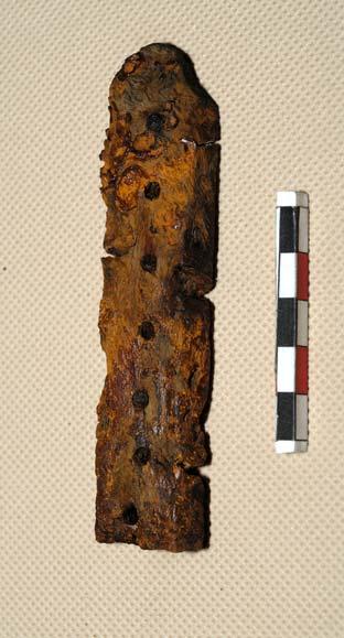
93 Ryc. 1. Kord przed konserwacją, fot. M.R. Rychter Fig. 1. Short sword before conservation, photo: M.R. Rychter Ryc. 4. Okładziny rękojeści kordu, rys. M.R. Rychter Fig. 4. Lining of the short sword hilt, fi g. M.R. Rychter Ryc. 2. Kord z Warty, rys. M.R. Rychter Fig. 2. Short sword from Warta, drawn by M.R. Rychter Ryc. 3. Rękojeść kordu przed konserwacją, fot. M.R. Rychter Fig. 3. Sword hilt before conservation, photo: M.R. Rychter Ryc. 5. Rękojeść kordu po konserwacji, fot. J. Błaszczyk Fig. 5. Short sword hilt after conservation, photo: J. Błaszczyk Ryc. 6. Okładzina rękojeści kordu po konserwacji, fot. J. Błaszczyk Fig. 6. Lining on the short sword hilt after conservation, photo: J. Błaszczyk Wiadomości Konserwatorskie Journal of Heritage Conservation 34/
94 Rękojeść zachowana była bardzo dobrze i praktycznie nie wymagała poważniejszej ingerencji konserwatorskiej. Najprawdopodobniej było to spowodowane zachowaniem się oryginalnych okładzin z materiału organicznego, co w znaczący sposób osłoniło żelazną rękojeść przed korozją (ryc. 4). Grubość okładzin wynosi 7 9 mm. Istotnym problemem konserwatorskim był fakt, że drewniane okładziny rękojeści oryginalnie zespolone były z całością miecza za pomocą, jak się wydawało, wykutych z jednego fragmentu metalu trzpieni. Proces konserwacji wymagał rozdzielenia elementów wykonanych z dwóch grup surowcowych metalu i drewna, ponieważ sposób ich konserwacji i zabezpieczania jest odmienny. Podjęto decyzję o odspojeniu okładzin od rękojeści. Przystąpiono do próby odpiłowania metalowych trzpieni mocujących okładziny. Okazało się jednak, że do zamocowania drewnianych okładzin użyto zwiniętych spiralnie żelaznych blaszek. Z takim sposobem mocowania okładzin autor artykułu, w swojej ponad dwudziestoletniej praktyce konserwatorskiej, spotkał się po raz pierwszy. Wydaje się, że obok estetyki, główną przyczyną wybrania takiego rozwiązania było to, że stale naprężona blaszka spirali dawała mocniejsze zespolenie okładzin z rękojeścią, niż miałoby to miejsce przy klasycznie użytym trzpieniu czy nawet rurkowatym nicie. Po usunięciu bardzo mocno skorodowanych, dających się zatem łatwo usunąć blaszek, udało się oddzielić okładziny od rękojeści miecza. W trakcie konserwacji zabytku stwierdzono, że skorodowana głownia zachowała jednak swój rdzeń metaliczny, a warstwy korozji nie wniknęły zbyt głęboko w strukturę metalu. Okazało się możliwe usunięcie tlenków żelaza bez uszczerbku dla substancji zabytkowej miecza. Dokonano tego stosując kąpiel zabytku w 1-procentowym roztworze kwasu octowego, a następnie mechanicznie usuwając produkty korozji. Czynność tę powtarzano kilkakrotnie, ponieważ zastosowano słaby roztwór kwasu octowego ze względu na agresywność jego działania umożliwiło to kontrolę przebiegu procesu chemicznego, któremu poddano zabytek. Po usunięciu korozji obiekt zanurzono w roztworze kwasu taninowego (taninic acid) o stężeniu 0,001%. Z uwagi na fakt, że Pracownia Konserwacji Zabytków Metalowych Instytutu Archeologii UŁ dysponuje ograniczonym zasobem sprzętowym, opisane czynności wykonano na miejscu, zaś dalszy proces konserwacji przeprowadzono w Pracowni Konserwatorskiej Muzeum Archeologicznego w Krakowie 1. Żelazne elementy miecza pokryto taniną, a następnie poddano działaniu wysokiej temperatury w piecu elektrycznym. Kolejnym etapem konserwacji było zabezpieczenie metalu Paraloidem B44 oraz pokrycie go woskiem mikrokrystalicznym (ryc. 5). Również drewniane okładziny kordu zabezpieczono Paraloidem B44 w komorze próżniowej (ryc. 6). Przekazanie kordu do Pracowni Konserwacji dało również możliwość wykonania specjalistycznych badań wnoszących wiele cennych informacji na temat zastosowanych materiałów oraz technologii produkcji. Najpierw określono rodzaj drewna, z którego wykonano okładziny. Było to bardzo zniszczone i mocno zdegradowane drewno liściaste, rozpierzchłonaczyniowe, przypuszczalnie brzoza (Betula) 2. Drewno brzozy bardzo dobrze nadaje się do wyrobów snycerskich rzeźbiarskich. Dobrze się barwi, poleruje i polituruje, jest łatwo nasycalne roztworami. Ma odporność na działanie kwasów. Problemem, którego nie uda się już chyba wyjaśnić, ze względu na stan zachowania okładzin, jest zagadnienie, czy były one barwione i czy pokryto je warstwą The hilt was very well preserved and practically required no serious conservation treatment. Most probably it was caused by the fact that the original lining from organic material had been preserved, which significantly protected the iron hilt from corrosion (fig. 4). The lining is 7 9 mm thick. A crucial conservation problem was the fact, that wooden insets in the hilt were originally fixed to the rest of the sword by means of tangs, seemingly made from one metal fragment. Conservation process required separating the elements made from two different raw materials metal and wood, since methods of their conservation and protection differ. It was decided to disconnect the lining from the hilt. An attempt was made to saw off metal tangs holding the lining. It turned out, however, that wooden lining was fixed with spiral-shaped iron pieces. The author of the article has encountered such a way of fixing lining for the first time, in his more than twenty years of conservation practice. It seems that, apart from the aesthetic aspect, the main reason behind such a solution was the fact that constantly tautened metal piece in the spiral joined the lining and the hilt better than if a classically applied tang or even a pipe-like rivet had been used. After removing badly corroded and therefore easily removable metal pieces, the lining was separated from the sword hilt. During the conservation of the artefact it turned out that the corroded blade preserved its metallic core, and corrosion layers did not penetrate too deep into the metal structure. Thus it was possible to remove iron oxides without damaging the historic substance of the sword. It was done by bathing the artefact in a 1% solution of acetic acid, and then mechanically removing corrosion products. The process was repeated several times since a weak solution of acetic acid was used because of its aggressive effect, which allowed for controlling the chemical process that the artefact was subjected to. After removing the corrosion, the object was immersed in 0,001% solution of tannic acid. Since the Metal Artefacts Conservation Laboratory at the Institute of Archaeology ŁU has a limited range of equipment at their disposal, the described actions were performed there, while the subsequent conservation process was carried out in the Conservation Laboratory of the Archaeological Museum in Krakow 1. Iron elements of the sword were covered with tannin and then exposed to high temperature in an electric oven. The following stage of conservation was treating the metal with Paraloid B44 and coating it with microcrystalline wax (fig. 5). Wooden lining of the short sword was also treated with Paraloid B44 in a vacuum chamber (fig. 6). Handing the short sword over to the Conservation Lab offered a possibility of carrying out specialist tests which yielded valuable information concerning the used materials and production technologies. Firstly, the kind of wood from which the lining had been made was determined. It was badly damaged and degraded wood of a deciduous tree, presumably birch (Betula) 2. Birchwood is suitable for woodcarving and sculpting. It is easy to colour, polish and veneer, as well as to saturate with solutions, but is resistant to acids. The issue which probably cannot be resolved because of the state of preservation of the lining is whether the wooden insets had been coloured, or covered with a protective layer such as veneer, or whether they had been saturated with a protective substance e.g. plant oil or animal fat. The next question which was examined was the manner of attaching the hilt and the iron pommel. X-ray photos 94 Wiadomości Konserwatorskie Journal of Heritage Conservation 34/2013


 d) Ryc. 10.")


 Fig. 12-15.")
95 a) Ryc. 8. Zdjęcie RTG rękojeści kordu ukazujące jego warstwową budowę Fig. 8. X-ray photo of the short sword hilt revealing its layered structure b) Ryc. 9. Miejsca pobrania prób na badania metalografi czne Fig. 9. Spot from which samples were taken for metallographic tests c) d) Ryc. 10. Preparat ze szlifem metalografi cznym Fig. 10. Preparation with metallographic cut Ryc. 7. Zdjęcie RTG rękojeści kordu z widocznym trzpieniem mocującym Fig. 7. X-ray photo of the short sword hilt with visible fi xing tang Ryc Zdjęcie fragmentu szlifu ukazujące jednorodną strukturę ze śladami kucia (a, b, c, d) Fig Photo of a cut fragment showing homogeneous structure with traces of forging (a, b, c, d) Ryc. 11. Szlif metalografi czny wykonany w poprzek kordu Fig. 11. Metallographic cut made across the short sword Wiadomości Konserwatorskie Journal of Heritage Conservation 34/
96 ochronną, na przykład politurą, bądź też może nasycono je substancją zabezpieczającą, jaką mógł być olej roślinny lub tłuszcz zwierzęcy. Kolejnym zagadnieniem, jakiemu postanowiono się przyjrzeć, był sposób mocowania rękojeści z żelazną głowicą. Wykonano zdjęcia RTG wykazały one, że rękojeść zakończona jest trzpieniem o przekroju prostokątnym, który po przejściu przez głowicę został sklepany na zasadzie nitu o średnicy 8 mm, w zagłębieniu wykonanym w zewnętrznej, górnej powierzchni głowicy (ryc. 7). Zdjęcie RTG ujawniło jeszcze inny, ciekawy, szczegół budowy miecza. Okazało się, że głownia w części stanowiącej rękojeść miecza ma budowę warstwową (ryc. 8). Pozwoliło to wysnuć przypuszczenie, iż miecz został wykonany w technologii skuwania blach lub prętów żelaza, podobnie jak ma to miejsce w produkcji mieczy kultur Dalekiego Wschodu (przykładowo japońska katana). Wykonano również szereg badań metaloznawczych, co wiązało się z pobraniem szeregu próbek (ryc. 9). Najpierw wykonano szlif w poprzek miecza, który miał wyjaśnić, czy faktycznie kord ma budowę warstwową. Ponieważ jest to duża ingerencja w zabytek, ze względu na jego dobro nie można było go wykonać w miejscu, na które wskazywało zdjęcie RTG, czyli w rękojeści miecza, zrobiono go więc na oddzielnym, małym fragmencie głowni (punkt 3 na ryc. 9), w partii końcowej miecza 3. Odcięto wąski kawałek metalu i przygotowano preparat (ryc. 10), zatapiając odcięty fragment w żywicy. Powstały w ten sposób szlif (ryc. 11) poddano badaniom. Wykazały one, że badany fragment metalu wykonano z jednego rdzenia, nie zaś z kilku skutych ze sobą warstw. Wskazują na to zdjęcia wykonane pod mikroskopem (ryc ), na których widoczna jest jednorodna struktura metalu, poprzecinana ciemniejszymi, równoległymi elementami prawdopodobnie żużla, odzwierciedlającymi proces technologiczny, jakim było wykuwanie zabytku. Wykonany szlif dał również możliwość precyzyjnego określenia zawartości pierwiastków składowych występujących w metalu na obszarze udostępnionym metodą badawczą 4. Do tego celu wybrano fragment metalu, w którego strukturze zaobserwowano wyraźną inkluzję z pierwiastków odmiennych od żelaza układającą się zgodnie z technologią kucia miecza, a więc o kształcie bardzo wydłużonej soczewki (ryc. 16). Badana próbka ukazała różną zawartość pierwiastków składowych metalu (ryc. 17). W analizowanym fragmencie metalu wystąpiła słaba zawartość atomów węgla (C) równomiernie rozmieszczonych w polu badawczym. Zagęszczenie atomów węgla widoczne w lewym, górnym rogu pochodzi od żywicy, w której zatopiono preparat 5. Atomy tlenu (O) również rozmieszczone są w miarę równomiernie. Jednakże występuje wyraźna ich koncentracja w miejscu, które określono jako inkluzję w jednorodnej strukturze występującej nieco poniżej środka pola badawczego. Podobna koncentracja występuje również w przypadku atomów aluminium (Al), krzemu (Si), potasu (K) i wapnia (Ca). W miejscu, gdzie występuje koncentracja wymienionych wyżej pierwiastków, brak jest praktycznie atomów żelaza (Fe). Badania ujawniły, że powyższe zanieczyszczenia żelaza układają się w schemat odzwierciedlający technologię wykonania, a więc wykuwania miecza. Opisane zanieczyszczenia nie były widoczne podczas wcześniej wykonanego badania powierzchni zabytku za pomocą elektronowego mikroskopu skaningowego, w dwóch punktach obiektu (punkty 6, 7 na ryc. 9). Badanie metodą mikroskopową wykazało istnienie tylko trzech pierwiastków: żelaza, tlenu i węgla (ryc. 18, 19). revealed that the hilt ended in a tang, rectangular in diameter, which after passing through the pommel was hammered like an 8-mm-diameter rivet, in a groove made in the outer upper surface of the pommel (fig. 7). The X-ray photo showed yet another interesting detail of the sword structure. It turned out that the blade in the section constituting the sword hilt has got a layered structure (fig. 8). That allowed for making an assumption, that the sword was made using the technology of working iron sheets or rods, similarly as in the case of swords produced by the Far East cultures (for instance Japanese katana). Several metalwork tests were also carried out, which was connected with the need to take several samples (fig. 9). Firstly, a cut across the sword was made, which was to clarify whether the short sword really had a layered structure. Since it was a serious interference with the artefact, for its safety it could not be performed in the place indicated by the X-ray photo, i.e. the sword hilt, therefore it was carried out on a separate small fragment of the blade (point 3 in fig. 9) from the end section of the sword 3. A narrow strip of the sword was cut off, from which a preparation was made (fig. 10) by immersing the severed fragment in resin. The cut obtained in this way (fig. 11) was then examined. It showed that the examined metal fragment was made from one core, and not from several layers hammered together. It is shown in the photographs made with a microscope (fig ), in which homogeneous structure of metal is visible, interspersed with darker parallel elements, possibly slag, reflecting the technological process of manufacturing the artefact. The obtained cut made it also possible to precisely determine the content of elements occurring in metal in the area made available by the research method 4. For this purpose a fragment of metal was selected, in whose structure a distinct inclusion of elements other than iron was observed formed in accordance with the technology of sword making, i.e. in the shape of an elongated lens (fig. 16). The examined sample yielded a diverse content of elements in metal (fig. 17). The analysed fragment of metal contained rare atoms of carbon (C) evenly distributed in the examined area. Greater density of carbon particles visible in the top left corner comes from the resin in which the preparation was embedded 5. Atoms of oxygen (O) are also relatively evenly spaced. However, their distinct concentration occurs in the place defined as the inclusion in the homogeneous structure, appearing slightly below the centre of the examined area. A similar concentration occurs also in the case of atoms of aluminum (Al), silicon (Si), potassium (K) and calcium (Ca). In the spot where the above mentioned element are concentrated, there are practically no iron particles (Fe). Research has revealed, that the above contamination of iron show an arrangement reflecting the technology of manufacturing, i.e. forging the sword. The described contamination was not revealed during the previously carried out examination of the artefact surface with a scanning electron microscope, in two points of the object (points 6, 7 in fig. 9). Examination with the microscope showed the existence of only three elements: iron, oxygen and carbon (fig. 18, 19), which proves that it is sometimes necessary to apply such an invasive research method as slicing through an artefact in order to precisely define its structure. The metal fragment was also analysed in infrared to determine the content of carbon in iron 6 6. Four cuts were made (points 4, 5, 6, 7 in fig. 9) from the sword blade, from which six 96 Wiadomości Konserwatorskie Journal of Heritage Conservation 34/2013

 wynik wynosił 0,832% oraz 0,836%. W punkcie 6 (na grzbiecie głowni) 1,03%, natomiast w punkcie research results were obtained.")
97 Dowodzi to, iż niekiedy występuje konieczność sięgania po tak inwazyjną metodę badawczą, jaką jest przecięcie zabytku w poprzek, aby móc precyzyjnie określić jego strukturę. Wykonano również analizę fragmentu metalu w podczerwieni na zawartość węgla w żelazie 6. Wykonano cztery szlify (punkty 4, 5, 6, 7 na ryc. 9) z głowni miecza, z których uzyskano sześć wyników badawczych. W punkcie 4 (w szerszej części głowni) otrzymano 0,656 i 0,656% zawartości węgla. W punkcie 5 (węższa część miecza) wynik wynosił 0,832% oraz 0,836%. W punkcie 6 (na grzbiecie głowni) 1,03%, natomiast w punkcie research results were obtained. In point 4 (in the wider section of the blade) and 0.656% carbon content was obtained. In point 5 (narrower part of the sword) the result was 0.832% and 0.836%. In point 6 (the blade spine) it was 1.03%, while in point 7 (sword edge) 0.98%. Analysing the measurement results it can be observed that the carbon content in iron varies, which implies that the examined fragment must have been hardened by carburising its surface. In case of introducing carbon into steel directly in the metallurgic process, the carbon content in the whole cross-section would have been similar. Ryc. 16. Fragment szlifu wybrany na badania składu pierwiastków Fig. 16. Selected fragment of the cut for tests of element content Ryc. 19. Skład pierwiastkowy określony bez szlifu dół kordu Fig. 19. Element content made without the cut bottom of short sword Ryc. 17. Skład pierwiastkowy badanego pola szlifu Fig. 17. Element content of the examined cut area Ryc. 18. Skład pierwiastkowy określony bez szlifu góra kordu Fig. 18. Element content made without the cut top of short sword Ryc. 20. skład pierwiastkowy prób pobranych z elementów ozdobnych: krzyża i osłony na okładziny drewniane Fig. 20. Element content of samples taken from decorative elements: cross and guard for wooden lining Wiadomości Konserwatorskie Journal of Heritage Conservation 34/
98 7 (ostrze miecza) 0,98%. Analizując wyniki pomiaru można stwierdzić, że występuje zróżnicowanie zawartości węgla w żelazie, co sugeruje, że najprawdopodobniej badany fragment został utwardzony poprzez nawęglenie powierzchni. W przypadku wprowadzenia węgla do stali bezpośrednio w procesie metalurgicznym, stężenie węgla w całym przekroju byłoby podobne. Nie należy zapominać o części miecza wykonanej z żelaza, która nie została poddana specjalistycznym badaniom (np. przez wykonanie szlifu) ze względu na dobro zabytku, który zostałby w ten sposób znacznie uszkodzony. Mowa tutaj o głowicy rękojeści miecza z inkrustacją ze stopu miedzi w kształcie krzyża. Sposób wykonania głowicy nie jest znany, zapewne także została wykuta, jednak nie był to tak intensywny proces, jak przy wykonywaniu głowni. Po procesie kucia głownia uzyskała strukturę włóknistą, natomiast wspomniana głowica ma strukturę jednolitą i podczas procesu korozji wytworzyły się na niej mikroskopijne koliste wżery. Zbadano również elementy ozdobne miecza wykonane ze stopów miedzi pod kątem składu pierwiastkowego. Pobrano małe próbki metalu z krzyża (punkt 1 na ryc. 9) a także z dekoracyjnego elementu przymocowanego do dolnej części głowicy, na granicy z drewnianymi okładzinami miecza (punkt 2 na ryc. 9). Okazało się, że metalem użytym do wyrobu tych detali był mosiądz (ryc. 20). W przypadku krzyża mosiądz był zanieczyszczony ołowiem. Natomiast osłonę wykonano z mosiądzu bez żadnej domieszki. Być może powodem było to, że oba fragmenty nie zostały wykonane z metalu pochodzącego z jednego tygla. Nie mamy jednak pewności co do tego, ponieważ metoda badawcza zastosowana do analizy jest precyzyjna jedynie w odniesieniu do określonego obszaru próby. Nie daje wglądu w skład pierwiastkowy całości, który można określić np. za pomocą analizy rentgenowskiej. Być może tylko w badanym fragmencie mogło wystąpić zanieczyszczenie ołowiem, co nie jest wykluczone, ponieważ ołów, jak i wiele innych pierwiastków, zwłaszcza srebro, jest naturalną częścią składową rud miedzi. One should not forget the part of the sword made from iron, which was not subjected to specialist examination (e.g. by making a cut) for the safety of the artefact which would have been seriously damaged. we mean here the pommel of the sword hilt with its incrustation from a copper alloy in the shape of a cross. The manner of manufacturing the pommel is not known, it might have been forged, though it was not as intensive a process as in the case of manufacturing the blade. After the forging process the blade obtained a fibrous structure, while the already mentioned pommel has a homogeneous structure and microscopic circular pits appeared in it as a result of the corrosive process. Decorative elements of the sword made from copper alloys were also examined concerning their element content. Small samples were taken from the metal of the cross (point 1 in fig. 9), as well as the decorative element fixed to the lower section of the pommel, where it joined the wooden lining of the sword (point 2 in fig. 9). It appeared that brass was the metal used for manufacturing those details (fig. 20). In the case of the cross, brass was contaminated with lead, while the guard was made from brass without any additions. It might have been caused by the fact that both fragments were not made from metal from one melting pot. However, we cannot be certain of it, since the research method applied for the analysis is precise only for a concrete given examined area. It offers no insight into the element content of the whole, which could be determined by e.g. X-ray analysis. The lead contamination might have occurred only within the examined fragment, which cannot be ruled out, since lead and many other elements, especially silver, are natural ingredients in copper ore Serdecznie dziękuję Dyrekcji Muzeum Archeologicznego w Krakowie, a w szczególności szefowi konserwatorów Panu Andrzejowi Dydze za pomoc w konserwacji miecza. Gatunek drewna określiła Pani Maria Michniewicz, za co jej serdecznie dziękuję. Badania szlifu opracował prof. dr hab. Leszek Klimek z Instytutu Inżynierii Materiałowej Politechniki Łódzkiej. Wszystkie analizy, w tym również badanie składu pierwiastkowego, wykonano elektronowym mikroskopem skaningowym S 3000 N 5 6 firmy Hitachi będącym na wyposażeniu Instytutu Inżynierii Materiałowej Wydziału Mechanicznego Politechniki Łódzkiej. Lewy, górny róg widocznego pola badawczego jest fragmentem żywicy, w której zatopiono preparat, co wyklucza ten obszar z analiz podstawowych dla preparatu. Badanie wykonał dr inż. Konrad Dybowski z Zakładu Badań Materiałów Instytutu Inżynierii Materiałowej Politechniki Łódzkiej. Streszczenie Artykuł opisuje konserwację i specjalistyczne badania metalograficzne XV-wiecznego kordu przypadkowo odkrytego w mieście Warta w woj. łódzkim. O wyjątkowości znaleziska świadczy fakt zachowania się drewnianych okładzin rękojeści. Unikalny charakter ma również dekoracja głowicy miecza w postaci asymetrycznego krzyża z mosiądzu. Opisano proces konserwacji elementów drewnianych i metalowych, a także badania składu pierwiastkowego oraz szlify metaloznawcze. Abstract The article describes the conservation and specialist metallographic examination of the 15 th -century short sword accidentally discovered in the town of Warta, Łódz Voivodeship. The unique character of the find is reflected by the fact that the wooden insets on the hilt have been preserved. Decoration of the sword pommel in the shape of an asymmetrical cross made of brass is also unique. The process of conservation of wooden and metal elements has been described, as well as the examination of the element content and metalwork cuts. 98 Wiadomości Konserwatorskie Journal of Heritage Conservation 34/2013
99 INFORMACJE INFORMATION Krzysztof Stępiński Międzynarodowy Dzień Ochrony Zabytków kwietnia 2013, Łowicz International Monument Protection Day April 2013, Łowicz W bieżącym roku mija dokładnie trzydzieści lat od ustanowienia Międzynarodowego Dnia Ochrony Zabytków. W 1983 r. Międzynarodowa Rada Ochrony Zabytków ICOMOS wybrała 18 kwietnia jako datę tego święta, które w miarę upływu czasu stało się imprezą o światowym znaczeniu, obchodzoną w bardzo wielu krajach. W Polsce przyjęła się tradycja organizowania centralnych obchodów Międzynarodowego Dnia Ochrony Zabytków w miastach uznanych za Pomniki Historii dzięki ich cennym i zadbanym zabytkom oraz ważnym dla polskich dziejów miejscom. W 2011 r. gala Międzynarodowego Dnia Ochrony Zabytków odbyła się w Gnieźnie, a w 2012 w Stargardzie Szczecińskim. Miejscem tegorocznych obchodów był Łowicz. Współorganizatorami imprezy były: Urząd Miejski w Łowiczu, Starostwo Powiatowe w Łowiczu i Urząd Marszałkowski w Łodzi wespół z Narodowym Instytutem Dziedzictwa. Honorowy patronat nad obchodzami objęli: Generalny Konserwator Zabytków, Sekretarz Stanu w Ministerstwie Kultury i Dziedzictwa Narodowego Piotr Żuchowski, Marszałek Województwa Łódzkiego Witold Stępień i Biskup Łowicki Andrzej Franciszek Dziuba. Położony na granicy Mazowsza i Ziemi Łódzkiej Łowicz już w XII wieku należał do dóbr arcybiskupa gnieźnieńskiego, a pod koniec wieku XIII wzmiankuje się o posiadaniu przez Łowicz praw miejskich. Do najcenniejszych sakralnych zabytków w mieście należy dawna kolegiata, obecnie Bazylika Katedralna pw. Wniebowzięcia Najświętszej Marii Panny i św. Mikołaja w renesansowo-barokowym stylu, z imponującą fasadą przebudowaną w XVII w. według projektu Tomasza z Poncino. Spośród 6 kaplic trójnawowej Bazyliki wyróżnia się szczególnie XVI-wieczna kaplica pw. św. Wiktorii, patronki Łowicza. W mieście istnieje także wiele innych pięknych kościołów i klasztorów, powstałych głównie w XVII i XVIII wieku i typowych dla ówczesnego polskiego baroku. Charakterystyczne dla Łowicza są też uroczyste procesje odbywane w dni wielkich świąt katolickich, takich jak Zielone Świątki czy Boże Ciało. Okoliczna ludność, znana jako Księżacy łowiccy, przybywa na obchody tych świąt w wielobarwnych strojach ludowych, tzw. pasiakach. W istocie, ziemie wokół Łowicza od dawna zwane były Księstwem Łowickim. Pierwotnie było ono częścią dóbr arcybiskupa gnieźnieńskiego. Przejęte po III rozbiorze przez rząd pruski, w 1807 przekazane zostało przez Napoleona jednemu z jego marszałków. W 1820 r. car Aleksander I podarował Księstwo Łowickie swemu bratu, namiestnikowi Królestwa Polskiego wielkiemu księciu Konstantemu i jego żonie Joannie Grudzińskiej. W latach 30. XIX w., po klęsce powstania listopadowego, ziemie Księstwa przejął car Mikołaj I. Wśród świeckich zabytków Łowicza wymienić należy Stary Rynek z renesansowo-barokową zabudową i ukończonym w 1828 roku Ratuszem Miejskim przykładem pięknej budowli w stylu klasycystycznym. Obok Ratusza stoi kamienica zwana Napoleońską, w której cesarz Francuzów zatrzymał się na krótko w grudniu1806 r. W Łowiczu znajduje się także bardzo ciekawy architektonicznie, trójkątny Nowy Rynek z kamienicami wznoszonymi i przebudowywanymi w XVII, XVIII i XIX w. oraz dawnym renesansowym ratuszem. Obchody Międzynarodowego Dnia Ochrony Zabytków 18 kwietnia 2013 roku odbywały się w miejscu, w którym łączy się sakralna i świecka tradycja zabytkowego Łowicza mianowicie w kaplicy św. Karola Boromeusza znajdującej się w Muzeum Łowickim. Wynika to z faktu, iż Muzeum mieści się w barokowym gmachu dawnego Seminarium Księży Misjonarzy, ufundowanym przez prymasa Michała Stefana Radziejowskiego i wzniesionym w l przez Tylmana z Gameren. Malowidła sklepienia kaplicy należą do najpiękniejszych osiągnięć polskiego i europejskiego baroku. Gości obchodów Międzynarodowego Dnia Ochrony Zabytków powitał Starosta Łowicki Krzysztof Figat. Następnie wystąpienia powitalne wygłosili: Marszałek Województwa Łódzkiego Witold Stępień, Generalny Konserwator Zabytków Piotr Żuchowski, Dyrektor Narodowego Instytutu Dziedzictwa Paulina Florjanowicz i Burmistrz Miasta Łowicza Krzysztof Jan Kaliński. Witając gości i życząc im udanego pobytu, mówcy przywoływali m.in. historię Ziemi Łowickiej i jej zabytków oraz ogólniejsze problemy związane z ochroną i konserwacją zabytków w dzisiejszych czasach, charakteryzujących się trudnościami gospodarczymi, ale także nowymi możliwościami dzięki stale udoskonalanym technikom i materiałom konserwatorskim oraz dzięki wykorzystaniu funduszy europejskich. Edukacji, promocji i ochronie dziedzictwa kulturowego najlepiej służy coroczny Konkurs Generalnego Konserwatora Zabytków Zabytek Zadbany. Do konkursu w 2013 r. zgłoszono 65 wniosków ze wszystkich województw. Regulamin dopuszczał kandydowanie w jednej z 5 kategorii. Wiadomości Konserwatorskie Journal of Heritage Conservation 34/
100 Po krótkim koncercie wykonanym przez zespół Ars Nova wraz z chórem Cantilena klasztoru Sióstr Urszulanek SJK i złożonym z utworów Mikołaja Zieleńskiego i Cypriana Bazylika, nastąpiło ogłoszenie wyników konkursu Zabytek Zadbany. Nagrody laureatom wręczali: Generalny Konserwator Zabytków, Wiceminister Piotr Żuchowski i Dyrektor Narodowego Instytutu Dziedzictwa Paulina Florjanowicz. W kategorii Utrwalenie wartości zabytkowej pojedynczego obiektu nagrodzono dwór w zespole dworsko-parkowym w Łękach Górnych w województwie podkarpackim, wzniesiony w latach w stylu renesansowo-manierystycznym i rozbudowywany w wieku XIX oraz w latach 20. XX w. Właścicielami zabytku są Joanna i Dariusz Kolbuszowie. Przyznając tę nagrodę, jury doceniło przede wszystkim kompleksowy charakter prac konserwatorskich przeprowadzonych po uprzednich starannych badaniach rozpoznawczych obiektu. W trakcie konserwacji udało się zachować substancję architektoniczną i cenny historyczny wystrój wnętrza dworu. Dokonano również udanej rewaloryzacji parku wokół dworu i reliktów dawnych fortyfikacji. Wyróżnienia w kategorii Utrwalenie wartości zabytkowej pojedynczego obiektu otrzymały nastepujące zabytki i ich właściciele: Kamienica Pod Złotym Orłem, obecnie Muzeum Farmacji we Wrocławiu, województwo dolnośląskie (właściciel: Uniwersytet Medyczny im. Piastów Śląskich we Wrocławiu), Wieża Bramy Wrocławskiej w Nysie, woj. opolskie (właściciel: Miasto i Gmina Nysa), Budynek dawnej resursy w Żyrardowie, woj. mazowieckie (właściciel: Miasto Żyrardów). W kategorii Rewaloryzacja przestrzeni kulturowej i krajobrazu laureatem konkursu został Zespół pałacowo- -parkowy z basztą obronną w Żmigrodzie, woj. dolnośląskie. Właścicielem obiektu jest Miasto i Gmina Żmigród. Najstarszą część zespołu renesansową wieżę z XVI wieku zwaną Kasztelańską wyremontowano i zadaptowano na punkt informacji turystycznej oraz potrzeby Urzędu Miasta. Barokowy Pałac Hatzfeldów, zniszczony pod koniec wojny w 1945 roku, zabezpieczono i zakonserwowano w formie trwałej ruiny. Trzecią część prac stanowiła rewaloryzacja parku z 2. poł. XIX i początków XX wieku. W uzasadnieniu nagrody podkreślono wieloapsektowy charakter rewaloryzacji oraz udane rozwiązanie konstrukcyjnych i estetycznych problemów wynikajacych z różnorodności poszczególnych elementów zabytkowego zespołu. Wyróżnienia w tej kategorii otrzymały: Domy tkaczy w Parku Kulturowym Miasto Tkaczy w Zgierzu w woj. łódzkim (właściciel: Miasto Zgierz), Zespół parkowy dawnego klasztoru cysterek w Owińskach, woj. wielkopolskie (właściciel: Starostwo Powiatowe w Poznaniu), Zespół Żuławskiego Parku Historycznego w Nowym Dworze Gdańskim w woj. pomorskim; zarządcą zabytku jest Stowarzyszenie Miłośników Nowego Dworu Gdańskiego Klub Nowodworski. W kategorii Adaptacja obiektów zabytkowych nagrodzono remont i konserwację wraz z adaptacją dawnej chasydzkiej Synagogi, wzniesionej w l. 60. XIX wieku, dla której przeznaczono nową funkcję Ośrodka Spotkania Kultur. Na remont Synagogi złożyły się zarówno ratownicze interwencje konstrukcyjne i prace konserwatorsko-adaptacyjne, jak też przeprowadzona na bardzo wysokim poziomie konserwacja dekoracji sztukatorskich i malarskich. Autorom prac zależało bowiem, by dostosowanie obiektu do nowej, istotnej społecznie funkcji dokonało się z pełnym poszanowaniem autentyczności i integralności substancji zabytkowej i otoczenia budowli. Wyróżnienia w kategorii Adaptacja obiektów zabytkowych otrzymały: Budynek Łaźni miejskiej w Gdańsku, woj. pomorskie, będącej obecnie w posiadaniu Centrum Sztuki Współczesnej Łaźnia i stanowiacej gdańskie Centrum Edukacji Artystycznej Łaźnia 2, Donżon Twierdzy Srebrna Góra w woj. dolnośląskim, po konserwacji przeznaczony do funkcji turystycznej i muzealno-wystawienniczej (właścicielem zabytku jest Forteczny Park Kulturowy Spółka z o.o.), Folwarczna wieża ciśnień w Skorogoszczy w woj. opolskim, przekształcona obecnie w wieżę widokową i izbę regionalną (właściciel: Dariusz Zięba). W kategorii specjalnej Architektura i konstrukcje drewniane nagrodę otrzymał Kościól filialny św. Anny w Brzezinach w woj. łódzkim należący do Parafii Rzymskokatolickiej Podwyższenia Świętego Krzyża w Brzezinach. Drewniany kościół powstał w 1719 roku z zachowaniem starszej murowanej kaplicy z 1616 r. Zagrożony zniszczeniem zabytek ratowano od 2004 r., przeprowadzając m.in. szeroki program badawczy ze szczegółową inwentaryzacją obiektu, badaniami architektonicznymi i badaniami na obecność warstw malarskich. Pozwoliło to zachować w wysokim stopniu autentyzm unikalnego drewnianego zabytku. Wyróżnienie w kategorii zabytków drewnianych otrzymał Dom podmiejski z kuźnią w Gdańsku, woj. pomorskie, zarządzany przez Gdański Zarząd Nieruchomości Komunalnych Samorządowy Zakład Budżetowy. W kategorii specjalnej Architektura przemysłowa i dziedzictwo techniki nagrodzono Zespół Starej Przędzalni w Żyrardowie, woj. mazowieckie. Właścicielem zabytku jest Spółka z o.o. Stara Przędzalnia. Zespół składa się z trzech przylegających do siebie budynków najstarszy powstawał od 1822 r., czyli w początkach rozwoju przemysłu przędzalniczego w Żyrardowie. Budynki Starej Przędzalni stanowiły pierwsze centrum osady fabrycznej i są najlepszym świadectwem historii Żyrardowa oraz poprzemysłowego charakteru architektury miasta. Kompleksowe prace konserwatorskie obejmowały remont i renowację zagrożonych hal, konserwację elewacji zewnętrznych i elementów wnętrz oraz rewitalizację otoczenia budynków, stanowiących dominantę na osi placu targowego obecnie placu Jana Pawła II. Wyróżnienia w tej kategorii otrzymały: Most na Bystrzycy w Lublinie (właściciel: Miasto Lublin), Wieża Wodna we Fromborku w woj. warmińsko-mazurskim, której właścicielami są Dobromira i Zygmunt Czarneccy, Kordegarda i bydynek biurowy w zespole dawnej Warszawskiej Wytwórni Wódek Koneser na warszawskiej Pradze, woj. mazowieckie (właściciel: BBI Development NFI SA). Celem właściwie każdej konserwacji obiektu nagrodzonego czy wyróżnionego w konkursie Zabytek Zadbany było uratowanie niszczejącego zabytku i włączenie go we współczesną rzeczywistość przy jednoczesnym zachowaniu oryginalnej substancji zabytkowej w możliwie maksymalnym stopniu. Takie jest najważniejsze przesłanie konkursu. Ma on zachęcać prywatnych i instytucjonalnych właścicieli, opieku- 100 Wiadomości Konserwatorskie Journal of Heritage Conservation 34/2013
101 nów i zarządców zabytków do ochrony i konserwacji, a także do właściwego zagospodarowania i użytkowania obiektów wpisanych do rejestru zabytków. Uroczysta kolacja w Dworku Biała Dama w Nieborowie zakończyła pierwszy dzień obchodów Międzynarodowego Dnia Ochrony Zabytków. Następnego dnia, 19 kwietnia 2013 r. o godzinie dziewiątej rano w Bazylice Katedralnej pod wezwaniem Wniebowzięcia Najświętszej Marii Panny w Łowiczu odprawiona została msza święta w intencji konserwatorów polskich i śp.tomasza Merty, Generalnego Konserwatora Zabytków, w 3. rocznicę Jego śmierci w katastrofie smoleńskiej. Przed południem uczestnicy obchodów Międzynarodowego Dnia Ochrony Zabytków mogli wziąć udział w objeździe studialnym zorganizowanym przez Urząd Miasta Łowicz. Goście mieli do wyboru trzy trasy: Łowicz Maurzyce, Łowicz Arkadia Nieborów, Łowicz Sromów. Spośród tych miejscowości najlepiej znany jest oczywiście Nieborów ze wzniesionym tam pod koniec XVII w. wspaniałym barokowym pałacem Radziwiłłów (obecnie oddział Muzeum Narodowego i Dom Pracy Twórczej). Pobliska Arkadia to słynny park romantyczno-sentymentalny założony pod koniec XVIII wieku przez Helenę z Przeździeckich Radziwiłłową, z pięknymi kameralnymi budowlami, dla których inspirację stanowiły przede wszystkim wzory antyczne, a także styl gotycki. W położonym o kilka kilometrów na północny wschód od Łowicza Sromowie istnieje Muzeum Ludowe Rodziny Brzozowskich. Imponujące są zbiory ruchomych rzeźb ludowych (figury używane podczas procesji, szopki bożonarodzeniowe czy łowickie wesele), a także łowickich strojów, wycinanek, wyposażenia wnętrz. Powozownia mieści kolekcję 35 pojazdów konnych. W leżących na zachód od Łowicza Maurzycach mieści się Skansen Wsi Łowickiej, gdzie zgromadzono ok. 40 różnych budowli, odtwarzając m.in. typ tzw. starej wsi owalnicy i tzw. nowej wsi ulicówki. Obiad w restauracji Finezja Smaków przy łowickim Starym Rynku, dokąd organizatorzy zaprosili gości, zakończył obchody Międzynarodowego Dnia Ochrony Zabytków 2013 roku. Obchody te miały nieco inny charakter niż w poprzednich latach, gdyż część uroczystości przygotowywana przez Stowarzyszenie Konserwatorów Zabytków wraz z wręczeniem nagród SKZ odbędzie się w tym roku oddzielnie: w trakcie wrześniowych Europejskich Dni Dziedzictwa w Krakowie. Sprawozdanie opracowano na podstawie materiałów NID-u oraz Urzędu Miasta Łowicza. Streszczenie Gospodarzem polskich obchodów Międzynarodowego Dnia Ochrony Zabytków w dniu 18 kwietnia 2013 roku był Łowicz powiatowe miasto położone niemal w samym środku Polski, w połowie drogi między stolicą kraju Warszawą a innym wielkim miastem Łodzią. Historia Łowicza sięga XII-XIII wieku. Nieduże miasto pełne jest zabytkowych budowli: barokowych kościołów z XVII XVIII wieku czy kamienic, dworków i innych miejskich zabytków powstałych w epoce renesansu, baroku i XIX- -wiecznego klasycyzmu. Organizatorami uroczystej gali Międzynarodowego Dnia Ochrony Zabytków 2013 były władze miejskie Łowicza, władze województwa łódzkiego oraz mający siedzibę w Warszawie Narodowy Instytut Dziedzictwa centralna instytucja powołana do ochrony, katalogowania i dokumentowania polskich zabytków. Uroczystości odbywały się w barokowej kaplicy św. Karola Boromeusza w Muzeum w Łowiczu, gdzie pierwotnie mieściło się kościelne seminarium. Najważniejszym punktem obchodów było wręczenie nagród w konkursie Generalnego Konserwatora Zabytków. Celem konkursu jest zainspirowanie właścicieli, zarządców i opiekunów zabytków do ich ratowania, konserwacji, trwałej ochrony i należytego użytkowania. Nagroda przyznawana jest w 5 kategoriach. W 2013 r. nagrodzono dwór z końca XVI w. w południowo-wschodniej Polsce, zespół pałacowo-parkowy na Dolnym Śląsku, XIX-wieczną Synagogę na południu kraju zaadaptowaną na Ośrodek Spotkania Kultur, unikalny kościół drewniany z XVIII w. położony koło Łodzi i zrewitalizowaną Abstract The host of Polish celebrations of the International Monument Protection Day which took place on 18 April 2013, was Łowicz a county town located almost in the very centre of Poland, half way between the capital, Warsaw, and another large city Łódź. The history of Łowicz goes back to the 12 th -13 th century. The town in full of historic buildings: Baroque churches from the 17 th -18 th century or tenement houses, mansions and other urban monuments erected during the Renaissance, Baroque or the 19 th -century classicist period. The gala ceremony of the International Monument Protection Day 2013 was organised by the local authorities of Łowicz, Łodz Voivodeship authorities and, located in Warsaw, National Heritage Institute a central institution appointed to protect, catalogue and document Polish monuments. The venue was the Baroque chapel of St. Charles Borromeo in the Museum in Łowicz, where a church seminary had originally been housed. The highlight of the celebrations was giving awards in the competition of the General Monument Conservator. The aim of the competition is inspiring owners, managers and guardians of historic objects to save, conserve, protect and properly use them. There are five categories of the award. In 2013, the awards went to: a manor from the end of the 16 th c. in south eastern Poland, a palace and park complex in Lower Silesia, a 19 th -century Synagogue in the south of our country adapted for a Centre for Cultural Encounters, a unique wooden church from the 18 th c. located in the vicinity of Łódź, and a revitalised old textile factory in Żyrardow an industrial town near Warsaw. Wiadomości Konserwatorskie Journal of Heritage Conservation 34/
102 dawną fabrykę włókienniczą w Żyrardowie przemysłowym mieście niedaleko Warszawy. Obchody MDOZ były także okazją do licznych nieformalnych spotkań środowiska osób zajmujacych się profesjonalnie lub z własnej pasji ochroną zabytków, a także sposobnością do wspólnych uroczystych obiadów i kolacji. 19 kwietnia rano odprawiona została msza w intencji konserwatorów polskich. Następnie goście imprezy mogli zwiedzać leżące wokół Łowicza atrakcyjne miejsca: Muzeum Ludowe w Sromowie, Skansen Wsi Łowickiej w Maurzycach i barokowy pałac w Nieborowie z pobliskim pięknym romantyczno-sentymentalnym parkiem w stylu angielskim, nazwanym Arkadią. Celebrations of the IMPD were also an opportunity for numerous informal meetings of people who, either by profession or by passion, were keen on preserving historic objects, as well as a chance for formal lunches and dinners. In the morning of 19 April, a Mass for Polish conservators was celebrated. Then the guests could visit attractive sites located in the proximity of Łowicz: a Folk Museum in Sromów, an Open-air Museum of Łowicz Countryside in Maurzyce and a Baroque palace in Nieborów with the nearby beautiful romantic sentimental English style park, known as Arcadia. 102 Wiadomości Konserwatorskie Journal of Heritage Conservation 34/2013
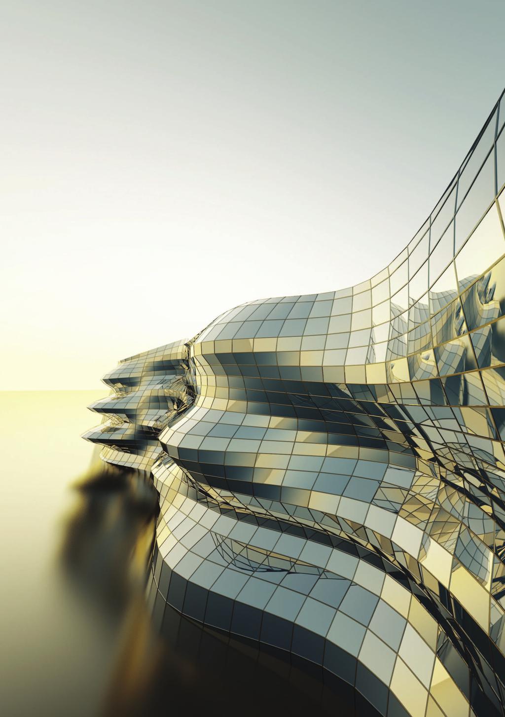


103 NOWOŚĆ

104
Lecture 18 Review for Exam 1
 Spring, 2019 ME 323 Mechanics of Materials Lecture 18 Review for Exam 1 Reading assignment: HW1-HW5 News: Ready for the exam? Instructor: Prof. Marcial Gonzalez Announcements Exam 1 - Wednesday February
Rada Naukowa Scientific Board
 34 / 2013 Radaktor Naczelny Editor In Chief Prof. dr hab. Kazimierz Kuśnierz Redaktorzy Tematyczni Topical Editors Dr Łukasz Bednarz (konstrukcje murowane / masonry structures), Politechnika Wrocławska
Zakopane, plan miasta: Skala ok. 1: = City map (Polish Edition)
") Zakopane, plan miasta: Skala ok. 1:15 000 = City map (Polish Edition) Click here if your download doesn"t start automatically Zakopane, plan miasta: Skala ok. 1:15 000 = City map (Polish Edition) Zakopane,
Zakopane, plan miasta: Skala ok. 1:15 000 = City map (Polish Edition) Click here if your download doesn"t start automatically Zakopane, plan miasta: Skala ok. 1:15 000 = City map (Polish Edition) Zakopane,
SSW1.1, HFW Fry #20, Zeno #25 Benchmark: Qtr.1. Fry #65, Zeno #67. like
 SSW1.1, HFW Fry #20, Zeno #25 Benchmark: Qtr.1 I SSW1.1, HFW Fry #65, Zeno #67 Benchmark: Qtr.1 like SSW1.2, HFW Fry #47, Zeno #59 Benchmark: Qtr.1 do SSW1.2, HFW Fry #5, Zeno #4 Benchmark: Qtr.1 to SSW1.2,
Stargard Szczecinski i okolice (Polish Edition)
") Stargard Szczecinski i okolice (Polish Edition) Janusz Leszek Jurkiewicz Click here if your download doesn"t start automatically Stargard Szczecinski i okolice (Polish Edition) Janusz Leszek Jurkiewicz
Stargard Szczecinski i okolice (Polish Edition) Janusz Leszek Jurkiewicz Click here if your download doesn"t start automatically Stargard Szczecinski i okolice (Polish Edition) Janusz Leszek Jurkiewicz
Wojewodztwo Koszalinskie: Obiekty i walory krajoznawcze (Inwentaryzacja krajoznawcza Polski) (Polish Edition)
 (Polish Edition)") Wojewodztwo Koszalinskie: Obiekty i walory krajoznawcze (Inwentaryzacja krajoznawcza Polski) (Polish Edition) Robert Respondowski Click here if your download doesn"t start automatically Wojewodztwo Koszalinskie:
Wojewodztwo Koszalinskie: Obiekty i walory krajoznawcze (Inwentaryzacja krajoznawcza Polski) (Polish Edition) Robert Respondowski Click here if your download doesn"t start automatically Wojewodztwo Koszalinskie:
Proposal of thesis topic for mgr in. (MSE) programme in Telecommunications and Computer Science
 programme in Telecommunications and Computer Science") Proposal of thesis topic for mgr in (MSE) programme 1 Topic: Monte Carlo Method used for a prognosis of a selected technological process 2 Supervisor: Dr in Małgorzata Langer 3 Auxiliary supervisor: 4
Proposal of thesis topic for mgr in (MSE) programme 1 Topic: Monte Carlo Method used for a prognosis of a selected technological process 2 Supervisor: Dr in Małgorzata Langer 3 Auxiliary supervisor: 4
Tychy, plan miasta: Skala 1: (Polish Edition)
") Tychy, plan miasta: Skala 1:20 000 (Polish Edition) Poland) Przedsiebiorstwo Geodezyjno-Kartograficzne (Katowice Click here if your download doesn"t start automatically Tychy, plan miasta: Skala 1:20 000
Tychy, plan miasta: Skala 1:20 000 (Polish Edition) Poland) Przedsiebiorstwo Geodezyjno-Kartograficzne (Katowice Click here if your download doesn"t start automatically Tychy, plan miasta: Skala 1:20 000
EXAMPLES OF CABRI GEOMETRE II APPLICATION IN GEOMETRIC SCIENTIFIC RESEARCH
 Anna BŁACH Centre of Geometry and Engineering Graphics Silesian University of Technology in Gliwice EXAMPLES OF CABRI GEOMETRE II APPLICATION IN GEOMETRIC SCIENTIFIC RESEARCH Introduction Computer techniques
Karpacz, plan miasta 1:10 000: Panorama Karkonoszy, mapa szlakow turystycznych (Polish Edition)
") Karpacz, plan miasta 1:10 000: Panorama Karkonoszy, mapa szlakow turystycznych (Polish Edition) J Krupski Click here if your download doesn"t start automatically Karpacz, plan miasta 1:10 000: Panorama
Karpacz, plan miasta 1:10 000: Panorama Karkonoszy, mapa szlakow turystycznych (Polish Edition) J Krupski Click here if your download doesn"t start automatically Karpacz, plan miasta 1:10 000: Panorama
ARNOLD. EDUKACJA KULTURYSTY (POLSKA WERSJA JEZYKOWA) BY DOUGLAS KENT HALL
 BY DOUGLAS KENT HALL") Read Online and Download Ebook ARNOLD. EDUKACJA KULTURYSTY (POLSKA WERSJA JEZYKOWA) BY DOUGLAS KENT HALL DOWNLOAD EBOOK : ARNOLD. EDUKACJA KULTURYSTY (POLSKA WERSJA Click link bellow and free register
Read Online and Download Ebook ARNOLD. EDUKACJA KULTURYSTY (POLSKA WERSJA JEZYKOWA) BY DOUGLAS KENT HALL DOWNLOAD EBOOK : ARNOLD. EDUKACJA KULTURYSTY (POLSKA WERSJA Click link bellow and free register
MaPlan Sp. z O.O. Click here if your download doesn"t start automatically
 Mierzeja Wislana, mapa turystyczna 1:50 000: Mikoszewo, Jantar, Stegna, Sztutowo, Katy Rybackie, Przebrno, Krynica Morska, Piaski, Frombork =... = Carte touristique (Polish Edition) MaPlan Sp. z O.O Click
Helena Boguta, klasa 8W, rok szkolny 2018/2019
 Poniższy zbiór zadań został wykonany w ramach projektu Mazowiecki program stypendialny dla uczniów szczególnie uzdolnionych - najlepsza inwestycja w człowieka w roku szkolnym 2018/2019. Składają się na
 www.irs.gov/form990. If "Yes," complete Schedule A Schedule B, Schedule of Contributors If "Yes," complete Schedule C, Part I If "Yes," complete Schedule C, Part II If "Yes," complete Schedule C, Part
Katowice, plan miasta: Skala 1: = City map = Stadtplan (Polish Edition)
") Katowice, plan miasta: Skala 1:20 000 = City map = Stadtplan (Polish Edition) Polskie Przedsiebiorstwo Wydawnictw Kartograficznych im. Eugeniusza Romera Click here if your download doesn"t start automatically
Katowice, plan miasta: Skala 1:20 000 = City map = Stadtplan (Polish Edition) Polskie Przedsiebiorstwo Wydawnictw Kartograficznych im. Eugeniusza Romera Click here if your download doesn"t start automatically
 www.irs.gov/form990. If "Yes," complete Schedule A Schedule B, Schedule of Contributors If "Yes," complete Schedule C, Part I If "Yes," complete Schedule C, Part II If "Yes," complete Schedule C, Part
Miedzy legenda a historia: Szlakiem piastowskim z Poznania do Gniezna (Biblioteka Kroniki Wielkopolski) (Polish Edition)
 (Polish Edition)") Miedzy legenda a historia: Szlakiem piastowskim z Poznania do Gniezna (Biblioteka Kroniki Wielkopolski) (Polish Edition) Piotr Maluskiewicz Click here if your download doesn"t start automatically Miedzy
Miedzy legenda a historia: Szlakiem piastowskim z Poznania do Gniezna (Biblioteka Kroniki Wielkopolski) (Polish Edition) Piotr Maluskiewicz Click here if your download doesn"t start automatically Miedzy
Convolution semigroups with linear Jacobi parameters
 Convolution semigroups with linear Jacobi parameters Michael Anshelevich; Wojciech Młotkowski Texas A&M University; University of Wrocław February 14, 2011 Jacobi parameters. µ = measure with finite moments,
Installation of EuroCert software for qualified electronic signature
 Installation of EuroCert software for qualified electronic signature for Microsoft Windows systems Warsaw 28.08.2019 Content 1. Downloading and running the software for the e-signature... 3 a) Installer
Machine Learning for Data Science (CS4786) Lecture 11. Spectral Embedding + Clustering
 Lecture 11. Spectral Embedding + Clustering") Machine Learning for Data Science (CS4786) Lecture 11 Spectral Embedding + Clustering MOTIVATING EXAMPLE What can you say from this network? MOTIVATING EXAMPLE How about now? THOUGHT EXPERIMENT For each
Machine Learning for Data Science (CS4786) Lecture 11 Spectral Embedding + Clustering MOTIVATING EXAMPLE What can you say from this network? MOTIVATING EXAMPLE How about now? THOUGHT EXPERIMENT For each
ERASMUS + : Trail of extinct and active volcanoes, earthquakes through Europe. SURVEY TO STUDENTS.
 ERASMUS + : Trail of extinct and active volcanoes, earthquakes through Europe. SURVEY TO STUDENTS. Strona 1 1. Please give one answer. I am: Students involved in project 69% 18 Student not involved in
Towards Stability Analysis of Data Transport Mechanisms: a Fluid Model and an Application
 Towards Stability Analysis of Data Transport Mechanisms: a Fluid Model and an Application Gayane Vardoyan *, C. V. Hollot, Don Towsley* * College of Information and Computer Sciences, Department of Electrical
Profil Czasopisma / The Scope of a Journal
 1 / 5 Profil Czasopisma / The Scope of a Journal Kwartalnik naukowo techniczny Inżynieria Przetwórstwa Spożywczego Polish Journal of Food Engineering, stanowi forum publikacyjne środowiska naukowego i
SubVersion. Piotr Mikulski. SubVersion. P. Mikulski. Co to jest subversion? Zalety SubVersion. Wady SubVersion. Inne różnice SubVersion i CVS
 Piotr Mikulski 2006 Subversion is a free/open-source version control system. That is, Subversion manages files and directories over time. A tree of files is placed into a central repository. The repository
Wojewodztwo Koszalinskie: Obiekty i walory krajoznawcze (Inwentaryzacja krajoznawcza Polski) (Polish Edition)
 (Polish Edition)") Wojewodztwo Koszalinskie: Obiekty i walory krajoznawcze (Inwentaryzacja krajoznawcza Polski) (Polish Edition) Robert Respondowski Click here if your download doesn"t start automatically Wojewodztwo Koszalinskie:
Wojewodztwo Koszalinskie: Obiekty i walory krajoznawcze (Inwentaryzacja krajoznawcza Polski) (Polish Edition) Robert Respondowski Click here if your download doesn"t start automatically Wojewodztwo Koszalinskie:
DUAL SIMILARITY OF VOLTAGE TO CURRENT AND CURRENT TO VOLTAGE TRANSFER FUNCTION OF HYBRID ACTIVE TWO- PORTS WITH CONVERSION
 ELEKTRYKA 0 Zeszyt (9) Rok LX Andrzej KUKIEŁKA Politechnika Śląska w Gliwicach DUAL SIMILARITY OF VOLTAGE TO CURRENT AND CURRENT TO VOLTAGE TRANSFER FUNCTION OF HYBRID ACTIVE TWO- PORTS WITH CONVERSION
Hard-Margin Support Vector Machines
 Hard-Margin Support Vector Machines aaacaxicbzdlssnafiyn9vbjlepk3ay2gicupasvu4iblxuaw2hjmuwn7ddjjmxm1bkcg1/fjqsvt76fo9/gazqfvn8y+pjpozw5vx8zkpvtfxmlhcwl5zxyqrm2vrg5zw3vxmsoezi4ogkr6phieky5crvvjhriqvdom9l2xxftevuwcekj3lktmhghgniauiyutvrwxtvme34a77kbvg73gtygpjsrfati1+xc8c84bvraowbf+uwnipyehcvmkjrdx46vlykhkgykm3ujjdhcyzqkxy0chur6ax5cbg+1m4bbjptjcubuz4kuhvjoql93hkin5hxtav5x6yyqopnsyuneey5ni4keqrxbar5wqaxbik00icyo/iveiyqqvjo1u4fgzj/8f9x67bzmxnurjzmijtlybwfgcdjgfdtajwgcf2dwaj7ac3g1ho1n4814n7wwjgjmf/ys8fenfycuzq==
Revenue Maximization. Sept. 25, 2018
 Revenue Maximization Sept. 25, 2018 Goal So Far: Ideal Auctions Dominant-Strategy Incentive Compatible (DSIC) b i = v i is a dominant strategy u i 0 x is welfare-maximizing x and p run in polynomial time
Machine Learning for Data Science (CS4786) Lecture11. Random Projections & Canonical Correlation Analysis
 Lecture11. Random Projections & Canonical Correlation Analysis") Machine Learning for Data Science (CS4786) Lecture11 5 Random Projections & Canonical Correlation Analysis The Tall, THE FAT AND THE UGLY n X d The Tall, THE FAT AND THE UGLY d X > n X d n = n d d The
Machine Learning for Data Science (CS4786) Lecture11 5 Random Projections & Canonical Correlation Analysis The Tall, THE FAT AND THE UGLY n X d The Tall, THE FAT AND THE UGLY d X > n X d n = n d d The
DOI: / /32/37
 . 2015. 4 (32) 1:18 DOI: 10.17223/1998863 /32/37 -,,. - -. :,,,,., -, -.,.-.,.,.,. -., -,.,,., -, 70 80. (.,.,. ),, -,.,, -,, (1886 1980).,.,, (.,.,..), -, -,,,, ; -, - 346, -,.. :, -, -,,,,,.,,, -,,,
Sargent Opens Sonairte Farmers' Market
 Sargent Opens Sonairte Farmers' Market 31 March, 2008 1V8VIZSV7EVKIRX8(1MRMWXIVSJ7XEXIEXXLI(ITEVXQIRXSJ%KVMGYPXYVI *MWLIVMIWERH*SSHTIVJSVQIHXLISJJMGMEPSTIRMRKSJXLI7SREMVXI*EVQIVW 1EVOIXMR0E]XS[R'S1IEXL
 aforementioned device she also has to estimate the time when the patients need the infusion to be replaced and/or disconnected. Meanwhile, however, she must cope with many other tasks. If the department
Pielgrzymka do Ojczyzny: Przemowienia i homilie Ojca Swietego Jana Pawla II (Jan Pawel II-- pierwszy Polak na Stolicy Piotrowej) (Polish Edition)
 (Polish Edition)") Pielgrzymka do Ojczyzny: Przemowienia i homilie Ojca Swietego Jana Pawla II (Jan Pawel II-- pierwszy Polak na Stolicy Piotrowej) (Polish Edition) Click here if your download doesn"t start automatically
Pielgrzymka do Ojczyzny: Przemowienia i homilie Ojca Swietego Jana Pawla II (Jan Pawel II-- pierwszy Polak na Stolicy Piotrowej) (Polish Edition) Click here if your download doesn"t start automatically
Miedzy legenda a historia: Szlakiem piastowskim z Poznania do Gniezna (Biblioteka Kroniki Wielkopolski) (Polish Edition)
 (Polish Edition)") Miedzy legenda a historia: Szlakiem piastowskim z Poznania do Gniezna (Biblioteka Kroniki Wielkopolski) (Polish Edition) Piotr Maluskiewicz Click here if your download doesn"t start automatically Miedzy
Miedzy legenda a historia: Szlakiem piastowskim z Poznania do Gniezna (Biblioteka Kroniki Wielkopolski) (Polish Edition) Piotr Maluskiewicz Click here if your download doesn"t start automatically Miedzy
Wojewodztwo Koszalinskie: Obiekty i walory krajoznawcze (Inwentaryzacja krajoznawcza Polski) (Polish Edition)
 (Polish Edition)") Wojewodztwo Koszalinskie: Obiekty i walory krajoznawcze (Inwentaryzacja krajoznawcza Polski) (Polish Edition) Robert Respondowski Click here if your download doesn"t start automatically Wojewodztwo Koszalinskie:
Wojewodztwo Koszalinskie: Obiekty i walory krajoznawcze (Inwentaryzacja krajoznawcza Polski) (Polish Edition) Robert Respondowski Click here if your download doesn"t start automatically Wojewodztwo Koszalinskie:
Cracow University of Economics Poland. Overview. Sources of Real GDP per Capita Growth: Polish Regional-Macroeconomic Dimensions 2000-2005
 Cracow University of Economics Sources of Real GDP per Capita Growth: Polish Regional-Macroeconomic Dimensions 2000-2005 - Key Note Speech - Presented by: Dr. David Clowes The Growth Research Unit CE Europe
Analysis of Movie Profitability STAT 469 IN CLASS ANALYSIS #2
 Analysis of Movie Profitability STAT 469 IN CLASS ANALYSIS #2 aaaklnictzzjb9tgfmcnadpg7oy0lxa9edva9kkapdarhyk2k7gourinlwsweyzikuyiigvyleiv/cv767fpf/5crc1xt9va5mx7w3m/ecuqw1kuztpx/rl3/70h73/w4cog9dhhn3z62d6jzy+yzj766txpoir9nzszisjynetqr+rvlfvyoozu5xbybpsxb1wahul8phczdt2v4zgchb7uecwphlyigrgkjcyiflfyci0kxnmr4z6kw0jsokvot8isntpa3gbknlcufiv/h+hh+eur4fomd417rvtfjoit5pfju6yxiab2fmwk0y/feuybobqk+axnke8xzjjhfyd8kkpl9zdoddkazd5j6bzpemjb64smjb6vb4xmehysu08lsrszopxftlzee130jcb0zjxy7r5wa2f1s2off2+dyatrughnrtpkuprlcpu55zlxpss/yqe2eamjkcf0jye8w8yas0paf6t0t2i9stmcua+inbi2rt01tz22tubbqwidypvgz6piynkpobirkxgu54ibzoti4pkw2i5ow9lnuaoabhuxfxqhvnrj6w15tb3furnbm+scyxobjhr5pmj5j/w5ix9wsa2tlwx9alpshlunzjgnrwvqbpwzjl9wes+ptyn+ypy/jgskavtl8j0hz1djdhzwtpjbbvpr1zj7jpg6ve7zxfngj75zee0vmp9qm2uvgu/9zdofq6r+g8l4xctvo+v+xdrfr8oxiwutycu0qgyf8icuyvp/sixfi9zxe11vp6mrjjovpmxm6acrtbia+wjr9bevlgjwlz5xd3rfna9g06qytaoofk8olxbxc7xby2evqjmmk6pjvvzxmpbnct6+036xp5vdbrnbdqph8brlfn/n/khnfumhf6z1v7h/80yieukkd5j0un82t9mynxzmk0s/bzn4tacdziszdhwrl8x5ako8qp1n1zn0k6w2em0km9zj1i4yt1pt3xiprw85jmc2m1ut2geum6y6es2fwx6c+wlrpykblopbuj5nnr2byygfy5opllv4+jmm7s6u+tvhywbnb0kv2lt5th4xipmiij+y1toiyo7bo0d+vzvovjkp6aoejsubhj3qrp3fjd/m23pay8h218ibvx3nicofvd1xi86+kh6nb/b+hgsjp5+qwpurzlir15np66vmdehh6tyazdm1k/5ejtuvurgcqux6yc+qw/sbsaj7lkt4x9qmtp7euk6zbdedyuzu6ptsu2eeu3rxcz06uf6g8wyuveznhkbzynajbb7r7cbmla+jbtrst0ow2v6ntkwv8svnwqnu5pa3oxfeexf93739p93chq/fv+jr8r0d9brhpcxr2w88bvqbr41j6wvrb+u5dzjpvx+veoaxwptzp/8cen+xbg==
Dolny Slask 1: , mapa turystycznosamochodowa: Plan Wroclawia (Polish Edition)
") Dolny Slask 1:300 000, mapa turystycznosamochodowa: Plan Wroclawia (Polish Edition) Click here if your download doesn"t start automatically Dolny Slask 1:300 000, mapa turystyczno-samochodowa: Plan Wroclawia
Dolny Slask 1:300 000, mapa turystycznosamochodowa: Plan Wroclawia (Polish Edition) Click here if your download doesn"t start automatically Dolny Slask 1:300 000, mapa turystyczno-samochodowa: Plan Wroclawia
Wojewodztwo Koszalinskie: Obiekty i walory krajoznawcze (Inwentaryzacja krajoznawcza Polski) (Polish Edition)
 (Polish Edition)") Wojewodztwo Koszalinskie: Obiekty i walory krajoznawcze (Inwentaryzacja krajoznawcza Polski) (Polish Edition) Robert Respondowski Click here if your download doesn"t start automatically Wojewodztwo Koszalinskie:
Wojewodztwo Koszalinskie: Obiekty i walory krajoznawcze (Inwentaryzacja krajoznawcza Polski) (Polish Edition) Robert Respondowski Click here if your download doesn"t start automatically Wojewodztwo Koszalinskie:
 www.irs.gov/form990. If "Yes," complete Schedule A Schedule B, Schedule of Contributors If "Yes," complete Schedule C, Part I If "Yes," complete Schedule C, Part II If "Yes," complete Schedule C, Part
Formularz recenzji magazynu. Journal of Corporate Responsibility and Leadership Review Form
 Formularz recenzji magazynu Review Form Identyfikator magazynu/ Journal identification number: Tytuł artykułu/ Paper title: Recenzent/ Reviewer: (imię i nazwisko, stopień naukowy/name and surname, academic
 !850016! www.irs.gov/form8879eo. e-file www.irs.gov/form990. If "Yes," complete Schedule A Schedule B, Schedule of Contributors If "Yes," complete Schedule C, Part I If "Yes," complete Schedule C,
TTIC 31210: Advanced Natural Language Processing. Kevin Gimpel Spring Lecture 9: Inference in Structured Prediction
 TTIC 31210: Advanced Natural Language Processing Kevin Gimpel Spring 2019 Lecture 9: Inference in Structured Prediction 1 intro (1 lecture) Roadmap deep learning for NLP (5 lectures) structured prediction
European Crime Prevention Award (ECPA) Annex I - new version 2014
 Annex I - new version 2014") European Crime Prevention Award (ECPA) Annex I - new version 2014 Załącznik nr 1 General information (Informacje ogólne) 1. Please specify your country. (Kraj pochodzenia:) 2. Is this your country s ECPA
European Crime Prevention Award (ECPA) Annex I - new version 2014 Załącznik nr 1 General information (Informacje ogólne) 1. Please specify your country. (Kraj pochodzenia:) 2. Is this your country s ECPA
Leba, Rowy, Ustka, Slowinski Park Narodowy, plany miast, mapa turystyczna =: Tourist map = Touristenkarte (Polish Edition)
") Leba, Rowy, Ustka, Slowinski Park Narodowy, plany miast, mapa turystyczna =: Tourist map = Touristenkarte (Polish Edition) FotKart s.c Click here if your download doesn"t start automatically Leba, Rowy,
Leba, Rowy, Ustka, Slowinski Park Narodowy, plany miast, mapa turystyczna =: Tourist map = Touristenkarte (Polish Edition) FotKart s.c Click here if your download doesn"t start automatically Leba, Rowy,
Dolny Slask 1: , mapa turystycznosamochodowa: Plan Wroclawia (Polish Edition)
") Dolny Slask 1:300 000, mapa turystycznosamochodowa: Plan Wroclawia (Polish Edition) Click here if your download doesn"t start automatically Dolny Slask 1:300 000, mapa turystyczno-samochodowa: Plan Wroclawia
Dolny Slask 1:300 000, mapa turystycznosamochodowa: Plan Wroclawia (Polish Edition) Click here if your download doesn"t start automatically Dolny Slask 1:300 000, mapa turystyczno-samochodowa: Plan Wroclawia
ZGŁOSZENIE WSPÓLNEGO POLSKO -. PROJEKTU NA LATA: APPLICATION FOR A JOINT POLISH -... PROJECT FOR THE YEARS:.
 ZGŁOSZENIE WSPÓLNEGO POLSKO -. PROJEKTU NA LATA: APPLICATION FOR A JOINT POLISH -... PROJECT FOR THE YEARS:. W RAMACH POROZUMIENIA O WSPÓŁPRACY NAUKOWEJ MIĘDZY POLSKĄ AKADEMIĄ NAUK I... UNDER THE AGREEMENT
Network Services for Spatial Data in European Geo-Portals and their Compliance with ISO and OGC Standards
 INSPIRE Conference 2010 INSPIRE as a Framework for Cooperation Network Services for Spatial Data in European Geo-Portals and their Compliance with ISO and OGC Standards Elżbieta Bielecka Agnieszka Zwirowicz
Wroclaw, plan nowy: Nowe ulice, 1:22500, sygnalizacja swietlna, wysokosc wiaduktow : Debica = City plan (Polish Edition)
") Wroclaw, plan nowy: Nowe ulice, 1:22500, sygnalizacja swietlna, wysokosc wiaduktow : Debica = City plan (Polish Edition) Wydawnictwo "Demart" s.c Click here if your download doesn"t start automatically
Wroclaw, plan nowy: Nowe ulice, 1:22500, sygnalizacja swietlna, wysokosc wiaduktow : Debica = City plan (Polish Edition) Wydawnictwo "Demart" s.c Click here if your download doesn"t start automatically
Wybrzeze Baltyku, mapa turystyczna 1: (Polish Edition)
") Wybrzeze Baltyku, mapa turystyczna 1:50 000 (Polish Edition) Click here if your download doesn"t start automatically Wybrzeze Baltyku, mapa turystyczna 1:50 000 (Polish Edition) Wybrzeze Baltyku, mapa
Wybrzeze Baltyku, mapa turystyczna 1:50 000 (Polish Edition) Click here if your download doesn"t start automatically Wybrzeze Baltyku, mapa turystyczna 1:50 000 (Polish Edition) Wybrzeze Baltyku, mapa
Surname. Other Names. For Examiner s Use Centre Number. Candidate Number. Candidate Signature
 A Surname _ Other Names For Examiner s Use Centre Number Candidate Number Candidate Signature Polish Unit 1 PLSH1 General Certificate of Education Advanced Subsidiary Examination June 2014 Reading and
Linear Classification and Logistic Regression. Pascal Fua IC-CVLab
 Linear Classification and Logistic Regression Pascal Fua IC-CVLab 1 aaagcxicbdtdbtmwfafwdgxlhk8orha31ibqycvkdgpshdqxtwotng2pxtvqujmok1qlky5xllzrnobbediegwcap4votk2kqkf+/y/tnphdschtadu/giv3vtea99cfma8fpx7ytlxx7ckns4sylo3doom7jguhj1hxchmy/irhrlgh67lxb5x3blis8jjqynmedqujiu5zsqqagrx+yjcfpcrydusshmzeluzsg7tttiew5khhcuzm5rv0gn1unw6zl3gbzlpr3liwncyr6aaqinx4wnc/rpg6ix5szd86agoftuu0g/krjxdarph62enthdey3zn/+mi5zknou2ap+tclvhob9sxhwvhaqketnde7geqjp21zvjsfrcnkfhtejoz23vq97elxjlpbtmxpl6qxtl1sgfv1ptpy/yq9mgacrzkgje0hjj2rq7vtywnishnnkzsqekucnlblrarlh8x8szxolrrxkb8n6o4kmo/e7siisnozcfvsedlol60a/j8nmul/gby8mmssrfr2it8lkyxr9dirxxngzthtbaejv
Fig 5 Spectrograms of the original signal (top) extracted shaft-related GAD components (middle) and
 extracted shaft-related GAD components (middle) and") Fig 4 Measured vibration signal (top). Blue original signal. Red component related to periodic excitation of resonances and noise. Green component related. Rotational speed profile used for experiment
Fig 4 Measured vibration signal (top). Blue original signal. Red component related to periodic excitation of resonances and noise. Green component related. Rotational speed profile used for experiment
Poland) Wydawnictwo "Gea" (Warsaw. Click here if your download doesn"t start automatically
 Wydawnictwo Gea (Warsaw. Click here if your download doesnt start automatically") Suwalski Park Krajobrazowy i okolice 1:50 000, mapa turystyczno-krajoznawcza =: Suwalki Landscape Park, tourist map = Suwalki Naturpark,... narodowe i krajobrazowe) (Polish Edition) Click here if your
Suwalski Park Krajobrazowy i okolice 1:50 000, mapa turystyczno-krajoznawcza =: Suwalki Landscape Park, tourist map = Suwalki Naturpark,... narodowe i krajobrazowe) (Polish Edition) Click here if your
ABOUT NEW EASTERN EUROPE BESTmQUARTERLYmJOURNAL
 ABOUT NEW EASTERN EUROPE BESTmQUARTERLYmJOURNAL Formanminsidemlookmatmpoliticsxmculturexmsocietymandm economyminmthemregionmofmcentralmandmeasternm EuropexmtheremismnomothermsourcemlikemNew Eastern EuropeImSincemitsmlaunchminmPw--xmthemmagazinemhasm
Weronika Mysliwiec, klasa 8W, rok szkolny 2018/2019
 Poniższy zbiór zadań został wykonany w ramach projektu Mazowiecki program stypendialny dla uczniów szczególnie uzdolnionych - najlepsza inwestycja w człowieka w roku szkolnym 2018/2019. Tresci zadań rozwiązanych
Wydział Fizyki, Astronomii i Informatyki Stosowanej Uniwersytet Mikołaja Kopernika w Toruniu
 IONS-14 / OPTO Meeting For Young Researchers 2013 Khet Tournament On 3-6 July 2013 at the Faculty of Physics, Astronomy and Informatics of Nicolaus Copernicus University in Torun (Poland) there were two
 www.irs.gov/form990. If "Yes," complete Schedule A Schedule B, Schedule of Contributors If "Yes," complete Schedule C, Part I If "Yes," complete Schedule C, Part II If "Yes," complete Schedule C, Part
Karpacz, plan miasta 1:10 000: Panorama Karkonoszy, mapa szlakow turystycznych (Polish Edition)
") Karpacz, plan miasta 1:10 000: Panorama Karkonoszy, mapa szlakow turystycznych (Polish Edition) J Krupski Click here if your download doesn"t start automatically Karpacz, plan miasta 1:10 000: Panorama
Karpacz, plan miasta 1:10 000: Panorama Karkonoszy, mapa szlakow turystycznych (Polish Edition) J Krupski Click here if your download doesn"t start automatically Karpacz, plan miasta 1:10 000: Panorama
Knovel Math: Jakość produktu
 Knovel Math: Jakość produktu Knovel jest agregatorem materiałów pełnotekstowych dostępnych w formacie PDF i interaktywnym. Narzędzia interaktywne Knovel nie są stworzone wokół specjalnych algorytmów wymagających
RESONANCE OF TORSIONAL VIBRATION OF SHAFTS COUPLED BY MECHANISMS
 SCIENTIFIC BULLETIN OF LOZ TECHNICAL UNIVERSITY Nr 78, TEXTILES 55, 997 ZESZYTY NAUKOWE POLITECHNIKI ŁÓZKIEJ Nr 78, WŁÓKIENNICTWO z. 55, 997 Pages: 8- http://bhp-k4.p.loz.pl/ JERZY ZAJACZKOWSKI Loz Technical
Emilka szuka swojej gwiazdy / Emily Climbs (Emily, #2)
") Emilka szuka swojej gwiazdy / Emily Climbs (Emily, #2) Click here if your download doesn"t start automatically Emilka szuka swojej gwiazdy / Emily Climbs (Emily, #2) Emilka szuka swojej gwiazdy / Emily
Emilka szuka swojej gwiazdy / Emily Climbs (Emily, #2) Click here if your download doesn"t start automatically Emilka szuka swojej gwiazdy / Emily Climbs (Emily, #2) Emilka szuka swojej gwiazdy / Emily
Has the heat wave frequency or intensity changed in Poland since 1950?
 Has the heat wave frequency or intensity changed in Poland since 1950? Joanna Wibig Department of Meteorology and Climatology, University of Lodz, Poland OUTLINE: Motivation Data Heat wave frequency measures
General Certificate of Education Ordinary Level ADDITIONAL MATHEMATICS 4037/12
 UNIVERSITY OF CAMBRIDGE INTERNATIONAL EXAMINATIONS General Certificate of Education Ordinary Level www.xtremepapers.com *6378719168* ADDITIONAL MATHEMATICS 4037/12 Paper 1 May/June 2013 2 hours Candidates
Patients price acceptance SELECTED FINDINGS
 Patients price acceptance SELECTED FINDINGS October 2015 Summary With growing economy and Poles benefiting from this growth, perception of prices changes - this is also true for pharmaceuticals It may
OpenPoland.net API Documentation
 OpenPoland.net API Documentation Release 1.0 Michał Gryczka July 11, 2014 Contents 1 REST API tokens: 3 1.1 How to get a token............................................ 3 2 REST API : search for assets
Rozpoznawanie twarzy metodą PCA Michał Bereta 1. Testowanie statystycznej istotności różnic między jakością klasyfikatorów
 Rozpoznawanie twarzy metodą PCA Michał Bereta www.michalbereta.pl 1. Testowanie statystycznej istotności różnic między jakością klasyfikatorów Wiemy, że możemy porównywad klasyfikatory np. za pomocą kroswalidacji.
PLSH1 (JUN14PLSH101) General Certificate of Education Advanced Subsidiary Examination June 2014. Reading and Writing TOTAL
 General Certificate of Education Advanced Subsidiary Examination June 2014. Reading and Writing TOTAL") Centre Number Surname Candidate Number For Examiner s Use Other Names Candidate Signature Examiner s Initials Section Mark Polish Unit 1 Reading and Writing General Certificate of Education Advanced Subsidiary
Centre Number Surname Candidate Number For Examiner s Use Other Names Candidate Signature Examiner s Initials Section Mark Polish Unit 1 Reading and Writing General Certificate of Education Advanced Subsidiary
Effective Governance of Education at the Local Level
 Effective Governance of Education at the Local Level Opening presentation at joint Polish Ministry OECD conference April 16, 2012, Warsaw Mirosław Sielatycki Ministry of National Education Doskonalenie
photo graphic Jan Witkowski Project for exhibition compositions typography colors : +48 506 780 943 : janwi@janwi.com
 Jan Witkowski : +48 506 780 943 : janwi@janwi.com Project for exhibition photo graphic compositions typography colors Berlin London Paris Barcelona Vienna Prague Krakow Zakopane Jan Witkowski ARTIST FROM
Raport bieżący: 44/2018 Data: g. 21:03 Skrócona nazwa emitenta: SERINUS ENERGY plc
 Raport bieżący: 44/2018 Data: 2018-05-23 g. 21:03 Skrócona nazwa emitenta: SERINUS ENERGY plc Temat: Zawiadomienie o zmianie udziału w ogólnej liczbie głosów w Serinus Energy plc Podstawa prawna: Inne
PARLAMENT EUROPEJSKI
 PARLAMENT EUROPEJSKI 2004 ««««««««««««Komisja Kontr oli Budżetowej 2009 WERSJA TYMCZASOWA 2004/0164(CNS) 07.03.2005 r. PROJEKT OPINII Komisji Kontroli Budżetowej dla Komisji Rolnictwa i Rozwoju Wsi w sprawie
INSPECTION METHODS FOR QUALITY CONTROL OF FIBRE METAL LAMINATES IN AEROSPACE COMPONENTS
 Kompozyty 11: 2 (2011) 130-135 Krzysztof Dragan 1 * Jarosław Bieniaś 2, Michał Sałaciński 1, Piotr Synaszko 1 1 Air Force Institute of Technology, Non Destructive Testing Lab., ul. ks. Bolesława 6, 01-494
Instrukcja obsługi User s manual
 Instrukcja obsługi User s manual Konfigurator Lanberg Lanberg Configurator E-mail: support@lanberg.pl support@lanberg.eu www.lanberg.pl www.lanberg.eu Lanberg 2015-2018 WERSJA VERSION: 2018/11 Instrukcja
Institutional Determinants of IncomeLevel Convergence in the European. Union: Are Institutions Responsible for Divergence Tendencies of Some
 Institutional Determinants of IncomeLevel Convergence in the European Union: Are Institutions Responsible for Divergence Tendencies of Some Countries? Dr Mariusz Próchniak Katedra Ekonomii II, Szkoła Główna
Zarządzanie sieciami telekomunikacyjnymi
 SNMP Protocol The Simple Network Management Protocol (SNMP) is an application layer protocol that facilitates the exchange of management information between network devices. It is part of the Transmission
Politechnika Krakowska im. Tadeusza Kościuszki. Karta przedmiotu. obowiązuje studentów rozpoczynających studia w roku akademickim 2017/2018
 Politechnika Krakowska im. Tadeusza Kościuszki Karta przedmiotu Wydział Inżynierii Lądowej obowiązuje studentów rozpoczynających studia w roku akademickim 017/018 Kierunek studiów: Budownictwo Forma sudiów:
A n g i e l s k i. Phrasal Verbs in Situations. Podręcznik z ćwiczeniami. Dorota Guzik Joanna Bruska FRAGMENT
 A n g i e l s k i Phrasal Verbs in Situations Podręcznik z ćwiczeniami FRAGMENT Dorota Guzik Joanna Bruska Autorzy: Dorota Guzik, Joanna Bruska Konsultacja językowa: Tadeusz Z. Wolański Lektorzy: Maybe
KOMUNIKAT 2. The 44 th International Biometrical Colloquium and IV Polish-Portuguese Workshop on Biometry. Conference information:
 AT 1 KOMUNIKAT 2 The 44 th International Biometrical Colloquium and IV Polish-Portuguese Workshop on Biometry Conference information: AT 1 PLACE OF CONFERENCE Address: ACH - DS "Krakowiak" 30-150 Kraków
 OPINIA NIEZALEŻNEGO BIEGŁEGO REWIDENTA Dla Zgromadzenia Wspólników CRISIL Irevna Poland Sp. z o. o. 1. Przeprowadziliśmy badanie załączonego sprawozdania finansowego za rok zakończony dnia 31 grudnia 2016
Rachunek lambda, zima
 Rachunek lambda, zima 2015-16 Wykład 2 12 października 2015 Tydzień temu: Własność Churcha-Rossera (CR) Jeśli a b i a c, to istnieje takie d, że b d i c d. Tydzień temu: Własność Churcha-Rossera (CR) Jeśli
Evaluation of the main goal and specific objectives of the Human Capital Operational Programme
 Pracownia Naukowo-Edukacyjna Evaluation of the main goal and specific objectives of the Human Capital Operational Programme and the contribution by ESF funds towards the results achieved within specific
Wojewodztwo Koszalinskie: Obiekty i walory krajoznawcze (Inwentaryzacja krajoznawcza Polski) (Polish Edition)
 (Polish Edition)") Wojewodztwo Koszalinskie: Obiekty i walory krajoznawcze (Inwentaryzacja krajoznawcza Polski) (Polish Edition) Robert Respondowski Click here if your download doesn"t start automatically Wojewodztwo Koszalinskie:
Wojewodztwo Koszalinskie: Obiekty i walory krajoznawcze (Inwentaryzacja krajoznawcza Polski) (Polish Edition) Robert Respondowski Click here if your download doesn"t start automatically Wojewodztwo Koszalinskie:
Few-fermion thermometry
 Few-fermion thermometry Phys. Rev. A 97, 063619 (2018) Tomasz Sowiński Institute of Physics of the Polish Academy of Sciences Co-authors: Marcin Płodzień Rafał Demkowicz-Dobrzański FEW-BODY PROBLEMS FewBody.ifpan.edu.pl
DM-ML, DM-FL. Auxiliary Equipment and Accessories. Damper Drives. Dimensions. Descritpion
 DM-ML, DM-FL Descritpion DM-ML and DM-FL actuators are designed for driving round dampers and square multi-blade dampers. Example identification Product code: DM-FL-5-2 voltage Dimensions DM-ML-6 DM-ML-8
Konsorcjum Śląskich Uczelni Publicznych
 Konsorcjum Śląskich Uczelni Publicznych Dlaczego powstało? - świat przeżywa dziś rewolucję w obszarze edukacji, - naszym celem jest promocja śląskiego jako regionu opartego na wiedzy, i najnowszych technologiach,
TO ADVANCED MODELLING OF END PLATE JOINTS
 CZASOPISMO INŻYNIERII LĄDOWEJ, ŚRODOWISKA I ARCHITEKTURY JOURNAL OF CIVIL ENGINEERING, ENVIRONMENT AND ARCHITECTURE JCEEA, t. XXX, z. 60 (2/13), kwiecień -czerwiec 2013, s. 77-86 Lukáš GÖDRICH 1 František
Realizacja systemów wbudowanych (embeded systems) w strukturach PSoC (Programmable System on Chip)
 w strukturach PSoC (Programmable System on Chip)") Realizacja systemów wbudowanych (embeded systems) w strukturach PSoC (Programmable System on Chip) Embeded systems Architektura układów PSoC (Cypress) Możliwości bloków cyfrowych i analogowych Narzędzia
Realizacja systemów wbudowanych (embeded systems) w strukturach PSoC (Programmable System on Chip) Embeded systems Architektura układów PSoC (Cypress) Możliwości bloków cyfrowych i analogowych Narzędzia
Country fact sheet. Noise in Europe overview of policy-related data. Poland
 Country fact sheet Noise in Europe 2015 overview of policy-related data Poland April 2016 The Environmental Noise Directive (END) requires EU Member States to assess exposure to noise from key transport
Wojewodztwo Koszalinskie: Obiekty i walory krajoznawcze (Inwentaryzacja krajoznawcza Polski) (Polish Edition)
 (Polish Edition)") Wojewodztwo Koszalinskie: Obiekty i walory krajoznawcze (Inwentaryzacja krajoznawcza Polski) (Polish Edition) Robert Respondowski Click here if your download doesn"t start automatically Wojewodztwo Koszalinskie:
Wojewodztwo Koszalinskie: Obiekty i walory krajoznawcze (Inwentaryzacja krajoznawcza Polski) (Polish Edition) Robert Respondowski Click here if your download doesn"t start automatically Wojewodztwo Koszalinskie:
UMOWY WYPOŻYCZENIA KOMENTARZ
 UMOWY WYPOŻYCZENIA KOMENTARZ Zaproponowany dla krajów Unii Europejskiej oraz dla wszystkich zainteresowanych stron wzór Umowy wypożyczenia między muzeami i instytucjami kultury opracowany został przez
Jazz EB207S is a slim, compact and outstanding looking SATA to USB 2.0 HDD enclosure. The case is
 1. Introduction Jazz EB207S is a slim, compact and outstanding looking SATA to USB 2.0 HDD enclosure. The case is made of aluminum and steel mesh as one of the coolest enclosures available. It s also small
 www.irs.gov/form990. If "Yes," complete Schedule A Schedule B, Schedule of Contributors If "Yes," complete Schedule C, Part I If "Yes," complete Schedule C, Part II If "Yes," complete Schedule C, Part
Prof. Peter Nijkamp (Tinbergen Institute, Jheronimus Academy of Data Science, 's-hertogenbosch, The Netherlands )
") Prof. Peter Nijkamp (Tinbergen Institute, Jheronimus Academy of Data Science, 's-hertogenbosch, The Netherlands ) AMU Course Programme May 2018 Course: Modern trends in economic geography studies The course
Prof. Peter Nijkamp (Tinbergen Institute, Jheronimus Academy of Data Science, 's-hertogenbosch, The Netherlands ) AMU Course Programme May 2018 Course: Modern trends in economic geography studies The course
NOTES ABOUT AUTHORS Walter Rothholz Remigiusz Król Michał Wendland Wojciech Torzewski Krzysztof Przybyszewski Piotr Urbański Wojciech Majka
 NOTES ABOUT AUTHORS Walter Rothholz Professor of Szczecin University, Szczecin, Remigiusz Król Professor of Theology, parist-priest in Ciosaniec, Michał Wendland Doctor of Philosophy Adam Mickiewicz University
Updated Action Plan received from the competent authority on 4 May 2017
 1 To ensure that the internal audits are subject to Response from the GVI: independent scrutiny as required by Article 4(6) of Regulation (EC) No 882/2004. We plan to have independent scrutiny of the Recommendation
OPTYMALIZACJA PUBLICZNEGO TRANSPORTU ZBIOROWEGO W GMINIE ŚRODA WIELKOPOLSKA
 Politechnika Poznańska Wydział Maszyn Roboczych i Transportu Inż. NATALIA LEMTIS OPTYMALIZACJA PUBLICZNEGO TRANSPORTU ZBIOROWEGO W GMINIE ŚRODA WIELKOPOLSKA Promotor: DR INŻ. MARCIN KICIŃSKI Poznań, 2016
Politechnika Krakowska im. Tadeusza Kościuszki. Karta przedmiotu. obowiązuje studentów rozpoczynających studia w roku akademickim 2014/2015
 Politechnika Krakowska im. Tadeusza Kościuszki Karta przedmiotu Wydział Inżynierii Środowiska obowiązuje studentów rozpoczynających studia w roku akademickim 014/015 Kierunek studiów: Inżynieria Środowiska
ROZPRAWY NR 128. Stanis³aw Mroziñski
 UNIWERSYTET TECHNOLOGICZNO-PRZYRODNICZY IM. JANA I JÊDRZEJA ŒNIADECKICH W BYDGOSZCZY ROZPRAWY NR 128 Stanis³aw Mroziñski STABILIZACJA W ASNOŒCI CYKLICZNYCH METALI I JEJ WP YW NA TRWA OŒÆ ZMÊCZENIOW BYDGOSZCZ