EN FR DE NL PL. WATER SOFTENER Instructions d Installation & Emploi. ADOUCISSEUR D EAU Installation- & Gebrauchsanleitung
|
|
|
- Irena Elżbieta Kulesza
- 6 lat temu
- Przeglądów:
Transkrypt
1 EN FR DE NL PL Installation & Operating Instructions WATER SOFTENER Instructions d Installation & Emploi ADOUCISSEUR D EAU Installation- & Gebrauchsanleitung WASSERENTHÄRTER Installatie & Gebruiksinstructies WATERONTHARDER Instrukcja Instalacji i Eksploatacji ZMIĘKCZANIA WODY 2013 Aquion, Inc. OM-ProFlow-Rev
2 EN English... Page 3 FR Français... Page 21 DE Deutsch... Seite 39 NL Nederlands... Pagina 57 PL Polski... Strona 75
3 TABLE OF CONTENT & INSTALLATION RECORD Table of content & Installation record... Page 3 Warning & Safety instructions... Page 4 Operating conditions & Requirements... Page 5 Assembly... Page 6 Installation... Page 8 Start-up... Page 10 Electronic control panel... Page 11 Maintenance... Page 17 Composition overview... Page 18 Technical data... Page 19 For future reference, fill in the following data INSTALLATION RECORD Serial number: Model: Water hardness-inlet: Water hardness-outlet: Water pressure-inlet: Date of installation: Company name: Installer name: Phone number: Page 3 EN - English
4 WARNING & SAFETY INSTRUCTIONS Before you begin the installation of the water softener, we advise you read and carefully follow the instructions contained in this manual. It contains important information about safety, installation, use and maintenance of the product. The actual system that you have received, may differ from the pictures/illustrations/descriptions in these Instructions. Failure to follow the instructions could cause personal injury or damage to the appliance or property. Only when installed, commissioned and serviced correctly, the water softener will offer you many years of trouble-free operation. The water softener is intended to 'soften' the water, meaning it will remove hardness minerals; it will not necessarily remove other contaminants present in the water. The water softener will not purify polluted water or make it safe to drink! Installation of the water softener should only be undertaken by a competent person, aware of the local codes in force. All plumbing and electrical connections must be done in accordance with local codes. Before setting up the water softener, make sure to check it for any externally visible damage; do not install or use when damaged. Use a hand truck to transport the water softener. To prevent accident or injury, do not hoist the water softener over your shoulder. Do not lay the water softener on its side. Keep these Instructions in a safe place and ensure that new users are familiar with the content. The water softener is designed and manufactured in accordance with current safety requirements and regulations. Incorrect repairs can result in unforeseen danger for the user, for which the manufacturer cannot be held responsible. Therefore repairs should only be undertaken by a competent technician, familiar and trained for this product. In respect of the environment, this water softener should be disposed of in accordance with Waste Electrical and Electronic Equipment requirements. Refer to national/local laws and codes for correct recycling of this water softener. EN - English Page 4
5 OPERATING CONDITIONS & REQUIREMENTS OPERATING PRESSURE: min. 1,4 / max. 8,3 bar this system is configured to perform optimally at an operating pressure of 3 bar (±½ bar); in case of a lower or higher operating pressure the performance may be affected negatively! check water pressure regularly. take into account that night time water pressure may be considerably higher than day time water pressure. install a pressure reducer ahead of the water softener if necessary. OPERATING TEMPERATURE: min. 2 / max. 48 C do not install the water softener in an environment where high ambient temperatures (e.g. unvented boiler house) or freezing temperatures can occur. the water softener cannot be exposed to outdoor elements, such as direct sunlight or atmospheric precipitation. do not install the water softener too close to a water heater; keep at least 3 m of piping between the outlet of the water softener and the inlet of the water heater; water heaters can sometimes transmit heat back down the cold pipe into the control valve; always install a check valve at the outlet of the water softener. ELECTRICAL CONNECTION: 230V-50Hz this water softener only works on 24VAC; it is equipped with a 230/24V-50Hz transformer; always use it in combination with the supplied transformer. make sure to plug the transformer into a power outlet, which is installed in a dry location, with the proper rating and overcurrent protection. Page 5 EN - English
6 ASSEMBLY CONTENT CHECK Actual parts that you have received, may differ from the pictures/illustrations in these Instructions! For ease of transportation and installation, the softening resin is NOT loaded in the resin tank, but delivered in separate bags of 25 ltr; it must be loaded onsite, after positioning of the resin tank. Check the content of the system, using the Composition Overview at the end of these Instructions. Identify and layout the different components to facilitate the assembly. DUPLEX ALTERNATING SYSTEM A Duplex Eco ALTERNATING system consists of 2 Simplex Eco systems (Master & Slave), that: - share 1 electronic control panel, mounted on the Master valve/system, - are hydraulically installed in parallel, - are electronically interconnected by means of an InterConnect cable, - have a Normally Closed solenoid operated diaphragm valve (so called Service Valve) in the outlet of each Simplex system; both Service Valves are controlled by the electronic control panel of the Master valve/system and are activated alternately during the service cycle, to open the outlet of the respective Simplex system. Both Simplex systems share 1 brine tank, that contains 2 brine valves! During normal operation, only 1 of the 2 Simplex systems is in service, while the other one is regenerating or in standby! As soon as the first Simplex system initiates a regeneration, the second system goes into service, guaranteeing uninterrupted supply of treated water. In case of a power failure, both Service Valves will be deactivated, meaning the outlet of both Simplex systems will be closed off, cutting off the water supply (potentially hard water!) to the application. DUPLEX/TRIPLEX PARALLEL SYSTEM A Duplex/Triplex Eco PARALLEL system consists of 2/3 Simplex Eco systems, that: - are hydraulically installed in parallel, - are electronically interconnected by means of an InterConnect cable, - have a Normally Open solenoid operated diaphragm valve (so called Service Valve) in the outlet of each Simplex system; this Service Valve is controlled by the electronic timer of the Simplex system and is activated during the entire duration of the regeneration, to closeoff the control valve's standard 'hard water bypass during regeneration'. Furthermore, in case of a Duplex system, both Simplex systems share 1 brine tank, that contains 2 brine valves! uninterrupted supply of treated water. In case of a power failure, all Service Valves will be deactivated, meaning the outlet of all Simplex systems will be open, guaranteeing uninterrupted supply of water. For correct assembly, repeat the different assembly steps, until all Simplex systems are assembled and positioned correctly. For large installations, with an important need for treated water, 2 or more Duplex systems can easily be installed in parallel hydraulically, to double/triple/... the flow rate and softening capacity. RESIN LOADING 1. Move the resin tank to the correct installation location; position it on a flat and level surface. Make sure to leave enough space for ease of service. 2. Position the riser assembly upright and centred in the resin tank; plug the top of the riser tube with a piece of tape or clean rag, to prevent resin from entering the tube. 3. Add water to the resin tank to a height of ±30 cm from the bottom; this water will protect the bottom of the resin tank and the bottom distributor, during filling of the resin tank. 4. Place a funnel on the resin tank opening and fill the resin tank with resin. 5. Rinse the resin tank opening to remove any resin beads from the threaded section. 6. Unplug the top of the riser tube. CONTROL VALVE 7. Make sure the O-ring in the riser insert and the tank O- ring (around the threaded section of the control valve) are in the correct position. 8. Screw the top distributor onto the control valve. 9. Lubricate the threaded section of the resin tank, the top of the riser tube and the tank O-ring of the control valve; use a silicon-based lubricant. 10. Lower the control valve straight down onto the riser tube, until the riser tube is correctly inserted in the riser insert; then push it down firmly and screw it onto the resin tank. During normal operation, all Simplex systems are in service, doubling/tripling the service flow rate! When one of the Simplex systems initiates a regeneration, it immediately communicates it's status to the other Simplex system(s) via the InterConnect cable(s), to make sure the other Simplex system(s) remain(s) in service, guaranteeing EN - English Page 6
7 ASSEMBLY BRINE TANK Picture Move the brine tank to the correct installation location; position it on a flat and level surface. Make sure to leave enough space for ease of service. 12. Remove the lid from the brine tank. 13. Run the polytube from the brine valve through the hole in the sidewall of the brine tank, to the outside of the brine tank. 14. Insert the polytube into the brine line compression connection on the control valve (); tighten the nut. 15. Add water to the brine tank to a height of ±10 cm from the bottom. 16. Add salt to the brine tank. 17. Install the lid on the brine tank. Page 7 EN - English
8 INSTALLATION INLET & OUTLET Check the water pressure at the place of installation of the water softener; it should never exceed 8,3 bar. In case of high concentration of impurities in the inlet water, we recommend the installation of a sediment filter, ahead of the water softener. We strongly recommend the use of flexible hoses to connect the water softener to the water distribution system; use hoses with a large diameter in order to limit the pressure loss. We strongly recommend the installation of a bypass system (not included with this product!) to isolate the water softener from the water distribution system in case of repairs. It allows to turn off the water to the water softener, while maintaining full-flow (untreated) water supply to the user. In case of a Duplex/Triplex system, we strongly recommend to keep the inlet and outlet plumbing to all Simplex systems as identical as possible; this way the total water flow is evenly spread over the different Simplex systems. SIMPLEX with factory bypass (optional) Picture 2 = mains water supply (hard/untreated water) = inlet of water softener (untreated water) = outlet of water softener (treated water) = application (treated water) 1. Screw the factory bypass onto the in/out ports on the control valve (&); make sure to install the gasket seals. Tighten the nuts firmly by hand. 2. Screw the connection kit with nuts onto the factory bypass (&); make sure to install the gasket seals. Tighten the nuts firmly by hand. 3. Connect the mains water supply to the adaptor on the inlet port of the factory bypass (). 4. Connect the application to the adaptor on the outlet port of the factory bypass (). 6. Connect the application to the outlet of the 3-valve bypass system. DUPLEX ALTERNATING with multiple valve bypass (not included) Picture 4 = inlet of water softener (untreated water) = outlet of water softener (treated water) = Service Valve 1. Install the multiple valve bypass system; include the external flow meter (with 1 male BSP in/out connections) in the outlet line (= treated water); make sure to: respect the flow direction (see indication arrow on the side of the flow meter); install it after the convergence of the outlet lines coming from both Simplex systems. 2. Screw the connection kit with nuts onto the in/out ports on the control valve (&); make sure to install the gasket seals. Tighten the nuts firmly by hand. 3. Screw the Service Valve () onto the adaptor at the out port () of the control valve; make sure to respect the flow direction (see indication arrow on the bottom of the Service Valve); use an appropriate sealant. 4. Connect the IN valve of the bypass system to the adaptor on the in port () of the control valve. 5. Connect the OUT valve of the bypass system to the Service Valve (). 6. Repeat steps 2-5 for both Simplex systems. 7. Connect the mains water supply to the inlet of the multiple valve bypass systems. 8. Connect the application to the outlet of the multiple valve bypass systems. SIMPLEX with 3-valve bypass (not included) Picture 3 = inlet of water softener (untreated water) = outlet of water softener (treated water) 1. Install the 3-valve bypass system. 2. Screw the connection kit with nuts onto the in/out ports on the control valve (&); make sure to install the gasket seals. Tighten the nuts firmly by hand. 3. Connect the IN valve of the 3-valve bypass system to the adaptor on the in port () of the control valve. 4. Connect the OUT valve of the 3-valve bypass system to the adaptor on the out port () of the control valve. 5. Connect the mains water supply to the inlet of the 3- valve bypass system. EN - English Page 8
9 INSTALLATION DUPLEX/TRIPLEX PARALLEL with multiple valve bypass (not included) Picture 5 = inlet of water softener (untreated water) = outlet of water softener (treated water) = Service Valve 1. Install the multiple valve bypass system. 2. Screw the connection kit with nuts onto the in/out ports on the control valve (&); make sure to install the gasket seals. Tighten the nuts firmly by hand. 3. Screw the Service Valve () onto the adaptor () at the out port of the control valve; make sure to respect the flow direction (see indication arrow on the bottom of the Service Valve); use an appropriate sealant. 4. Connect the IN valve of the bypass system to the adaptor on the in port () of the control valve. 5. Connect the OUT valve of the bypass system to the Service Valve (). 6. Repeat steps 2-5 for all Simplex systems. 7. Connect the mains water supply to the inlet of the multiple valve bypass systems. 8. Connect the application to the outlet of the multiple valve bypass systems. QUADPLEX PARALLEL (= 2 x DUPLEX) with multiple valve bypass (not included) Picture 6 DRAIN We recommend the use of a stand pipe with air trap. To prevent backflow from the sewerage system into the water softener, always make sure to have an air gap between the end of the drain hose and the sewerage system itself; as a rule of thumb, the air gap should be minimum 2x the diameter of the drain hose. Always use separate drain hoses for the control valve(s) (evacuation of rinse water) and the brine tank's overflow(s). Lay-out the drain hoses in such a way that pressure loss is minimized; avoid kinks and unnecessary elevations. Make sure that the sewerage system is suitable for the rinse water flow rate of the water softener. Picture 7 1. Connect a 13 mm hose to the drain elbow of the control valve (); secure it by means of a clamp. 2. Run the drain hose to the sewerage system and connect it to the stand pipe assuring sufficient air gap. This drain line operates under pressure, so it may be installed higher than the water softener. 3. Connect a 13 mm hose to the overflow elbow on the brine tank; secure it by means of a clamp. 4. Run the drain hose to the sewerage system and connect it to the stand pipe assuring sufficient air gap. This drain line does NOT operate under pressure, so it may NOT be installed higher than the water softener. 5. For Duplex/Triplex: repeat steps 1-4 for all Simplex systems. ELECTRICAL Picture 8 1. Plug the transformers output lead into the socket on the water softeners power cord; secure it by means of the TwistLock clamp. 2. Plug the transformer into an electrical outlet. SERVICE VALVES Picture 9 1. For Duplex/Triplex Parallel: plug the DIN plug on the connection cable of the Service Valve into the DIN socket at the back of the electronic timer head of the respective control valve (). INTERCONNECT CABLE Picture For Duplex Alternating: connect the control valves to each other by means of the InterConnect cable; simply plug the DIN plugs on the InterConnect cable in the DIN sockets at the back of the electronic timer of each control valve (). Page 9 EN - English
10 START-UP PRESSURIZING 1. Put the bypass system in 'bypass' position. 2. Make sure the electronic controller(s) of the water softener is (are) in service mode. 3. Open the mains water supply. 4. Open a cold treated water faucet nearby the water softener and let the water run for a few minutes until all air is purged and all foreign material that may have resulted from the installation is washed out; close the tap. 5. Gently pressurize the water softener, by putting it into service: close the 'BYPASS' valve; open the 'OUT' valve; slowly open the 'IN' valve. 6. After 2-3 minutes, open a cold treated water faucet nearby the water softener and let the water run for a few minutes until all air is purged from the installation and the resin bed is rinsed (it is normal for the rinse water to show some discoloration!); close the tap. 7. Check the water softener and all hydraulic connections for leaks. 8. For: Duplex/Triplex Parallel: repeat steps 5-7 for all Simplex systems. Duplex Alternating: repeat step 5, for the Slave system. Picture 11 = automatically operated = normally closed = manually operated = constantly open! The Normally Closed Service Valve in the outlet of each Simplex system will only be opened when the respective system is put in service. To manually open the Normally Closed Service Valve(s) during pressurizing, simply turn the white solenoid coil counter clockwise. ELECTRONIC CONTROL PANEL 9. Program the electronic controller. 10. For Duplex/Triplex Parallel: repeat step 9 for all Simplex systems. WITH FACTORY BYPASS (optional) Picture Adjust the residual hardness of the water that leaves the softener, by means of the adjusting screw, incorporated in the 'outlet' valve of the factory bypass: to raise the residual hardness: turn the screw counter clockwise. to reduce the residual hardness: turn the screw clockwise. INITIATE A REGENERATION 12. Manually initiate a regeneration, by pressing the scroll button repeatedly until the display shows: Regen in 10 sec 13. Leave the water softener in this position; the countdown timer will count down to 0 sec and start a regeneration; to save time you may skip, or terminate prematurely, the second cycle of the regeneration by pressing the scroll button once, as soon as the display indicates that the system is in the second regeneration position. 14. For: Duplex/Triplex Parallel: repeat steps for all Simplex systems, to put all Simplex systems into regeneration simultaneously. Duplex Alternating: as soon as the Master system has executed its regeneration, repeat steps for the Slave system. INTERCONNECT CABLE(S) Picture For Duplex/Triplex Parallel: connect the control valves to each other by means of the InterConnect cable(s); simply plug the DIN plugs on the InterConnect cable(s) in the DIN sockets at the back of the electronic timer of each control valve (). ADJUSTMENT RESIDUAL HARDNESS ON CONTROL VALVE Picture Adjust the residual hardness of the water that leaves the softener, by means of the adjusting screw, incorporated at the right side of the control valve: to raise the residual hardness: turn the screw counter clockwise; to reduce the residual hardness: turn the screw clockwise. EN - English Page 10
11 ELECTRONIC CONTROL PANEL Picture 14 symbol button function SCROLL to advance to the next parameter UP to increase the value of the parameter DOWN to decrease the value of the parameter POWER-UP After power-up the display will show the installed software version, f.e.: EZRSDg EZ Rot0.8 After 5 seconds it will automatically revert back to the service display. POWER FAILURE In the event of a power failure, the program will remain stored in the NOVRAM during an undefined period, while an incorporated SuperCap (capacitor) will maintain the correct time of day during a period of several hours; consequently, in case of prolonged power failure, the time of day might not be maintained; if this happens, the time of day will be reset to 8:00 when the power supply is reestablished, while the indication will flash, indicating that the time of day needs to be set. 8: L - When the power failure occurs during the execution of an automatic regeneration, the control valve will remain in its last position; when the power supply is re-established, the control valve will return to the service position, stay there for 60 sec. and restart a complete regeneration from the beginning. TIMER FAILURE SERVICE MODE In service mode the display shows: Simplex Tempo: the time of day and the remaining number of days: 20:51 4 DAY REM Simplex Eco, Duplex/Triplex Eco Parallel: the time of day and the remaining capacity: 20: L - Duplex Eco Alternating: which valve is in service and its remaining capacity: Valve L REGENERATION MODE In regeneration mode the display shows: Simplex Tempo/Eco, Duplex/Triplex Eco Parallel: the total remaining regeneration time and remaining cycle time: Rgn:123 CycY:456 Duplex Eco Alternating: the total remaining regeneration time and remaining cycle time: Rgn1:123CycY:456 The control valve can be reset to service mode at any time by pressing the scroll button, as such manually advancing it through the regeneration cycles. CHECKING THE FLOW METER In case of water usage, the remaining capacity counter in the service display will count back per unit, i.e. per litre. This way the correct functioning of the water meter can be verified. In the event of a timer failure, the display will show the message: Service Required In such case, entering one of the programming levels can possibly solve the problem. However if the problem persists, professional service is required. Page 11 EN - English
12 ELECTRONIC CONTROL PANEL MANUAL REGENERATION It is possible to manually initiate a regeneration. 1. Press the scroll button repeatedly until the display shows: Regen in 10 sec If the control valve is left in this position, the countdown timer will count down to 0 sec and start a regeneration. To cancel this mode, press the scroll button before the countdown timer has reached 0 sec; the control valve will return to the service mode. 2. Press the scroll button again if you want to manually advance the control valve to the next regeneration cycle. DRIVE MOTOR SPEED The drive motor of the control valve, that drives the valve body to its different regeneration positions, will start-up at low speed to reduce its noise level. To increase the speed of the drive motor, simply press the scroll button as soon as the drive motor is activated. PROGRAMMING INSTRUCTIONS - INSTALLER!!! DOES NOT APPLY TO DUPLEX ECO ALTERNATING!!! Before entering the programming mode, make sure that the control valve is in the service mode. 1. Press the scroll button; the display will show: Press the up or down button to set the language. 2. Press the scroll button again; the display will show: Language:English Set time: 20:51 Press the up button or down button to set the time of day. 3. Press the scroll button again; the display will show: Simplex Tempo: Interval:XX Days Press the up or down button to set the number of days between regenerations. Simplex Eco, Duplex/Triplex Eco Parallel: Set Hardn.: XX f Press the up or down button to set the hardness of the incoming untreated water. EN - English Page 12
13 ELECTRONIC CONTROL PANEL PROGRAMMING INSTRUCTIONS - PARAMETER SET LEVEL Before entering the programming mode, make sure that the control valve is in the service mode. All configuration parameters on this water softener have been pre-programmed in the factory, to offer optimal performance in a wide range of applications and situations. Nevertheless it may be necessary or desirable to change any of these parameters, to further optimize the water softeners performance or to adapt it to the specific requirements of the installation. SIMPLEX TEMPO: 1. Press the scroll button and hold it for 5 sec until the display shows: 2. Within 10 sec, press the up button; the display will show: System Check Cycle 1: XX min Press the up or down button to set the length of the regeneration cycle. Press the scroll button again to advance to the next regeneration cycle. Cycle 1 Backwash Cycle 2 Brine draw/slow rinse Cycle 3 Fast rinse/refill 3. Press the scroll button again; the display will show: 2:00 Press the up or down button to set the time of regeneration. 4. Press the scroll button again; the display will show: Exit Press the up or down button to save the program into the NOVRAM and exit the programming level. Page 13 EN - English
14 ELECTRONIC CONTROL PANEL SIMPLEX ECO: 1. Press the scroll button and hold it for 5 sec until the display shows: 2. Within 10 sec, press the up button; the display will show: Press the up or down button to set the hardness unit. Make sure to also adjust/convert the exchange capacity! 3. Press the scroll button again; the display will show: Press the up or down button to set the exchange capacity per litre of resin. 4. Press the scroll button again; the display will show: Press the up or down button to set the volume of resin. 5. Press the scroll button again; the display will show: Press the up or down button to set the number of days between regenerations. 6. Press the scroll button again; the display will show: System Check HardUnit: f ExCap:5.5 f M3/L Resin:XXX liters Override: 7 days Cycle 1: XX min Press the up or down button to set the length of the regeneration cycle. Press the scroll button again to advance to the next regeneration cycle. Cycle 1 Backwash Cycle 2 Brine draw/slow rinse Cycle 3 Fast rinse/refill 7. Press the scroll button again; the display will show: MTR:SNAP SENSOR 8. Press the scroll button again; the display will show: Press the up or down button to set the regeneration mode: Dlyd/Immd: when the remaining capacity equals the reserve capacity, a delayed regeneration at the programmed time of regeneration is started; however when the remaining capacity equals 0 before the programmed time of regeneration is reached, an immediate regeneration is started. Immediate: when the remaining capacity equals 0, an immediate regeneration is started. Delayed: when the remaining capacity equals the reserve capacity, a delayed regeneration at the programmed time of regeneration is started. 9. Press the scroll button again; the display will show (only when the regeneration mode is set to 'Delayed' or 'Dlyd/Immd'): Press the up or down button to set the time of regeneration. 10. Press the scroll button again; the display will show (only when the regeneration mode is set to 'Dlyd' or 'Dlyd/Immd'): Press the up or down button to set the reserve capacity: Variable: the reserve capacity is calculated automatically, based on the registered daily water usage. Fxd: press the scroll button again and press the up or down button to set the reserve capacity to a fixed amount. 11. Press the scroll button again; the display will show: Regen:Dlyd/Immd 2:00 Rsrv Exit Variable Press the up or down button to save the program into the NOVRAM and exit the programming level. Press the up or down button to set the type of water meter sensor. EN - English Page 14
15 ELECTRONIC CONTROL PANEL DUPLEX ECO ALTERNATING: Each of the 2 Simplex system must be programmed individually; the program does NOT necessarily have to be the same on both Simplex systems, that make up a Duplex system! 1. Press the down button and hold it for 5 sec until the display shows: 2. Within 10 sec, press the buttons in the following sequence: down - down - scroll - down ; the display will show: Press the up or down button to set the volume of softened water between regenerations, for the Master system; this must be calculated, by dividing the nominal exchange capacity of the system (see Technical Data) by the water hardness. 3. Press the scroll button again; the display will show: System Check Capacit1: 1000L ExCap:5.5 f Capacit2: 1000L M3/L Press the up or down button to set the volume of softened water between regenerations, for the Slave system; this must be calculated, by dividing the nominal exchange capacity of the system (see Technical Data) by the water hardness. 4. Press the scroll button again; the display will show: Reset Average:NO!!! Please disregard this function!!! 7. Press the scroll button again; the display will show: Press the up or down button to set the length of the regeneration cycle, for the Master system. Press the scroll button again to advance to the next regeneration cycle. 1Cycle 1 Backwash 1Cycle 2 Brine draw/slow rinse 1Cycle 3 Fast rinse/refill 8. Press the scroll button again; the display will show: Press the up or down button to set the length of the regeneration cycle, for the Slave system. Press the scroll button again to advance to the next regeneration cycle. 2Cycle 1 Backwash 2Cycle 2 Brine draw/slow rinse 2Cycle 3 Fast rinse/refill 9. Press the scroll button again; the display will show: Press the up or down button to set the type of water meter sensor. 10. Press the scroll button again; the display will show: 1Cycle 1: XX min 2Cycle 1: XX min MTR:SNAP SENSOR Regen:Immediate Exit Press the up or down button to save the program into the NOVRAM and exit the programming level. 5. Press the scroll button again; the display will show: Override1:7 days Press the up or down button to set the number of days between regenerations, for the Master system. 6. Press the scroll button again; the display will show: Override2:7 days Press the up or down button to set the number of days between regenerations, for the Slave system. Page 15 EN - English
16 ELECTRONIC CONTROL PANEL DUPLEX/TRIPLEX ECO PARALLEL: Each Simplex system must be programmed individually; the program does NOT necessarily have to be the same on all Simplex systems, that make up a Duplex/Triplex system! 1. Press the scroll button and hold it for 5 sec until the display shows: 2. Within 10 sec, press the up button; the display will show: System Check HardUnit: f Press the up or down button to set the hardness unit. Make sure to also adjust/convert the exchange capacity! 3. Press the scroll button again; the display will show: ExCap:5.5 f M3/L 8. Press the scroll button again; the display will show: Regen:Immediate Press the up or down button to set the regeneration mode: Immediate: when the remaining capacity equals 0, an immediate regeneration is started. Dlyd/Immd: when the remaining capacity equals the reserve capacity, a delayed regeneration at the programmed time of regeneration is started; however when the remaining capacity equals 0 before the programmed time of regeneration is reached, an immediate regeneration is started. Delayed: when the remaining capacity equals the reserve capacity, a delayed regeneration at the programmed time of regeneration is started. 9. Press the scroll button again; the display will show (only when the regeneration mode is set to 'Delayed' or 'Dlyd/Immd'): 2:00 Press the up or down button to set the exchange capacity per litre of resin. Press the up or down button to set the time of regeneration. 4. Press the scroll button again; the display will show: Press the up or down button to set the volume of resin. 5. Press the scroll button again; the display will show: Press the up or down button to set the number of days between regenerations. 6. Press the scroll button again; the display will show: Resin:XXX liters Override: 7 days Cycle 1: XX min Press the up or down button to set the length of the regeneration cycle. Press the scroll button again to advance to the next regeneration cycle. Cycle 1 Backwash Cycle 2 Brine draw/slow rinse Cycle 3 Fast rinse/refill 10. Press the scroll button again; the display will show (only when the regeneration mode is set to 'Delayed' or 'Dlyd/Immd'): Press the up or down button to set the reserve capacity: Variable: the reserve capacity is calculated automatically, based on the registered daily water usage. Fxd: press the scroll button again and press the up or down button to set the reserve capacity to a fixed amount. 11. Press the scroll button again; the display will show: Rsrv Exit Variable Press the up or down button to save the program into the NOVRAM and exit the programming level. 12. Repeat steps 1-11 for all Simplex systems. 7. Press the scroll button again; the display will show: MTR:SNAP SENSOR Press the up or down button to set the type of water meter sensor. EN - English Page 16
17 MAINTENANCE ROUTINE CHECKS Regularly the user should perform a basic check to verify if the water softener is functioning correctly, on the basis of the following control points: 1. Check settings of electronic control panel. 2. Measure water hardness before/after water softener. 3. Check drain line from control valve; there shouldn t be any water flow (unless water softener is in regeneration). 4. Check drain line from brine tank overflow; there shouldn t be any water flow. 5. Check water softener and surrounding area; there shouldn t be any water leakages. BYPASSING THE WATER SOFTENER Occasionally it may be necessary to put the water softener hydraulically in bypass, i.e. to isolate it from the water distribution system; f.e.: in case of an urgent technical problem; when it is not necessary to supply treated water to the application. WITH FACTORY BYPASS (optional) Picture 15.a SERVICE POSITION = inlet valve to water softener is OPEN = outlet valve from water softener is OPEN Picture 15.b BYPASS POSITION = inlet valve to water softener is CLOSED = outlet valve from water softener is CLOSED Picture 15.c MAINTENANCE POSITION = inlet valve to water softener is OPEN = outlet valve from water softener is CLOSED WATER CONDITIONER SALT This water softener needs 'brine' for its periodic regenerations. This brine solution is made from water, that is automatically dosed in the brine tank by the control valve, and water conditioner salt. The user should make sure that the brine tank is always kept full of water conditioner salt. Therefore he should periodically check the salt level inside the brine tank and refill it if necessary. Simply lift the brine tank cover to check the salt level inside the brine tank. Ideally the level of water conditioner salt inside the brine tank is kept between 1/3 and 2/3. A lower level of water conditioner salt can cause insufficient brine saturation, resulting in a loss of softening capacity. A higher level of water conditioner salt can cause salt bridging (hard crust or salt bridges in the brine tank). When you suspect salt bridging: carefully pound on the outside of the brine tank to break loose the salt bridges; using a broom (or like blunt tool) carefully push the salt to break it apart; pour warm water over the top of the salt to dissolve it. RESIN CLEANER Other contaminants (f.e. iron) present in the feed water can cause the resin bed to foul up, resulting in a loss of softening capacity. An approved resin cleaner can be used periodically to thoroughly clean the resin bed. SANITIZING THE WATER SOFTENER This water softener is manufactured from premium quality material and assembled in safe conditions to assure it is clean and sanitary. If installed and serviced correctly, this water softener will not infect or contaminate your water supply. However, as in any 'device' plumbed-in in your water distribution system, a proliferation of bacteria is possible, especially in case of 'stagnant water'. Therefore this water softener is equipped with a 'days override' feature, that will automatically rinse the resin bed periodically, even in case of low or absence of water usage. If the power supply to the water softener is disconnected for a longer period of time, we recommend, when the power supply is re-established, to manually initiate a complete regeneration. Page 17 EN - English
18 Triplex Eco Parallel Duplex Eco Parallel Duplex Eco Alternating Simplex Eco Simplex Tempo COMPOSITION OVERVIEW Model Resin volume PN Control valve, incl. EuroT transformer, 1 male BSP connections InterConnect cable Service Valves Pressure tank, incl. distributor assy Brine tank, incl. platform, brine valve assy Resin (25 kg bag) ltr model # # # model # model # # TS/L4JB/AUX x ltr TS/L1KD/AUX x ltr TS/L1LD/AUX x ltr TS/L2MD/AUX x ltr TS/L2ND/AUX x ltr TS/L2ND/AUX x ltr VS/L4JB/AUX x ltr VS/L1KD/AUX x ltr VS/L1LD/AUX x ltr VS/L2MD/AUX x ltr VS/L2ND/AUX x ltr VS/L2ND/AUX x ltr x D/L4JB (1) 1 1 x ALT 2 x NC 10x ltr (2) x D/L1KD (1) 1 1 x ALT 2 x NC 12x ltr (2) x D/L1LD (1) 1 1 x ALT 2 x NC 13x ltr (2) x D/L2MD (1) 1 1 x ALT 2 x NC 14x ltr (2) x D/L2ND (1) 1 1 x ALT 2 x NC 16x ltr (2) x D/L2ND (1) 1 1 x ALT 2 x NC 16x ltr (2) x VS/L4JB/PRL 2 1 x PRL 2 x NO 10x ltr (2) x VS/L1KD/PRL 2 1 x PRL 2 x NO 12x ltr (2) x VS/L1LD/PRL 2 1 x PRL 2 x NO 13x ltr (2) x VS/L2MD/PRL 2 1 x PRL 2 x NO 14x ltr (2) x VS/L2ND/PRL 2 1 x PRL 2 x NO 16x ltr (2) x VS/L2ND/PRL 2 1 x PRL 2 x NO 16x ltr (2) x VS/J4JB/PRL 3 2 x PRL 3 x NO 10x ltr x VS/L1KD/PRL 3 2 x PRL 3 x NO 12x ltr x VS/L1LD/PRL 3 2 x PRL 3 x NO 13x ltr x VS/L2MD/PRL 3 2 x PRL 3 x NO 14x ltr x VS/L2ND/PRL 3 2 x PRL 3 x NO 16x ltr x VS/L2ND/PRL 3 2 x PRL 3 x NO 16x ltr 3 18 (1) Consists of Master valve, Slave Valve and external flow meter (with 1 male BSP in/out connections). (2) Brine tank contains 2 x brine valve assy. EN - English Page 18
19 TECHNICAL DATA Technical specifications: Resin Operating pressure min/max (bar) 1,4/8,3 Operating temperature min/max ( C) 2/48 Electrical connection (V/Hz) 230/50 (1) Max. power consumption (VA): Simplex Duplex Alternating Duplex/Triplex Parallel Hydraulic connection inlet/outlet x18/3x18 1 BSP Male Pressure tank dimensions (in) 10x35 12x48 13x54 14x65 16x65 16x65 (1) Supplied with 230/24V-50Hz transformer. 3 bar operating pressure and brining of 150 gr/ltr of resin (2) : The following specifications are for a Simplex system; for a Duplex Parallel system, these specifications have to be multiplied x2, for a Triplex Parallel system x3. Resin Nominal exchange capacity (m³x f) Nominal exchange capacity (m³x d) Salt usage per regeneration (kg) 3,7 7,5 11,3 15,0 18,8 22,5 Exchange capacity per kg salt (m³x f) 37 Exchange capacity per kg salt (m³x d) 21 Service flow 1 bar pressure drop (3) (ltr/min) Rinse water usage per regeneration (ltr) (2) Indicative numbers, performances depending on operating conditions and water quality. (3) For Duplex/Triplex Parallel: flow rates must be multiplied by x2/x3. Dimensions and weights: Model Simplex Resin Brine tank volume (ltr) Brine tank diameter base/cover (mm) 470/ / / / / /875 Brine tank height (mm) Tank & control valve depth (mm) Tank & control valve depth, incl. factory bypass (mm) Tank & control valve height (mm) ± ± ± ± ± ±10 Height inlet/outlet (mm) 922 ± ± ± ± ± ±10 Max. salt storage capacity (kg) Model Duplex Alternating/Parallel Resin 2 x 25 2 x 50 2 x 75 2 x x x 150 Brine tank volume (ltr) 1 x x x x x x 750 Brine tank diameter base/cover (mm) 470/ / / / / /1.030 Brine tank height (mm) Tank & control valve depth (mm) Tank & control valve height (mm) ± ± ± ± ± ±10 Height inlet/outlet (mm) 922 ± ± ± ± ± ±10 Max. salt storage capacity (kg) Page 19 EN - English
20 TECHNICAL DATA Model Triplex Parallel Resin 3 x 25 3 x 50 3 x 75 3 x x x 150 Brine tank volume (ltr) 3 x x x x x x 500 Brine tank diameter base/cover (mm) 470/ / / / / /875 Brine tank height (mm) Tank & control valve depth (mm) Tank & control valve height (mm) ± ± ± ± ± ±10 Height inlet/outlet (mm) 922 ± ± ± ± ± ±10 Max. salt storage capacity (kg) 3 x x x x x x 475 EN - English Page 20
21 TABLE DES MATIÈRES & DONNÉES D INSTALLATION Table des matières & Données d installation... Page 21 Mesures de précaution & Consignes de sécurité... Page 22 Conditions de fonctionnement & Exigences... Page 23 Assemblage... Page 24 Installation... Page 26 Mise en marche... Page 28 Panneau de commande électronique... Page 29 Entretien... Page 35 Liste de composition... Page 36 Données techniques... Page 37 Pour future référence, notez les données suivantes DONNÉES D INSTALLATION Numéro de série: Modèle: Dureté d eau-entrée: Dureté d eau-sortie: Pression d eau-entrée: Date d installation: Nom société: Nom installeur: Numéro de tél.: Page 21 FR - Français
22 MESURES DE PRÉCAUTION & CONSIGNES DE SÉCURITÉ Avant d entamer l installation de l adoucisseur d eau, nous vous recommandons de lire et suivre attentivement les instructions dans ce manuel. Il contient des informations importantes concernant la sécurité, l installation, l usage et l entretien du produit. L appareil que vous avez reçu peut différer des photos/illustrations/descriptions dans ces Instructions. Ne pas suivre les instructions du manuel peut causer des blessures personnelles et/ou endommager le produit. Seulement s il est installé, mis en route et entretenu de manière correcte, l adoucisseur d eau vous offrira de pleines années de service exempt de pannes. L adoucisseur d eau est destiné à 'adoucir' l eau, c est à dire il enlèvera les minéraux de dureté; il n enlèvera pas nécessairement d autres contaminants présents dans l eau. L adoucisseur d eau ne rendra pas de l eau polluée pure ni potable! L installation de l adoucisseur d eau doit être effectuée par une personne compétente, au courant des codes locaux en vigueur. Tous les raccordements hydrauliques et électriques doivent être réalisés en concordance aux codes locaux. Avant d installer l adoucisseur d eau, veuillez inspecter l appareil pour contrôler s il n y a pas de dommages visibles; n installez pas l appareil s il est endommagé. Utiliser une charrette pour transporter l adoucisseur d eau. Afin d éviter tout accident ou blessure, ne hisser pas l adoucisseur d eau sur votre épaule. Ne mettez pas l adoucisseur d eau sur son côté. Conservez ces Instructions dans un endroit sûr et veillez à informer de nouveaux utilisateurs de son contenu. L adoucisseur d eau est dessiné et fabriqué en concordance aux consignes de sécurité et régulations actuelles. Des réparations incorrectes peuvent mettre en péril le matériel de l utilisateur, pour lequel le fabricant ne peut pas être rendu responsable. Pour cette raison toute réparation ne peut être effectuée que par un technicien compétent et formé pour ce produit. En respect de l environnement, cet adoucisseur d eau devrait être recyclé en concordance à la loi Déchets d Equipements Électriques et Électroniques (DEEE). Vérifier les lois et codes nationaux/locaux pour le recyclage correct de cet adoucisseur d eau. FR - Français Page 22
23 CONDITIONS DE FONCTIONNEMENT & EXIGENCES PRESSION DE SERVICE: min. 1,4 / max. 8,3 bar cet appareil est configuré pour fonctionner de manière optimale à une pression de service de 3 bar (±½ bar); une pression de service inférieure ou supérieure peut affecter les performances de manière négative! contrôlez régulièrement la pression d eau. prenez en considération que la pression d eau pendant la nuit peut être considérablement plus élevée que la pression d eau pendant la journée. installez un réducteur de pression en amont de l adoucisseur d eau si nécessaire. TEMPÉRATURE DE SERVICE: min. 2 / max. 48 C n installez pas l adoucisseur d eau dans un endroit où des températures élevées (Ex: chaufferie non-ventilée) ou de gel peuvent se présenter. l adoucisseur d eau ne peut pas être exposé aux éléments extérieurs, comme la lumière directe du soleil ou précipitation atmosphérique. n installez pas l adoucisseur d eau trop proche d une chaudière; conservez au moins 3 m de conduite entre la sortie de l adoucisseur d eau et la chaudière; une chaudière peut transmettre, à travers la conduite d alimentation d eau froide, de la chaleur dans la vanne de commande; installez toujours un clapet anti-retour à la sortie de l adoucisseur d eau. ALIMENTATION ÉLECTRIQUE: 230V-50Hz cet adoucisseur d eau fonctionne uniquement en 24VAC; il est équipé d un transformateur 230/24V-50Hz; utilisez l adoucisseur d eau toujours en combinaison avec le transformateur fourni. branchez le transformateur dans une prise de courant, installée dans un endroit sec, de la tension correcte et muni d une protection adéquate contre toute surtension. Page 23 FR - Français
24 ASSEMBLAGE VÉRIFICATION DU CONTENU Les composants que vous avez reçu, peuvent différer des photos/illustrations dans ces Instructions! Pour faciliter le transport et l installation, la résine n est PAS mise dans la bouteille de résine, mais fournie en sacs séparés de 25 ltr; elle doit être mise sur site, après mise en position de la bouteille de résine. Vérifiez le contenue du système; reportez-vous à la Liste de Composants au dos de ces Instructions. Identifiez et étalez les différents composants pour faciliter l assemblage. SYSTÈME DUPLEX ALTERNÉ Un système Duplex Eco ALTERNÉ comprends 2 systèmes Simplex Eco (Maître & Esclave), qui: - partagent 1 panneau de commande électronique, monté sur la vanne/système Maître, - sont installés hydrauliquement en parallèle, - sont interconnectés électroniquement par moyen d un câble InterConnect, - sont équipés d une électrovanne Normalement Fermée (i.e. Vanne de Service) sur la sortie de chaque système simplex; les deux Vannes de Service sont pilotées par le panneau de commande électronique de la vanne/système Maître et sont activées en alternance pendant le cycle de service, afin d ouvrir la sortie du système Simplex respectif. Les deux systèmes Simplex partagent 1 bac à sel, qui contient 2 vannes à saumure! En fonctionnement normal, seulement 1 des 2 systèmes Simplex est en service, tandis que l autre est en régénération ou en veille! Dès que le premier système Simplex commence une régénération, le second système se met en service, garantissant un approvisionnement ininterrompu d eau traitée. Lors d une panne de courant, les deux Vannes de Service seront désactivées, c'est-à-dire la sortie des deux systèmes Simplex sera fermée, coupant l approvisionnement en eau (potentiellement de l eau dure!) à l application. SYSTÈME DUPLEX/TRIPLEX PARALLEL Un système Duplex/Triplex PARALLEL comprends 2/3 systèmes Simplex Eco, qui: - sont installés hydrauliquement en parallèle, - sont interconnectés électroniquement par moyen d un câble InterConnect, - sont équipés d une électrovanne Normalement Ouverte (i.e. Vanne de Service) sur la sortie de chaque système Simplex; cette Vanne de Service est pilotée par la commande électronique du système Simplex et est activée pendant toute la durée de la régénération, afin de fermer le 'bypass d eau dure pendant la régénération' de la vanne de commande. service, garantissant la fourniture ininterrompue d eau traitée. Lors d une panne de courant, toutes les Vannes de Service seront désactivées, c'est-à-dire la sortie de tous les systèmes Simplex sera ouvert, garantissant un approvisionnement ininterrompu d eau. Pour l assemblage correct, répétez les différentes phases d assemblage, jusqu à ce que tous les systèmes simplex soient assemblés et positionnés correctement. Pour des installations plus larges, avec une demande importante d eau traitée, 2 ou plusieurs systèmes Duplex peuvent être installés en parallèle hydrauliquement, afin de doubler/tripler/... le débit de service et la capacité d échange! REMPLISSAGE DE LA RÉSINE 1. Placez la bouteille de résine sur l emplacement d installation correcte; positionnez-le sur une surface égale et horizontale. Laissez suffisamment d espace pour effectuer l entretien. 2. Placez le tube de distribution verticale et centré dans la bouteille de résine; bouchez le bout du tube plongeur avec un morceau de ruban adhésif ou tissu, pour éviter que la résine entre dans le tube. 3. Mettez de l eau dans la bouteille de résine jusqu à une hauteur de ±30 cm du fond; cet eau protègera le fond de la bouteille et le distributeur inférieur, durant le remplissage de la bouteille de résine. 4. Mettez un entonnoir sur l ouverture de la bouteille de résine et versez la résine dans la bouteille de résine. 5. Rincez l ouverture de la bouteille de résine afin d enlever d éventuelles billes de résine dans la section filetée. 6. Débouchez le bout du tube plongeur. VANNE DE COMMANDE 7. Vérifiez que le joint dans l adaptateur de tube plongeur et le joint de la bouteille (autour de la section filetée de la vanne de commande) se trouvent dans la position correcte. 8. Vissez le distributeur supérieur sur la vanne de commande. 9. Lubrifiez la section filetée de la bouteille de résine, le bout du tube plongeur et le joint de la bouteille sur la vanne de commande; utilisez un lubrifiant à base de silicone. 10. Faites descendre la vanne de commande droit sur le tube plongeur, jusqu à ce que le tube plongeur soit correctement inséré dans l adaptateur de tube plongeur; ensuite poussez la vers le bas et vissez la sur la bouteille de résine. En fonctionnement normal, tous les systèmes Simplex sont en service, doublant/triplant ainsi le débit de service! Lorsqu un des systèmes Simplex se met en régénération, il communique immédiatement son état aux autre(s) système(s) Simplex via le(s) câble(s) InterConnect, pour assurer que les autre(s) système(s) Simplex reste(nt) en FR - Français Page 24
25 ASSEMBLAGE Image 1 BAC À SEL 11. Placez le bac à sel sur la position d installation correcte; positionnez-le sur une surface égale et horizontale. Laissez suffisamment d espace pour aise d entretien. 12. Enlevez le couvercle du bac à sel. 13. Acheminez le tube flexible de la vanne à saumure par le trou dans le côté du bac à sel, à l extérieur du bac à sel. 14. Insérez le tube flexible dans le raccord à compression sur la vanne de commande (); serrez l écrou. 15. Mettez de l eau dans le bac à sel jusqu à une hauteur de ±10 cm du fond du bac à sel. 16. Mettez du sel dans le bac à sel. 17. Installez le couvercle sur le bac à sel. Page 25 FR - Français
26 INSTALLATION ENTRÉE & SORTIE Contrôlez la pression d eau au lieu d installation de l adoucisseur d eau; elle ne peut jamais dépasser 8,3 bar. En case de concentration élevée d impuretés dans l eau à l entrée, nous recommandons l installation d un filtre à sédiment, en amont de l adoucisseur d eau. Nous recommandons particulièrement l usage de tubes flexibles pour le raccordement de l adoucisseur d eau au réseau de distribution d eau; utilisez des tubes d un large diamètre afin de limiter la perte de pression. Nous recommandons particulièrement l installation d un système de bypass (non fourni avec ce produit!) afin d isoler l adoucisseur d eau du réseau de distribution d eau en cas de réparations. Il permet de couper l alimentation d eau de l adoucisseur d eau, tout en maintenant la fourniture à plein débit d eau (non-traitée) à l utilisateur. En cas de système duplex, nous recommandons particulièrement de réaliser la tuyauterie entrée et sortie vers les 2 systèmes simplex, la plus identique possible; ainsi le passage d eau est réparti de manière équilibrée sur les 2 systèmes. SIMPLEX avec bloc bypass (optionnel) Image 2 = alimentation d eau principale (eau dure/non-traitée) = entrée de l adoucisseur d eau (eau non-traitée) = sortie de l adoucisseur d eau (eau traitée) = plomberie/distribution d eau (eau traitée) 1. Vissez le bloc bypass sur les portées d entrée/sortie de la vanne de comm. (&); veillez à installer les joints plats. Serrez bien les écrous à la main. 2. Vissez le kit de raccordement avec écrous sur le bloc bypass (&); veillez à installer les joints plats. Serrez bien les écrous à la main. 3. Branchez l alimentation d eau principale au raccord sur la portée d entrée du bloc bypass (). 4. Branchez la plomberie/distribution d eau traitée au raccord sur la portée de sortie du bloc bypass (). 5. Branchez l alimentation d eau principale à l entrée du système de bypass à 3 robinets. 6. Branchez la plomberie/distribution d eau traitée à la sortie du système de bypass à 3 robinets. DUPLEX ALTERNÉ avec bypass multi robinets (non fourni) Image 4 = entrée de l adoucisseur d eau (eau dure/non-traitée) = sortie de l adoucisseur d eau (eau traitée) = Vanne de Service 1. Installez le système de bypass multi robinets; inclure le débitmètre externe (avec raccords entrée/sortie 1 BSP mâle) dans la ligne de sortie (= eau traitée); veillez à: respecter le sens de circulation (voir flèche sur le côté du débitmètre); l installer après la convergence des lignes de sortie provenant des deux systèmes Simplex. 2. Vissez le kit de raccordement avec écrous sur les portées d entrée/sortie de la vanne de comm. (&); veillez à installer les joints plats. Serrez bien les écrous à la main. 3. Vissez la Vanne de Service () sur le raccord sur la portée de sortie () de la vanne de comm.; veillez à respecter la direction d écoulement (voir flèche sur le dessous de la Vanne de Service); utilisez une garniture appropriée. 4. Branchez le robinet d entrée (IN) du système de bypass au raccord sur la portée d entrée () de la vanne de comm. 5. Branchez le robinet de sortie (OUT) du système de bypass à la Vanne de Service (). 6. Répétez les phases 2-5 pour les 2 systèmes Simplex. 7. Branchez l alimentation d eau principale à l entrée des systèmes de bypass à 3 robinets. 8. Branchez la plomberie/distribution d eau traitée à la sortie des systèmes de bypass à 3 robinets. SIMPLEX avec bypass à 3 robinets (non fourni) Image 3 = entrée de l adoucisseur d eau (eau dure/non-traitée) = sortie de l adoucisseur d eau (eau traitée) 1. Installez le système de bypass à 3 robinets. 2. Vissez le kit de raccordement avec écrous sur les portées d entrée/sortie de la vanne de comm. (&); veillez à installer les joints plats. Serrez bien les écrous à la main. 3. Branchez le robinet d entrée (IN) du système de bypass à 3 robinets au raccord sur la portée d entrée () de la vanne de comm. 4. Branchez le robinet de sortie (OUT) du système de bypass à 3 robinets au raccord sur la portée de sortie () de la vanne de comm. FR - Français Page 26
27 INSTALLATION DUPLEX/TRIPLEX PARALLEL avec bypass multi robinets (non fourni) Image 5 = entrée de l adoucisseur d eau (eau dure/non-traitée) = sortie de l adoucisseur d eau (eau traitée) = Vanne de Service 1. Installez le système de bypass multi robinets. 2. Vissez le kit de raccordement avec écrous sur les portées d entrée/sortie de la vanne de comm. (&); veillez à installer les joints plats. Serrez bien les écrous à la main. 3. Vissez la Vanne de Service () sur le raccord sur la portée de sortie () de la vanne de comm.; veillez à respecter la direction d écoulement (voir flèche sur le dessous de la Vanne de Service); utilisez une garniture appropriée. 4. Branchez le robinet d entrée (IN) du système de bypass au raccord sur la portée d entrée () de la vanne de comm. 5. Branchez le robinet de sortie (OUT) du système de bypass à la Vanne de Service (). 6. Répétez les phases 2-5 pour tous les systèmes Simplex. 7. Branchez l alimentation d eau principale à l entrée des systèmes de bypass à 3 robinets. 8. Branchez la plomberie/distribution d eau traitée à la sortie des systèmes de bypass à 3 robinets. QUADPLEX PARALLEL (= 2 x DUPLEX) avec bypass multi robinets (non fourni) Image 6 ÉGOUT Nous recommandons l usage d un tube rigide vertical avec une garde d air. Afin de prévenir toute sorte de refoulement du réseau d égout dans l adoucisseur d eau, veiller à installer toujours une garde d air entre l extrémité du tuyau de rejet à l égout et l égout même; comme règle approximative, la garde d air devrait être minimum 2x le diamètre du tuyau de rejet à l égout. Utilisez toujours des tuyaux de rejet séparés pour la (les) vanne(s) de commande (évacuation d eau de rinçage) et le(s) trop-plein(s) des bac à sel. Acheminez les tuyaux de rejet à manière de minimiser la perte de pression; évitez des nœuds et élévations inutiles. Assurez-vous que le réseau d évacuation convient au débit de l eau de rinçage de l adoucisseur d eau. Image 7 1. Branchez un tuyau de 13 mm au coude d égout de la vanne de commande (); fixez-le avec un collier. 2. Acheminez le tuyau de rejet vers l égout et fixez-le au tube rigide vertical en assurant une garde d air adéquate. Ce tuyau de rejet fonctionne sous pression, alors il peut être relevé plus haut que l adoucisseur d eau. 3. Branchez un tuyau de 13 mm au coude de trop plein du bac à sel; fixez-le avec un collier. 4. Acheminez le tuyau de rejet vers l égout et fixez-le au tube rigide vertical en assurant une garde d air adéquate. Ce tuyau de rejet ne fonctionne PAS sous pression, alors il ne peut PAS être relevé plus haut que l adoucisseur d eau. 5. Pour Duplex/Triplex: répétez les phases 1-4 pour toutes les systèmes Simplex. ÉLECTRIQUE Image 8 1. Branchez le cordon du transformateur dans la prise femelle du cordon d alimentation de l adoucisseur d eau; fixez-le par moyen du crochet. 2. Branchez le transformateur dans une prise de courant. VANNES DE SERVICE Image 9 1. Pour Duplex/Triplex Parallel: branchez la fiche DIN sur le câble de la Vanne de Service dans la prise DIN à l arrière de la commande électronique de chaque vanne de commande (). CÂBLE(S) INTERCONNECT Page 27 Image Pour Duplex Alterné: liez les vannes de commande par moyen du câble InterConnect; branchez tout simplement les fiches DIN sur le câble InterConnect dans les prises femelles DIN à l arrière de la commande électronique de chaque vanne de commande (). FR - Français
28 MISE EN MARCHE MISE SOUS PRESSION 1. Assurez-vous que le système de bypass se trouve en position bypass. 2. Assurez-vous que la (les) commande(s) électr. du (des) adoucisseur(s) d eau se trouve(nt) en mode service. 3. Ouvrez l alimentation d eau principale. 4. Ouvrez un robinet d eau froide traitée en proximité de l adoucisseur d eau et laissez couler l eau pendant quelques minutes pour purger l air et pour rincer d éventuelles impuretés résultant de l installation; fermez le robinet. 5. Mettez sous pression gentiment l adoucisseur d eau, en le mettant en service: fermez le robinet 'BYPASS'. ouvrez le robinet 'SORTIE'; ouvrez lentement le robinet 'ENTRÉE'. 6. Après 2-3 minutes, ouvrez un robinet d eau froide traitée en proximité de l adoucisseur d eau et laissez couler l eau pendant quelques minutes pour purger l air de l installation et pour rincer la résine (il est normal que l eau de rinçage est légèrement décolorée!); fermez le robinet. 7. Vérifiez que l adoucisseur d eau et tous les raccordements hydrauliques ne fuient pas. 8. En case de: Duplex/Triplex Parallel: répétez les phases 5-7 pour tous les systèmes Simplex. Duplex Alterné: répétez la phase 5, pour le système Esclave. Image 11 = opération automatique = normalement fermé = opération manuelle = constamment ouvert! La Vanne de Service Norm. Fermée dans la sortie de chaque système Simplex ne sera ouverte lorsque le système respectif est mis en service. Pour ouvrir la Vanne de Service Norm. Fermée lors de la mise sous pression, il suffit de tourner la bobine blanche dans le sens antihoraire. PANNEAU DE COMMANDE ÉLECTRONIQUE 9. Programmez la commande électronique. 10. En cas de Duplex/Triplex Parallel: répétez la phase 9 pour tous les systèmes Simplex. AVEC BLOC BYPASS (optionnel) Image Réglez la dureté résiduelle de l eau qui sort de l adoucisseur, par moyen de la vis de réglage, incorporée dans le robinet sortie du bloc bypass: pour augmenter la dureté résiduelle: tournez la vis dans le sens antihoraire ; pour diminuer la dureté résiduelle: tournez la vis dans le sens horaire. LANCEZ UNE RÉGÉNÉRATION 12. Lancez manuellement une régénération, en appuyant sur le bouton scroll à quelques reprises jusqu à ce que l écran affiche: Régén en 10 sec 13. Lancez manuellement une régénération, en appuyant sur le bouton scroll à quelques reprises jusqu à ce que l écran affiche; pour gagner du temps vous pouvez sauter, ou terminer prématurément, le deuxième cycle de la régénération en appuyant sur le bouton scroll une fois, dès que l écran indique que le système est en deuxième position de régénération. 14. Pour: Duplex/Triplex Parallel: répétez les phases pour tous les systèmes Simplex, afin de mettre tous les systèmes Simplex en régénération simultanément. Duplex Alterné: dès que le système Maître à exécuté sa régénération, répétez les phases pour le système Esclave. Image 10 CÂBLE(S) INTERCONNECT 15. En cas de Duplex/Triplex Parallel: connectez les vannes de commandes l une à l autre par moyen du câble InterConnect; branchez tout simplement les fiches DIN sur le câble InterConnect dans les prises femelles DIN à l arrière de la commande électronique de chaque vanne de commande (). RÉGLAGE DURETÉ RÉSIDUELLE SUR VANNE DE COMMANDE Image Réglez la dureté résiduelle de l eau qui sort de l adoucisseur, par moyen de la vis de réglage, incorporée au niveau du côté droit de la vanne de commande: pour augmenter la dureté résiduelle: tournez la vis dans le sens antihoraire; pour diminuer la dureté résiduelle: tournez la vis dans le sens horaire. FR - Français Page 28
29 PANNEAU DE COMMANDE ÉLECTRONIQUE Image 14 symbole bouton fonction SCROLL pour avancer au paramètre suivant PLUS pour augmenter la valeur du paramètre MOINS pour diminuer la valeur du paramètre MISE SOUS TENSION Après la mise sous tension, l écran affichera la version de software installée; par exemple: EZRSDg EZ Rot0.8 Après 5 secondes il retournera automatiquement vers le mode service. PANNE DE COURANT Lors d une panne de courant, le programme sera conservé dans le NOVRAM pour une durée indéfinie; en même temps un SuperCap (condensateur) maintiendra l heure du jour correcte pendant une période de plusieurs heures; par conséquence il est possible que, lors d une panne de courant de longue durée, l heure du jour n est pas maintenue; dans ce cas, lors du rétablissement du courant, l indication de l heure du jour clignotera, indiquant que l heure du jour doit être réglée de nouveau. 8: L - Quand la panne de courant se produit pendant l exécution d une régénération automatique, la vanne de commande restera dans sa dernière position; lors du rétablissement du courant, la vanne de commande retournera à la position de service, y restera 60 sec. et recommencera une régénération complète dès le début. DÉFAUT DE COMMANDE Lors d un défaut de commande, l écran affichera le message: Maintenance MODE SERVICE En mode service l écran affiche: Simplex Tempo: l heure du jour et nombre de jours restant: 20:51 4 JOURS Simplex Eco, Duplex/Triplex Eco Parallel: l heure du jour et la capacité restante: 20: L - Duplex Eco Alterné: la vanne qui se trouve en service et sa capacité restante: Vanne L MODE RÉGÉNÉRATION En mode régénération l écran affiche : Simplex Tempo/Eco, Duplex/Triplex Eco Parallel: la durée restante de la régénération et la durée restante du cycle actuel: Rgn:123 CycY:456 Duplex Eco Alternét: la durée restante de la régénération et la durée restante du cycle actuel: Rgn1:123CycY:456 La vanne de commande peut être remise en mode service à tout temps en appuyant sur le bouton scroll ; de cette façon la vanne de commande est amenée manuellement à travers les cycles de régénération. VÉRIFICATION DU DÉBITMÈTRE En cas de consommation d eau, le compteur de la capacité restante dans l affichage du mode service décomptera par unité, i.e. par litre. Ainsi le fonctionnement correct du débitmètre peut être vérifié. Dans ce cas le problème pourrait être résolu en accédant un des niveaux programmation. Si le problème persiste, il est nécessaire de faire appel à un technicien. Page 29 FR - Français
30 PANNEAU DE COMMANDE ÉLECTRONIQUE RÉGÉNÉRATION MANUELLE Il est possible de lancer manuellement une régénération. 1. Appuyez sur le bouton scroll à quelques reprises jusqu à ce que l écran affiche: Régén en 10 sec Si la vanne de commande est laissée dans cette position, le compteur à rebours décomptera à 0 sec et démarrera une régénération. Pour annuler, appuyer sur le bouton scroll avant que le compteur à rebours ait atteint 0 sec. 2. Appuyez de nouveau sur le bouton scroll si vous voulez amener la vanne de commande au cycle de régénération suivant. VITESSE MOTEUR D ENTRAÎNEMENT Le moteur d entraînement de la vanne de commande, qui entraîne le corps de vanne à ses différentes positions de régénération, démarrera à basse vitesse pour réduire son niveau de bruit. Pour augmenter la vitesse du moteur d entraînement, appuyez sur le bouton scroll dès que le moteur d entraînement est activé. INSTRUCTIONS DE PROGRAMMATION - INSTALLATEUR!!! PAS APPLICABLE AU DUPLEX ECO ALTERNÉ!!! Avant d accéder au mode de programmation, assurezvous que la vanne de commande se trouve en mode service. 1. Appuyez sur le bouton scroll ; l écran affichera: Appuyez sur le bouton plus ou moins pour régler le langage. 2. Appuyez de nouveau sur le bouton scroll ; l écran affichera: Langage:Francais Horloge: 20:51 Appuyez sur le bouton plus ou moins pour régler l heure du jour. 3. Appuyez de nouveau sur le bouton scroll ; l écran affichera: Simplex Tempo: Interval:XX Jour Appuyez sur le bouton plus ou moins pour régler le nombre de jours entre 2 régénérations. Simplex Eco, Duplex/Triplex Eco Parallel: Dureté: XX f Appuyez sur le bouton plus ou moins pour régler la dureté de l eau à l entrée non-traitée. FR - Français Page 30
31 PANNEAU DE COMMANDE ÉLECTRONIQUE INSTRUCTIONS DE PROGRAMMATION - RÉGLAGE DES PARAMÈTRES Avant d accéder au mode de programmation, assurezvous que la vanne de commande se trouve en mode service. Tous les paramètres de configuration de cet adoucisseur d eau ont été préréglés à l usine, afin d offrir des performances optimales dans un large éventail d applications et situations. Pourtant, il pourrait être nécessaire ou souhaité de changer ces paramètres, afin d optimiser encore plus les performances de l adoucisseur d eau ou de l adapter aux exigences spécifiques de l installation. SIMPLEX TEMPO: 1. Appuyez sur le bouton scroll et maintenez-le enfoncé pendant 5 sec jusqu à ce que l écran affiche: 2. Avant 10 sec, appuyez sur le bouton plus ; l écran affichera: Contrôle Système Cycle 1: XX min Appuyez sur le bouton plus ou moins pour régler la durée du cycle de régénération. Appuyez de nouveau sur le bouton scroll pour avancer au cycle de régénération suivant. Cycle 1 Détassage Cycle 2 Saumurage/rinçage lent Cycle 3 Rinçage rapide/renvoi d eau 3. Appuyez de nouveau sur le bouton scroll ; l écran affichera: Régén à 2:00 Appuyez sur le bouton plus ou moins pour régler l heure de régénération. 4. Appuyez de nouveau sur le bouton scroll ; l écran affichera: Quitter Appuyez sur le bouton plus ou moins pour sauvegarder le programme dans le NOVRAM et quitter le niveau de programmation. Page 31 FR - Français
32 PANNEAU DE COMMANDE ÉLECTRONIQUE SIMPLEX ECO: 1. Appuyez sur le bouton scroll et maintenez-le enfoncé pendant 5 sec jusqu à ce que l écran affiche: 2. Avant 10 sec, appuyez sur le bouton plus ; l écran affichera: Appuyez sur le bouton plus ou moins pour régler les unités de dureté. Veillez également à régler/convertir la capacité d échange! 3. Appuyez de nouveau sur le bouton scroll ; l écran affichera: Appuyez sur le bouton plus ou moins pour régler la capacité d échange par litre de résine. 4. Appuyez de nouveau sur le bouton scroll ; l écran affichera: Appuyez sur le bouton plus ou moins pour régler le volume de résine. 5. Appuyez de nouveau sur le bouton scroll ; l écran affichera: Appuyez sur le bouton plus ou moins pour régler le nombre de jours entre régénérations. 6. Appuyez de nouveau sur le bouton scroll ; l écran affichera: Contrôle Système UnitéDur: f Cap éch:5.5 f M3 Résine:XXX ltr Forcage: 7 jours Cycle 1: XX min Appuyez sur le bouton plus ou moins pour régler la durée du cycle de régénération. Appuyez de nouveau sur le bouton scroll pour avancer au cycle de régénération suivant. Cycle 1 Détassage Cycle 2 Saumurage/rinçage lent Cycle 3 Rinçage rapide/renvoi d eau 7. Appuyez de nouveau sur le bouton scroll ; l écran affichera: COMPT:CAPT. CLIP 8. Appuyez de nouveau sur le bouton scroll ; l écran affichera: Appuyez sur le bouton plus ou moins pour régler la mode de régénération: Retard/Imm: lorsque la capacité restante égalise la capacité de réserve, une régénération retardée à l heure de régénération préprogrammée sera lancée; cependant, lorsque la capacité restante égalise 0 avant l heure de régénération préprogrammée soit atteinte, une régénération immédiate est lancée. Immédiate: lorsque la capacité restante égalise 0 une régénération immédiate est lancée. Retardé: lorsque la capacité restante égalise la capacité de réserve, une régénération retardée à l heure de régénération préprogrammée sera lancée. 9. Appuyez de nouveau sur le bouton scroll ; l écran affichera (uniquement si mode de régénération est réglé sur Retardé ou Retard/Imm ): Appuyez sur le bouton plus ou moins pour régler l heure de régénération. 10. Appuyez de nouveau sur le bouton scroll ; l écran affichera (uniquement si le mode de régénération est réglé sur Retardé ou Retard/Imm ): Régén:Retard/Imm Régén à 2:00 Rsrv Appuyez sur le bouton plus ou moins pour régler la capacité de réserve: Variable: la capacité de réserve est calculée automatiquement, à base de la consommation d eau journalière enregistrée. Fix: appuyez sur le bouton plus ou moins pour régler la capacité de réserve sur une valeur fixe. 11. Appuyez de nouveau sur le bouton scroll ; l écran affichera: Quitter Variable Appuyez sur le bouton plus ou moins pour sauvegarder le programme dans le NOVRAM et quitter le niveau de programmation. Appuyez sur le bouton plus ou moins pour régler le type de capteur du débitmètre. FR - Français Page 32
33 PANNEAU DE COMMANDE ÉLECTRONIQUE DUPLEX ECO ALTERNÉ: Chacun des 2 systèmes Simplex system doit être programmé individuellement; le programme ne doit PAS nécessairement être le même sur les 2 systèmes Simplex, qui forment un système Duplex! 1. Appuyez sur le bouton moins et maintenez-le enfoncé pendant 5 sec jusqu à ce que l écran affiche: 2. Dans 10 sec, appuyez sur les boutons dans l ordre suivant: moins - moins - scroll - moins ; l écran affichera: Appuyez sur le bouton plus ou moins pour régler le volume d eau traitée entre régénérations, pour le système Maître; ceci doit être calculé, en divisant la capacité d échange nominale du système (voir Données Techniques) par la dureté d eau. 3. Appuyez de nouveau sur le bouton scroll ; l écran affichera: System Check Capacit1: 1000L Capacit2: 1000L Appuyez sur le bouton plus ou moins pour régler le volume d eau traitée entre régénérations, pour le système Esclave; ceci doit être calculé, en divisant la capacité d échange nominale du système (voir Données Techniques) par la dureté d eau. 4. Appuyez de nouveau sur le bouton scroll ; l écran affichera: Reset Average:NO 7. Appuyez de nouveau sur le bouton ; l écran affichera: Appuyez sur le bouton plus ou moins pour régler la durée du cycle de régénération, pour le système Maître. Appuyez de nouveau sur le bouton scroll pour avancer au cycle de régénération suivant. 1Cycle 1 Détassage 1Cycle 2 Saumurage/rinçage lent 1Cycle 3 Rinçage rapide/renvoi d eau 8. Appuyez de nouveau sur le bouton scroll ; l écran affichera: Appuyez sur le bouton plus ou moins pour régler la durée du cycle de régénération, pour le système Esclave. Appuyez de nouveau sur le bouton scroll pour avancer au cycle de régénération suivant. 2Cycle 1 Détassage 2Cycle 2 Saumurage/rinçage lent 2Cycle 3 Rinçage rapide/renvoi d eau 9. Appuyez de nouveau sur le bouton scroll ; l écran affichera: 1Cycle 1: XX min 2Cycle 1: XX min MTR:SNAP SENSOR Appuyez sur le bouton plus ou moins pour régler le type de débitmètre. 10. Appuyez de nouveau sur le bouton scroll ; l écran affichera: Exit!!! Svp ne pas tenir compte de cette fonction!!! 5. Appuyer de nouveau sur le bouton scroll ; l écran affichera: Override1:7 days Appuyez sur le bouton plus ou moins pour sauvegarder le programme dans le NOVRAM et quitter le niveau de programmation. Appuyez sur le bouton plus ou moins pour régler le nombre de jours entre régénérations, pour le système Maître. 6. Appuyer de nouveau sur le bouton scroll ; l écran affichera: Override2:7 days Appuyez sur le bouton plus ou moins pour régler le nombre de jours entre régénérations, pour le système Esclave. Page 33 FR - Français
34 PANNEAU DE COMMANDE ÉLECTRONIQUE DUPLEX/TRIPLEX ECO PARALLEL: Chaque système simplex doit être programmé individuellement; le programme ne doit PAS nécessairement être le même sur tous les systèmes Simplex, qui ensemble forment un système Duplex/Triplex! 1. Appuyez sur le bouton scroll et maintenez-le enfoncé pendant 5 sec jusqu à ce que l écran affiche: 2. Avant 10 sec, appuyez sur le bouton plus ; l écran affichera: Appuyez sur le bouton plus ou moins pour régler les unités de dureté. Veillez également à régler/convertir la capacité d échange! 3. Appuyez de nouveau sur le bouton scroll ; l écran affichera: Appuyez sur le bouton plus ou moins pour régler la capacité d échange par litre de résine. 4. Appuyez de nouveau sur le bouton scroll ; l écran affichera: Appuyez sur le bouton plus ou moins pour régler le volume de résine. 5. Appuyez de nouveau sur le bouton scroll ; l écran affichera: Contrôle Système UnitéDur: f Cap éch:5.5 f M3 Résine:XXX ltr Forcage: 7 jours Appuyez sur le bouton plus ou moins pour régler le nombre de jours entre régénérations. 6. Appuyez de nouveau sur le bouton scroll ; l écran affichera : Cycle 1: XX min 8. Appuyez de nouveau sur le bouton scroll ; l écran affichera: Appuyez sur le bouton plus ou moins pour régler la mode de régénération: Immédiate: lorsque la capacité restante égalise 0 une régénération immédiate est lancée. Retard/Imm: lorsque la capacité restante égalise la capacité de réserve, une régénération retardée à l heure de régénération préprogrammée sera lancée; cependant, lorsque la capacité restante égalise 0 avant l heure de régénération préprogrammée soit atteinte, une régénération immédiate est lancée. Retardé: lorsque la capacité restante égalise la capacité de réserve, une régénération retardée à l heure de régénération préprogrammée sera lancée. 8. Appuyez de nouveau sur le bouton scroll ; l écran affichera (uniquement si mode de régénération est réglé sur Retardé ou Retard/Imm ): Appuyez sur le bouton plus ou moins pour régler l heure de régénération. 9. Appuyez de nouveau sur le bouton scroll ; l écran affichera (uniquement si mode de régénération est réglé sur Retardé ou Retard/Imm ): Régén:Immédiate 2:00 Rsrv Appuyez sur le bouton plus ou moins pour régler la capacité de réserve: Variable: la capacité de réserve est calculée automatiquement, à base de la consommation d eau journalière enregistrée. Fixe: appuyez sur le bouton plus ou moins pour régler la capacité de réserve sur une valeur fixe. 11. Appuyez de nouveau sur le bouton scroll ; l écran affichera: Quitter Variable Appuyez sur le bouton plus ou moins pour régler la durée du cycle de régénération. Appuyez de nouveau sur le bouton scroll pour avancer au cycle de régénération suivant. Cycle 1 Détassage Cycle 2 Saumurage/rinçage lent Cycle 3 Rinçage rapide/renvoi d eau Appuyez sur le bouton plus ou moins pour sauvegarder le programme dans le NOVRAM et quitter le niveau de programmation. 12. Répétez les phases 1-11 pour tous les systèmes Simplex. 7. Appuyez de nouveau sur le bouton scroll ; l écran affichera: COMPT:CAPT. CLIP Appuyez sur le bouton plus ou moins pour régler le type de capteur du débitmètre. FR - Français Page 34
35 ENTRETIEN POINTS DE CONTRÔLE RÉGULIERS Régulièrement l utilisateur doit effectuer une vérification de base sur le fonctionnement correct de l adoucisseur d eau, sur la base des points de contrôle suivants: 1. Vérifiez réglages du panneau de commande électron. 2. Mesurez dureté de l eau à l entrée/sortie de l adoucisseur d eau. 3. Vérifiez tuyau de vidange de la vanne de commande; il ne devrait pas y avoir de débit d eau (sauf si l adoucisseur d eau est en régénération). 4. Vérifiez tuyau de vidange du coude de trop plein; il ne devrait pas y avoir de débit d eau. 5. Vérifiez l adoucisseur d eau et ses environs; il ne devrait pas y avoir des fuites d eau. METTRE L ADOUCISSEUR D EAU EN BYPASS Parfois il peut être nécessaire de mettre l adoucisseur d eau en bypass hydrauliquement, i.e. de l isoler du réseau de distribution d eau; par exemple: en cas d un problème technique imprévu; quand il n est pas nécessaire de fournir de l eau traitée à l application. AVEC BLOC BYPASS (optionnel) Image 15.a POSITION SERVICE = robinet entrée vers l adoucisseur d eau est OUVERT = robinet sortie de l adoucisseur d eau est OUVERT Image 15.b POSITION BYPASS = robinet entrée vers l adoucisseur d eau est FERMÉ = robinet sortie de l adoucisseur d eau est FERMÉ Image 15.c POSITION MAINTENANCE = robinet entrée vers l adoucisseur d eau est OUVERT = robinet sortie de l adoucisseur d eau est FERMÉ SEL POUR ADOUCISSEUR D EAU Cet adoucisseur a besoin de saumure pour ses régénérations périodiques. Cette saumure est constituée d eau, qui est automatiquement dosée dans le bac à sel par la vanne de commande, et du sel pour adoucisseur d eau. L utilisateur doit assurer que le bac à sel est toujours bien rempli de sel pour adoucisseur d eau. Pour cette raison, il doit périodiquement vérifier le niveau de sel dans le bac à sel et le remplir si nécessaire. Il suffit de lever le couvercle du bac à sel pour vérifier le niveau de sel à l intérieur du bac à sel. Idéalement le niveau de sel dans le bac à sel est maintenu entre 1/3 et 2/3. Un niveau inférieur de sel peut causer une saturation de la saumure insuffisante, ayant pour conséquence une perte de capacité d échange. Un niveau supérieur de sel peut causer une agglomération des pastilles de sel, appelé une voûte (croûte dure de sel compacté dans le bac à sel). Si vous présumez l existence d une voûte: frappez gentiment contre les parois extérieures du bac à sel pour casser l'agglomération de sel; par moyen d un manche de balai (ou autre outil aplati) poussez sur le sel pour briser l'agglomération de sel; versez de l eau chaude sur le sel pour le faire dissoudre. NETTOYANT EN PROFONDEUR DE LA RÉSINE D autres contaminants (Ex. du fer) présents dans l eau d alimentation peuvent causer un encrassement de la résine, ayant pour conséquence une perte de capacité d échange. Un produit de nettoyage de résine approuvé peut être utilisé périodiquement pour nettoyer en profondeur la résine. PURIFICATION DE L ADOUCISSEUR D EAU Cet adoucisseur d eau est fabriqué de matériaux de première qualité et assemblé en conditions hygiéniques pour assurer qu il est propre et pure. Si installé et entretenu de manière correcte, cet adoucisseur n infectera ou contaminera pas votre eau. Pourtant, comme est le cas dans chaque appareil installé dans votre réseau de distribution d eau, une prolifération de bactéries est possible, surtout en cas d eau stagnante. Pour cette raison cet adoucisseur d eau est équipé du dispositif forçage calendaire, qui rince automatiquement la résine périodiquement, même en cas de faible ou absence de consommation d eau. Si l adoucisseur d eau est privé de l alimentation électrique pendant un temps prolongé, nous recommandons de lancer manuellement, lors du rétablissement du courant, une régénération complète. Page 35 FR - Français
36 Triplex Eco Parallel Duplex Eco Parallel Duplex Eco Alternating Simplex Eco Simplex Tempo LISTE DE COMPOSITION Modèle Volume résine PN Vanne de comm., incl. transfo EuroT, raccords 1 BSP mâle Câble InterConnect Vannes de Service Bouteille à pression, incl. ensemble de distr. Bac à sel, incl. plateforme, ensemble(s) vanne à saumure Résine (sac 25 kg) ltr modèle # # # modèle # modèle # # TS/L4JB/AUX x ltr TS/L1KD/AUX x ltr TS/L1LD/AUX x ltr TS/L2MD/AUX x ltr TS/L2ND/AUX x ltr TS/L2ND/AUX x ltr VS/L4JB/AUX x ltr VS/L1KD/AUX x ltr VS/L1LD/AUX x ltr VS/L2MD/AUX x ltr VS/L2ND/AUX x ltr VS/L2ND/AUX x ltr x D/L4JB (1) 1 1 x ALT 2 x NC 10x ltr (2) x D/L1KD (1) 1 1 x ALT 2 x NC 12x ltr (2) x D/L1LD (1) 1 1 x ALT 2 x NC 13x ltr (2) x D/L2MD (1) 1 1 x ALT 2 x NC 14x ltr (2) x D/L2ND (1) 1 1 x ALT 2 x NC 16x ltr (2) x D/L2ND (1) 1 1 x ALT 2 x NC 16x ltr (2) x VS/L4JB/PRL 2 1 x PRL 2 x NO 10x ltr (2) x VS/L1KD/PRL 2 1 x PRL 2 x NO 12x ltr (2) x VS/L1LD/PRL 2 1 x PRL 2 x NO 13x ltr (2) x VS/L2MD/PRL 2 1 x PRL 2 x NO 14x ltr (2) x VS/L2ND/PRL 2 1 x PRL 2 x NO 16x ltr (2) x VS/L2ND/PRL 2 1 x PRL 2 x NO 16x ltr (2) x VS/J4JB/PRL 3 2 x PRL 3 x NO 10x ltr x VS/L1KD/PRL 3 2 x PRL 3 x NO 12x ltr x VS/L1LD/PRL 3 2 x PRL 3 x NO 13x ltr x VS/L2MD/PRL 3 2 x PRL 3 x NO 14x ltr x VS/L2ND/PRL 3 2 x PRL 3 x NO 16x ltr x VS/L2ND/PRL 3 2 x PRL 3 x NO 16x ltr 3 18 (1) Comprend vanne Maître, Vanne Esclave et débitmètre externe (avec raccords entrée/sortie 1 mâle). (2) Bac à sel contient 2 x ensemble vanne à saumure. FR - Français Page 36
37 DONNÉES TECHNIQUES Spécifications techniques: Résine Pression de service min/max (bar) 1,4/8,3 Température de service min/max ( C) 2/48 Alimentation électrique (V/Hz) 230/50 (1) Cons. de courant max. (VA): Simplex 12 Duplex Alterné Duplex/Triplex Parallel 18 2x18/3x18 Raccordements hydrauliques entrée/sortie Bouteille de résine hauteur x diamètre (pouce) (1) Fourni avec transformateur 24V. 1 BSP Male 10x35 12x48 13x54 14x65 16x65 16x65 pression de service 3 bar et taux de saumurage de 150 gr/ltr de résine (2) : Les spécifications suivantes sont pour un système Simplex; pour un système Duplex Parallel, ces spécifications doivent être multipliées x2, pour un système Triplex Parallel x3. Résine Capacité d échange nominale (m³x f) Capacité d échange nominale (m³x d) Consommation de sel par régénération (kg) 3,7 7,5 11,3 15,0 18,8 22,5 Capacité d échange par kg de sel (m³x f) 37 Capacité d échange par kg de sel (m³x d) 21 Débit de perte de pression 1 bar (3) (ltr/min) Consommation d eau par régénération (ltr) (2) Valeurs indicatives, performances dépendent des conditions de service et qualité d eau. (3) Pour Duplex/Triplex Parallel: débits doivent être multiplié x2/x3. Dimensions et poids: Modèle Simplex Résine Volume bac à sel (ltr) Diamètre bac à sel base/couvercle (mm) 470/ / / / / /875 Hauteur bac à sel (mm) Profondeur bouteille & vanne de comm. (mm) Profondeur bouteille & vanne de comm., incl. bloc bypass (mm) Hauteur bouteille & vanne de comm. (mm) ± ± ± ± ± ±10 Hauteur entrée/sortie (mm) 922 ± ± ± ± ± ±10 Capacité de stockage de sel maximale (kg) Modèle Duplex Alterné/Parallel Résine 2 x 25 2 x 50 2 x 75 2 x x x 150 Volume bac à sel (ltr) 1 x x x x x x 750 Diamètre bac à sel base/couvercle (mm) 470/ / / / / /1.030 Hauteur bac à sel (mm) Profondeur bouteille & vanne de comm. (mm) Hauteur bouteille & vanne de comm. (mm) ± ± ± ± ± ±10 Hauteur entrée/sortie (mm) 922 ± ± ± ± ± ±10 Capacité de stockage de sel maximale (kg) Page 37 FR - Français
38 DONNÉES TECHNIQUES Modèle Triplex Parallel Résine 3 x 25 3 x 50 3 x 75 3 x x x 150 Volume bac à sel (ltr) 3 x x x x x x 500 Diamètre bac à sel base/couvercle (mm) 470/ / / / / /875 Hauteur bac à sel (mm) Profondeur bouteille & vanne de comm. (mm) Hauteur bouteille & vanne de comm. (mm) ± ± ± ± ± ±10 Hauteur entrée/sortie (mm) 922 ± ± ± ± ± ±10 Capacité de stockage de sel maximale (kg) 3 x x x x x x 475 FR - Français Page 38
39 INHALTSVERZEICHNIS & DATENBLATT Inhaltsverzeichnis & Datenblatt... Seite 39 Sicherheitshinweise... Seite 40 Betriebsbedingungen & Anforderungen... Seite 41 Montage... Seite 42 Installation... Seite 44 Inbetriebnahme... Seite 46 Elektronische Steuerung... Seite 47 Wartung... Seite 53 Komponenten Übersicht... Seite 54 Technische Daten... Seite 55 Für zukünftige Kontaktaufnahme, bitte ergänzen DATENBLATT Seriennummer: Model: Wasserhärte-Einlass: Wasserhärte-Auslass: Wasserdruck-Einlass: Datum der Inbetriebnahme: Firmenname: Name des Installateurs: Telefonnummer: Seite 39 DE - Deutsch
40 SICHERHEITSHINWEISE Bitte lesen Sie die Bedienungsanleitung bevor Sie die Anlage installieren und in Betrieb nehmen. Diese enthält wichtige Informationen über Sicherheitshinweise, Inbetriebnahme, Gebrauch und Wartung des erworbenen Produkts. Das Gerät das Sie erhalten haben, kann von den Fotos/Abbildungen/Beschreibungen in dieser Anleitung abweichen. Nichtbeachtung der Anweisungen kann zu körperlichen Verletzungen oder zu Schäden am Gerät führen. Nur wenn die Montage, Inbetriebnahme und Wartung der Anlage sachgemäß durchgeführt wird, kann eine langfristige Funktionstüchtigkeit gewährleistet werden. Eine Wasserenthärtungsanlage wandelt hartes in weiches Wasser um, indem sie die gelösten Härtebildner durch Ionenaustausch entfernt; andere Verunreinigungen werden nicht entfernt. Die Anlage wird verschmutztes Wasser nicht reinigen und produziert kein Trinkwasser! Die Installation der Enthärtungsanlage sollte nur von einer sachkundigen Person erfolgen die zusätzlich über alle notwendigen gesetzlichen Regelungen Kenntnis hat. Alle Sanitär- und elektrischen Anschlüsse müssen in Übereinstimmung mit den örtlichen Vorschriften durchgeführt werden. Überprüfen Sie vor der Inbetriebnahme ob die Anlage Schäden aufweist. Installieren und Gebrauchen Sie die Anlage nicht, wenn diese Schäden aufweist. Benutzen Sie für den Transport einen Handwagen. Transportieren Sie die Anlage nie auf der Schulter um Unfälle oder Verletzungen vorzubeugen. Legen Sie die Anlage nie auf die Seite. Bewahren Sie diese Anleitung an einem sicheren Ort auf um sicherzustellen, dass sich auch andere Benutzer mit dem Inhalt vertraut machen können. Die Anlage wurde unter den geltenden gesetzlichen Sicherheitsbestimmungen und Vorschriften hergestellt. Durch unsachgemäße Reparaturen können unvorhergesehen Gefahren für den Benutzer entstehen, wofür dann der Hersteller nicht verantwortlich gemacht werden kann. Deshalb sollten Reparaturen nur von geschulten Technikern durchgeführt werden. Aus Umweltschutzgründen sollte diese Anlage entsprechend den geltenden Umweltschutzgesetzen entsorgt werden. DE - Deutsch Seite 40
41 BETRIEBSBEDINGUNGEN & ANFORDERUNGEN BETRIEBSDRUCK: min. 1,4 / max. 8,3 bar diese Anlage hat die optimale Leistung bei einem Betriebsdruck von 3 (±½ bar); im Falle eines niedrigeren oder höheren Betriebsdruck kann die Leistung negativ beeinflusst werden. überprüfen Sie den Wasserdruck regelmäßig. berücksichtigen Sie, dass der Wasserdruck nachts erheblich höher sein kann als tagsüber. wenn nötig, installieren Sie einen Wasserdruckminderer vor dem Wasserenthärter. BETRIEBSTEMPERATUR: min. 2 / max. 48 C installieren Sie die Anlage nicht in einer Räumlichkeit, wo zu hohe oder zu niedrige Umgebungstemperaturen herrschen. die Anlage ist nicht für den Außenbereich geeignet. installieren Sie den Wasserenthärter nicht in direkter Nähe zu einem Heizkessel oder Wärmetauscher; lassen Sie mindestens 3 Meter Rohrleitung zwischen dem Ausgang der Enthärtung und dem Eingang eines Heizkessels Platz; Installieren Sie immer ein Rückschlagventil am Auslass der Anlage. ELEKTRISCHE VERBINDUNG: 230V-50Hz diese Anlage funktioniert mit 24 Volt AC und ist mit einem 230/24V-50Hz Transformator ausgestattet; bitte nutzen Sie diese Anlage immer nur in Kombination mit dem mitgelieferten Transformator. vergewissern Sie sich, dass diese Anlage mit einer Steckdose verbunden ist, die sich an einen trockenen Ort befindet und mit einem Überspannungsschutz (Sicherung) ausgestattet ist. Page 41 DE - Deutsch
42 MONTAGE INHALT ÜBERPRÜFEN Die Bilder in dieser Anleitung können vom Aussehen Ihrer Anlage abweichen! Zur Vereinfachung des Transports und der Installation wird das Enthärtungsharz in separaten 25 Ltr Säcke mitgeliefert; es muss vor Ort in den Drucktank gefüllt werden. Überprüfen Sie die gelieferten Teile durch das Vergleichen der Teileübersicht die am Ende der Anleitung zu finden ist. Identifizieren Sie und legen Sie die verschiedenen Komponenten um die Montage zu erleichtern. DUPLEX ALTERNIEREND SYSTEM Ein Duplex Eco ALTERNIEREND System besteht aus 2 Simplex Eco Systeme (Master und Slave), die: - sich eine Steuerung teilen, montiert an dem Master- Ventil, - hydraulisch parallel installiert sind, - miteinander verbunden sind durch ein InterConnect Kabel, - beide über ein stromlos geschlossen Magnetventil (sogenannte Service-Ventil) am Ausgang jeder Simplex System verfügen; beide Service-Ventile werden durch die elektronische Steuerung des Master-Ventil/System gesteuert und abwechselnd aktiviert während des Betriebszyklus, um den Ausgang des jeweiligen Simplex System zu öffnen. Beide Simplex Systeme benutzen einen Salztank, mit 2 Soleventilen. Während des normales Betriebs ist nur 1 der 2 Simplex Systeme in Betrieb, während das andere regeneriert bzw. im Standby ist! Sobald das erste System eine Regeneration einleitet, geht das zweite System in Betrieb, um eine ununterbrochene Versorgung mit behandeltem Wasser zu gewährleisten. Im Falle eines Stromausfalls, werden beide Service-Ventile deaktiviert werden, was bedeutet, den Ausgang der beiden Simplex Systeme wird verschlossen, um den Durchfluss von (möglicherweise hartem) Wasser zu verhindern. DUPLEX/TRIPLEX PARALLEL SYSTEM Ein Duplex/Triplex Eco PARALLEL System besteht aus 2/3 Simplex Eco Systeme, die: - hydraulisch parallel installiert sind, - miteinander verbunden sind durch ein InterConnect Kabel, - über ein stromlos offen Magnetventil (sogenannte Service-Ventil) am Ausgang jeder Simplex System verfügen; dieses Service-Ventil wird durch die elektronische Steuerung des Simplex System gesteuert und aktiviert während der gesamten Dauer der Regeneration, um den Standard 'hartes Wasser Bypass während der Regeneration' zu schließen. Im Falle eines Duplex System benutzen beide Simplex Systeme einen Salztank, mit 2 Soleventilen! Regeneration einleitet, kommuniziert es sofort seinen Status zu das (den) andere(n) Simplex System(e) über das (die) InterConnect Kabel, um sicher zu stellen dass das (die) andere(n) Simplex System(e) in Betrieb bleibt (bleiben), und um eine ununterbrochene Versorgung mit behandeltem Wasser zu gewährleisten. Im Falle eines Stromausfalls, werden alle Service-Ventile deaktiviert werden, was bedeutet, den Ausgang aller Simplex Systeme wird geöffnet um eine ununterbrochene Versorgung mit Wasser zu gewährleisten. Für die korrekte Montage, wiederholen Sie die verschiedenen Montageschritte, bis alle Simplex Systeme montiert und richtig positioniert sind. Für große Installationen mit einem großen Bedarf an aufbereitetem Wasser, können 2 oder mehr Duplex Systeme problemlos hydraulisch parallel installiert werden, um den Durchfluss und die Enthärtungskapazität zu verdoppeln/verdreifachen/... HARZBELADUNG 1. Stellen Sie den Drucktank in der richtigen Einbauort; positionieren Sie nun diesen auf einen flachen und ebenen Stellplatz. Achten Sie darauf genügend freien Platz für zukünftige Wartungen frei zu lassen. 2. Positionieren Sie das Steigrohr aufrecht und Zentriert im Drucktank; dichten Sie den oben Steigrohrrand mit etwas Klebeband ab, um die Verunreinigung durch Harz zu verhindern. 3. Füllen Sie den Drucktank mit Wasser bis eine Wasserhöhe von ±30 cm erreicht ist; während der Befüllung des Drucktanks dient dieses Wasser als Schutz für die Unterseite des Drucktanks und die untere Verteilerdüse. 4. Benutzen Sie einen Trichter für die Befüllung des Drucktanks mit Harz. 5. Spülen Sie alle Harzreste aus dem Gewinde der Drucktanköffnung. 6. Entfernen Sie das Klebeband oben am Steigrohr. STEUERVENTIL 7. Stellen sie sicher dass der O-Ring in die Steigleitung des Steuerventils und der Drucktank-O-Ring (rund um den Gewinde des Steuerventils) sich an der richtigen Position befinden. 8. Schrauben Sie den oberen Verteilerdüse auf das Regelventil. 9. Schmieren Sie die Gewinde des Drucktanks, das Steigrohr und die Drucktank-O-Ring mit auf Silikon basiertem Schmiermittel ein. 10. Schieben Sie das Steuerventil nach unten auf das Steigrohr, bis das Steigrohr richtig in der Steigleitung sitzt. Schrauben Sie dann das Ventil auf den Tank. Während des normales Betriebs, sind alle Simplex Systeme in Betrieb, mit einer Verdoppelung/Verdreifachung der Durchfluss zur Folge! Wenn einer der Simplex Systeme eine DE - Deutsch Seite 42
43 MONTAGE SALZBEHÄLTER Bild Stellen Sie den Salzbehälter in der richtigen Einbauort; positionieren Sie nun diesen auf einen flachen und ebenen Stellplatz. Achten Sie darauf genügend freien Platz für zukünftige Wartungen frei zu lassen 12. Entfernen Sie den Deckel des Salzbehälters. 13. Führen Sie den aus dem Soleventil kommenden Mehrfachschlauch durch das Loch in der Seitenwand des Sole-Tanks nach außen. 14. Legen Sie den Mehrfachschlauch in die Soleleitungskompressionsverbindung am Regelventil (); drehen Sie die Mutter fest. 15. Füllen Sie den Salzbehälter mit Wasser (±10 cm). 16. Füllen Sie den Salzbehälter mit Salztabletten. 17. Installieren Sie den Deckel auf den Solebehälter. Page 43 DE - Deutsch
44 INSTALLATION EINLASS & AUSLASS Überprüfen Sie den Wasserdruck am Installationsplatz; dieser sollte nie 8,3 bar übersteigen. Im Falle groben Verunreinigungen in der Eingangsleitung, empfehlen wir vor dem Wasserenthärter einen Sedimentfilter zu installieren. Wir empfehlen dringend für die Verbindung vom Wasserenthärter zum Wasserverteilungssystem die Benutzung von flexiblen Schläuchen; verwenden Sie Schläuche mit großen Durchmesser um Druckverluste zu verhindern. Wir empfehlen dringend um ein Bypass-System (nicht im Lieferumfang enthalten) zu installieren, um, im Falle einer Reparatur, den Wasserenthärter vom Wasserverteilung zu isolieren und eine Wasserversorgung (unbehandelt) garantieren zu können. Im Fall der Verwendung eines Duplex/Triplex-Systems empfehlen wir dringend die Einlässe als auch die Auslässe in Ihrer Machart so identisch wie möglich zu halten; nur so kann eine gleichmäßige Verteilung der Wassermenge auf die verschiedenen Systeme gewährleistet werden. SIMPLEX mit originalem Bypass (optional) Bild 2 = Hauptwasserleitung (unbehandeltes Wasser) = Einlass Wasserenthärter (unbehandeltes Wasser) = Auslass Wasserenthärter (behandeltes Wasser) = Wasserverteilungssystem (behandeltes Wasser) 1. Schrauben Sie den original Bypass auf den Einlass/Auslass des Steuerventils (&); achten Sie auf die Verwendung von Dichtungen. Drehen Sie die Muttern mit der Hand fest. 2. Schrauben Sie die Anschlüsse auf den Bypass (&); achten Sie auf die Verwendung von Dichtungen. Drehen Sie die Muttern mit der Hand fest. 3. Verbinden Sie die Hauptwasserleitung mit dem Anschluss am Eingang vom Bypass (). 4. Verbinden Sie das Wasserverteilungssystem mit dem Anschluss am Ausgang vom Bypass (). 5. Verbinden Sie die Hauptwasserleitung mit dem Eingang des 3-Ventil-Bypass. 6. Verbinden Sie das Wasserverteilungssystem mit dem Ausgang des 3-Ventil-Bypass. DUPLEX ALTERNIEREND mit Multi-Ventil Bypass (nicht enthalten) Bild 4 = Einlass Wasserenthärter (unbehandeltes Wasser) = Auslass Wasserenthärter (behandeltes Wasser) = Service-Ventil 1. Installieren Sie den Multi-Ventil-Bypass; montieren Sie auch den externen Durchflussmesser (mit Ein/Aus Anschlüsse 1 BSP Außengewinde) in der Auslassrohrleitung (=behandeltes Wasser); achten Sie auf: respektieren Sie die Durchflussrichtung (siehe Pfeil an der Seite des Durchflussmessers); installieren Sie es nach der Konvergenz der Auslassrohrleitungen aus beiden Simplex Systeme. 2. Schrauben Sie die Anschlüsse auf den Einlass/Auslass des Steuerventils (&); achten Sie auf die Verwendung von Dichtungen. Drehen Sie die Muttern mit der Hand fest. 3. Schrauben Sie das Service-Ventil () auf den Anschluss am Ventilauslass (); respektieren sie die Durchflussrichtung (siehe Pfeil an der Unterseite des Service- Ventil); verwenden Sie ein geeignetes Dichtmittel. 4. Verbinden Sie das Bypass-Eingangs-Ventil (IN) mit dem Anschluss am Ventileinlass (). 5. Verbinden Sie das Bypass-Ausgangs-Ventil (OUT) mit dem Service-Ventil (). 6. Wiederholen Sie die Schritte 2-5 für beide Simplex Systeme. 7. Verbinden Sie die Hauptwasserleitung mit dem Eingang des Multi-Ventil-Bypass. 8. Verbinden Sie das Wasserverteilungssystem mit dem Ausgang des 3-Ventil-Bypass. SIMPLEX mit 3-Ventil-Bypass (nicht enthalten) Bild 3 = Einlass Wasserenthärter (unbehandeltes Wasser) = Auslass Wasserenthärter (behandeltes Wasser) 1. Installieren Sie den 3-Ventil-Bypass. 2. Schrauben Sie die Anschlüsse auf den Einlass/Auslass des Steuerventils (&); achten Sie auf die Verwendung von Dichtungen. Drehen Sie die Muttern mit der Hand fest. 3. Verbinden Sie das Bypass-Eingangs-Ventil (IN) mit dem Anschluss am Ventileinlass (). 4. Verbinden Sie das Bypass-Ausgangs-Ventil (OUT) mit dem Anschluss am Ventilauslass (). DE - Deutsch Seite 44
45 INSTALLATION DUPLEX/TRIPLEX PARRALEL mit Multi-Ventil Bypass (nicht enthalten) Bild 5 = Einlass Wasserenthärter (unbehandeltes Wasser) = Auslass Wasserenthärter (behandeltes Wasser) = Service-Ventil 1. Installieren Sie den Multi-Ventil-Bypass. 2. Schrauben Sie die Anschlüsse auf den Einlass/Auslass des Steuerventils (&); achten Sie auf die Verwendung von Dichtungen. Drehen Sie die Muttern mit der Hand fest. 3. Schrauben Sie das Service-Ventil () auf den Anschluss am Ventilauslass (); respektieren sie die Durchflussrichtung (siehe Pfeil an der Unterseite des Service- Ventil); verwenden Sie ein geeignetes Dichtmittel. 4. Verbinden Sie das Bypass-Eingangs-Ventil (IN) mit dem Anschluss am Ventileinlass (). 5. Verbinden Sie das Bypass-Ausgangs-Ventil (OUT) mit dem Service-Ventil (). 6. Wiederholen Sie die Schritte 2-5 für alle Simplex Systeme. 7. Verbinden Sie die Hauptwasserleitung mit dem Eingang des Multi-Ventil-Bypass. 8. Verbinden Sie das Wasserverteilungssystem mit dem Ausgang des 3-Ventil-Bypass. QUADPLEX PARALLEL (= 2 x DUPLEX) mit Multi-Ventil Bypass (nicht enthalten) Bild 6 ABFLUSS Wir empfehlen die Verwendung eines Standrohrs mit Geruchsverschluss. Um einen Rückfluss von Abwasser in den Wasserenthärter zu verhindern, müssen Sie immer auf einen Luftspalt zwischen dem Ablaufschlauch und dem Abwassersystem achten; als Faustregel gilt: Luftspalt = 2 mal Durchmesser der Ablaufschlauch. Verwenden Sie immer getrennte Schlauche für das (die) Steuerventil(e) (Leitung für Spülwasser) und für den (die Solebehälterüberlauf(e). Positionieren Sie den Ablaufschlauch so, dass der Gegendruck so gering wie möglich ist; vermeiden Sie Knicke und unnötige Erhöhungen. Achten Sie darauf, das Abwassersystem ist geeignet für das Spülwasserfluss der Wasserenthärter. Bild 7 1. Verbinden Sie einen 13 mm Schlauch mit dem Ablaufbogen des Steuerventils (); sichern Sie diesen mit einer Klammer. 2. Führen Sie den Ablaufschlauch zum Abwassersystem und verbinden Sie diesen gut befestigt mit dem Standrohr (auf Luftspalt achten). Diese Leitung steht unter Druck und kann deshalb höher als Ihre Anlage installiert werden. 3. Verbinden Sie einen 13 mm Schlauch mit die Überlauftülle des Salzbehälters; sichern Sie diesen mit einer Klammer. 4. Führen Sie den Ablaufschlauch zum Abwassersystem und verbinden Sie diesen mit dem Standrohr (auf Luftspalt achten). Diese Leitung steht NICHT unter Druck und kann deshalb NICHT höher als Ihre Anlage installiert werden. 5. Für Duplex/Triplex: wiederholen Sie die Schritte 1-4 für alle Simplex Systeme. ELEKTRISCH Bild 8 1. Verbinden Sie den Ausgang des Transformators mit dem Stromkabel des Enthärters; sichern mittels der TwistLock Klemme. 2. Stecken Sie den Transformator in die Steckdose. SERVICE VENTILE Bild 9 1. Für Duplex/Triplex Parallel: stecken Sie den DIN-Stecker am Kabel des Service-Ventils in die DIN-Buchse auf der Rückseite der elektr. Steuerung jedes Steuerventils (). INTERCONNECT KABEL Page 45 Bild Für Duplex Alternierend: verbinden Sie die Steuerventile mit einem InterConnect Kabel; stecken Sie die DIN- Stecker am InterConnect Kabel in den DIN-Buchsen auf der Rückseite der elektronischen Steuerung jedes Steuerventils (). DE - Deutsch
46 INBETRIEBNAHME DRUCK 1. Achten Sie darauf, dass der Bypass sich in 'bypass' Stellung befindet. 2. Achten Sie darauf, dass die elektronische Steuerung(en) sich in Betriebsmodus befindet(en). 3. Öffnen Sie die Hauptwasserleitung. 4. Öffnen Sie einen aufbereitetes Kaltwasserhahn welcher sich in der Nähe der Wasserenthärter befindet und lassen Sie das Wasser einige Minuten laufen bis alle Luft und Verunreinigungen, die durch die Installation hervorgerufen wurden, ausgespült sind; schließen Sie den Hahn. 5. Setzen Sie behutsam die Anlage unter Druck: schließen Sie das Bypassventil; öffnen Sie das Auslassventil; öffnen Sie vorsichtig das Einlassventil. 6. Nach 2-3 Minuten, öffnen Sie einen aufbereitetes Kaltwasserhahn welcher sich in der Nähe der Wasserenthärter befindet und lassen Sie das Wasser einige Minuten laufen um die Anlage zu entlüften und das Harz zu spülen (es ist normal, dass das Spülwasser leicht verfärbt ist!); schließen Sie den Hahn. 7. Überprüfen Sie den Wasserenthärter und all seine hydraulischen Verbindungen auf Dichtigkeit. 8. Für: Duplex/Triplex Parallel: wiederholen Sie die Schritte 5-7 für alle Simplex Systeme. Duplex alternierend: wiederholen Sie Schritt 5 für das Slave-Ventil. Bild 11 = automatisch betätigt = stromlos geschlossen = manuell betätigt = ständig geöffnet! Die stromlos geschlossen Service-Ventile am Ausgang jeder Simplex System werden nur geöffnet, wenn das jeweilige System in Betrieb genommen wird. Um die stromlos geschlossen Service-Ventile manuell zu öffnen, drehen Sie den weißen Magnetspule gegen den Uhrzeigersinn. ELEKTRONISCHE STEUERUNG MIT ORIGINALEM BYPASS (optional) Bild Stellen Sie die Resthärte des Wassers ein mittels des Verschneideventils, eingebaut in der Auslassventil der Ab-Werk Bypass: zur Härteanhebung: drehen Sie das Verschneideventil gegen den Uhrzeigersinn; zur Härtereduzierung: drehen Sie das Verschneideventil im Uhrzeigersinn. START DER REGENERATION 12. Initiieren Sie eine manuelle Regeneration, durch wiederholtes Drücken der scroll Taste, bis auf dem Display folgendes erscheint: Regen in 10 sec 13. Lassen Sie den Wasserenthärter in dieser Position; wenn der Zähler bei 0 angelangt ist, wird eine Regeneration gestartet; um Zeit zu sparen, können Sie die zweite Stufe der Regeneration überspringen oder vorzeitig beenden, durch Drücken der scroll Taste, sobald das Display anzeigt dass das System in der zweiten Stufe der Regeneration ist. 14. Für: Duplex/Triplex Parallel: wiederholen Sie die Schritte für alle Simplex Systeme, um alle Simplex Systeme gleichzeitig in Regeneration zu stellen. Duplex Alternierend: sobald das Master-System die Regeneration beendet hat, wiederholen Sie die Schritte für das Slave-System. INTERCONNECT KABEL Bild Für Duplex/Triplex Parallel: verbinden Sie die Steuerventile mit einem InterConnect Kabel; stecken Sie die DIN-Stecker am InterConnect Kabel in den DIN- Buchsen auf der Rückseite der elektr. Steuerung jedes Steuerventils (). 9. Programmieren Sie die elektronische Steuerung. 10. Für Duplex/Triplex Parallel: wiederholen Sie Schritt 9 für alle Simplex Systeme. DIREKT AMS STEUERVENTIL WASSERVERSCHNITT Bild Stellen Sie die Resthärte des Wassers ein mittels des Verschneideventils, eingebaut auf der rechten Seite des Steuerventils: zur Härteanhebung: drehen Sie das Verschneideventil gegen den Uhrzeigersinn; zur Härtereduzierung: drehen Sie das Verschneideventil im Uhrzeigersinn. DE - Deutsch Seite 46
47 ELEKTRONISCHE STEUERUNG Bild 14 Symbol Taste Kunktion SCROLL um der Menüpunkte zu ändern OBEN um den Wert des Parameters zu erhöhen UNTEN um den Wert des Parameters zu verringern ANSCHALTEN Nach dem Anschalten zeigt das Display die installierte Softwareversion, zb.: EZRSDg EZ Rot0.8 Nach 5 Sekunden, schaltet das Display automatisch auf den Betriebsmodus. STROMAUSFALL Im Falle eines Stromausfalls, wird das Programm im NOVRAM für einen unbestimmten Zeitraum gespeichert bleiben, während der Kondensator die richtige Uhrzeit für einen Zeitraum von mehreren Stunden haltet. Im Falle eines längeren Zeitraums der Stromausfalls kann die korrekte Uhrzeit nicht aufrechterhalten werden; in diesem Fall, wird beim nächsten Einschalten die Uhrzeit auf 8:00 zurückgesetzt, während die Anzeige blinkt, was darauf hinweist dass die Uhrzeit neu eingestellt werden muss. 8: L - Wenn ein Stromausfall erfolgt während der Ausführung einer automatischen Regeneration, wird das Steuerventil in seiner letzten Position verbleiben; wenn danach der Strom wieder angestellt wird, kehrt das Steuerventil an die Betriebsposition zurück, bleibt dort für 60 Sek. und beginnt erneut eine Regeneration. STEUERUNG AUSFALL BETRIEBSMODUS Im Betriebsmodus zeigt das Display: Simplex Tempo: die Uhrzeit und die verbleibende Anzahl der Tagen bis zur nächsten Regeneration: 20:51 4 DAY REM Simplex Eco, Duplex/Triplex Eco Parallel: die Uhrzeit und die Restkapazität: 20: L - Duplex Eco Alternierend: welches Steuerventil im Betrieb ist und seine Restkapazität: Valve L REGENERATIONSMODUS Im Regenerationsmodus zeigt das Display: Simplex Tempo/Eco, Duplex/Triplex Eco Parallel: die verbleibende Regenerationszeit und verbleibende Zykluszeit: Rgn:123 CycY:456 Duplex Eco Alternierend: die verbleibende Regenerationszeit und verbleibende Zykluszeit: Rgn1:123CycY:456 Das Steuerventil kann jederzeit durch Drücken der scroll Taste in den Betriebsmodus zurückgesetzt werden, wodurch das Ventil durch die Regenerationsstufen geschaltet werde. ÜBERWACHUNG DES DURCHFLUSSMESSER Bei Wasserabnahme wird die restliche Kapazität in der Betriebsmodus in Liter runter gezählt. Auf diese Weise kann die korrekte Funktion des Durchflussmessers überprüft werden. In the event of a timer failure, the display will show the message: Service Required In einem solchen Fall kann die Eingabe eine der Programmierungsebenen das Problem möglicherweise lösen. Besteht danach weiterhin das Problem, wird professionellen Service erforderlich. Page 47 DE - Deutsch
48 ELEKTRONISCHE STEUERUNG MANUELLE REGENERATION Es ist möglich eine Regeneration manuell zu initiieren. 1. Drücken Sie die scroll Taste so oft, bis das Display zeigt: Regen in 10 sec Bleibt das Steuerventil in dieser Position, wird eine Regeneration gestartet wenn der Zähler bei 0 angelangt ist. Um die manuelle Regeneration abzubrechen, drücken Sie die scroll Taste bevor die Anzeige 0 erreicht hat; das Steuerventil springt zurück in den Betriebsmodus. 2. Drücken Sie die scroll Taste erneut, um zum nächsten Regenerationsstufe weiter zu gehen. DREHZAHL ANTRIEBSMOTOR Der Antriebsmotor des Steuerventils, die den Ventilkörper in seinen verschiedenen Regenerationspositionen treibt, wird bei niedrigen Geschwindigkeit beginnen um den Geräuschpegel zu reduzieren. Um die Geschwindigkeit des Antriebsmotor zu erhöhen, drücken sie einfach die scroll Taste, sobald der Antriebsmotor aktiviert ist. PROGRAMMIERANLEITUNG - INSTALLATEUR!!! GILT NICHT FÜR DUPLEX ECO ALTERNIEREND!!! Vor dem Eintritt in den Programmiermodus, stellen Sie sicher dass das Steuerventil sich im Betriebsmodus befindet. 1. Drücken Sie die scroll Taste; auf dem Display erscheint: Drücken Sie die oben oder unten Taste um die Sprache einzustellen. 2. Drücken Sie erneut die scroll Taste; auf dem Display erscheint: Language:English Set time: 20:51 Drücken Sie die oben oder unten Taste um die Uhrzeit einzustellen. 3. Drücken Sie erneut die scroll Taste; auf dem Display erscheint: Simplex Tempo: Interval:XX Days Drücken Sie die oben oder unten Taste um die Anzahl der Tagen zwischen Regenerationen einzustellen. Simplex Eco, Duplex/Triplex Eco Parallel: Set Hardn.: XX f Drücken Sie die oben oder unten Taste um die Rohwasserhärte einzustellen. DE - Deutsch Seite 48
49 ELEKTRONISCHE STEUERUNG PROGRAMMIERANLEITUNG PARAMETER-EINSTELLUNG Vor dem Eintritt in den Programmiermodus, stellen Sie sicher dass das Steuerventil sich im Betriebsmodus befindet. Alle Konfigurationsparameter dieser Anlage wurden in der Fabrik vorprogrammiert, um eine optimale Leistung für eine Vielzahl von Anwendungen und Situationen zu bieten. Allerdings kann es notwendig oder wünschenswert sein, einen dieser Parameter zu ändern um eine weitere Optimierung der Leistung oder der spezifischen Anforderungen gerecht zu werden. SIMPLEX TEMPO: 1. Drücken Sie die scroll Taste und halten Sie diese 5 Sek. bis das Display zeigt: 2. Innerhalb 10 Sek, drücken Sie die oben Taste; auf dem Display erscheint: System Check Cycle 1: XX min Drücken Sie die oben oder unten Taste um die Länge der Regenerationsstufe einzustellen. Drücken Sie erneut die scroll Taste um zum nächsten Regenerationsstufe weiter zu gehen. Cycle 1 Rückspülung Cycle 2 Besalzung/langsame Spülung Cycle 3 schnelle Spülung/Füllung 3. Drücken Sie erneut die scroll Taste; auf dem Display erscheint: 2:00 Drücken Sie die oben oder unten Taste um die Zeit der Regeneration einzustellen. 4. Drücken Sie erneut die scroll Taste; auf dem Display erscheint: Exit Drücken Sie die oben oder unten Taste um das Programm im NOVRAM zu speichern und die Programmierung zu beenden. Page 49 DE - Deutsch
50 ELEKTRONISCHE STEUERUNG SIMPLEX ECO: 1. Drücken Sie die scroll Taste und halten Sie diese 5 Sek. bis das Display zeigt: 2. Innerhalb 10 Sek, drücken Sie die oben Taste; auf dem Display erscheint: Drücken Sie die oben oder unten Taste um die Härte-Maßeinheit einzustellen. Achten Sie darauf auch die Austauschkapazität einzustellen/zu konvertieren! 3. Drücken Sie erneut die scroll Taste; auf dem Display erscheint: Drücken Sie die oben oder unten Taste um die Austauschkapazität pro Liter Harz einzustellen. 4. Drücken Sie erneut die scroll Taste; auf dem Display erscheint: Drücken Sie die oben oder unten Taste um die Harzmenge einzustellen. 5. Drücken Sie erneut die scroll Taste; auf dem Display erscheint: Drücken Sie die oben oder unten Taste um die Anzahl der Tagen zwischen Regenerationen einzustellen. 6. Drücken Sie erneut die scroll Taste; auf dem Display erscheint: System Check HardUnit: f ExCap:5.5 f M3/L Resin:XXX liters Override: 7 days Cycle 1: XX min Drücken Sie die oben oder unten Taste um die Länge der Regenerationsstufe einzustellen. Drücken Sie erneut die scroll Taste um zum nächsten Regenerationsstufe weiter zu gehen. Cycle 1 Rückspülung Cycle 2 Besalzung/langsame Spülung Cycle 3 schnelle Spülung/Füllung 8. Drücken Sie erneut die scroll Taste; auf dem Display erscheint: Drücken Sie die oben oder unten Taste um die Art der Regeneration einzustellen: Dlyd/Immd: wenn die Restkapazität der Reservekapazität entspricht, wird eine verzögerte Regeneration zur programmierten Zeit der Regeneration gestartet; allerdings, wenn die Restkapazität 0 erreicht, bevor der programmierte Zeit de Regeneration erreicht ist, wird eine sofortiger Regeneration gestartet. Immediate: wenn die Restkapazität 0 erreicht, wird eine sofortiger Regeneration gestartet. Delayed: wenn die Restkapazität der Reservekapazität entspricht, wird eine verzögerte Regeneration zur programmierten Zeit der Regeneration gestartet. 9. Drücken Sie erneut die scroll Taste; auf dem Display erscheint (nur wenn die Art der Regeneration programmiert wurde auf 'Delayed' oder 'Dlyd/Immd'): Drücken Sie die oben oder unten Taste um die Zeit der Regeneration einzustellen. 10. Drücken Sie erneut die scroll Taste; auf dem Display erscheint (nur wenn die Art der Regeneration programmiert wurde auf 'Dlyd' oder 'Dlyd/Immd'): Drücken Sie die oben oder unten Taste um die Reservekapazität einzustellen: Variable: die Reservekapazität wird automatisch berechnet auf Grundlage der registrierten täglichen Wasserverbrauch. Fxd: drücken Sie erneut die scroll Taste und drücken Sie die oben oder unten Taste um die Reservekapazität auf einen festen Wert einzustellen. 11. Drücken Sie erneut die scroll Taste; auf dem Display erscheint: Regen:Dlyd/Immd 2:00 Rsrv Exit Variable Drücken Sie die oben oder unten Taste um das Programm im NOVRAM zu speichern und die Programmierung zu beenden. 7. Drücken Sie erneut die scroll Taste; auf dem Display erscheint: MTR:SNAP SENSOR Drücken Sie die oben oder unten Taste um die Art der Wasserzähler einzustellen. DE - Deutsch Seite 50
51 ELEKTRONISCHE STEUERUNG DUPLEX ECO ALTERNIEREND: Jedes der 2 Simplex Systeme muss individuell programmiert werden; das Programm muss NICHT unbedingt die gleiche sein auf beiden Simplex Systeme! 1. Drücken Sie die scroll Taste und halten Sie diese 5 Sek. bis das Display zeigt: 2. Innerhalb 10 Sek, drücken Sie die Tasten in der folgenden Reihenfolge: unten - unten - scroll - unten ; auf dem Display erscheint: Drücken Sie die oben oder unten Taste um das Volumen von enthärtetem Wasser zwischen Regenerationen einzustellen, für den Master-System; diese berechnet sich aus der Division der Austauschkapazität (siehe Technische Daten) durch die Rohwasserhärte. 3. Drücken Sie erneut die scroll Taste; auf dem Display erscheint: System Check Capacit1: 1000L Capacit2: 1000L Drücken Sie die oben oder unten Taste um das Volumen von enthärtetem Wasser zwischen Regenerationen einzustellen, für den Slave-System; diese berechnet sich aus der Division der Austauschkapazität (siehe Technische Daten) durch die Rohwasserhärte. 4. Drücken Sie erneut die scroll Taste; auf dem Display erscheint: Reset Average:NO 7. Drücken Sie erneut die scroll Taste; auf dem Display erscheint: Drücken Sie die oben oder unten Taste um die Länge der Regenerationsstufe einzustellen, für den Master-System. Drücken Sie erneut die scroll Taste um zum nächsten Regenerationsstufe weiter zu gehen. 1Cycle 1 Rückspülung 1Cycle 2 Besalzung/langsame Spülung 1Cycle 3 schnelle Spülung/Füllung 8. Drücken Sie erneut die scroll Taste; auf dem Display erscheint: Drücken Sie die oben oder unten Taste um die Länge der Regenerationsstufe einzustellen, für den Slave-System. Drücken Sie erneut die scroll Taste um zum nächsten Regenerationsstufe weiter zu gehen. 2Cycle 1 Rückspülung 2Cycle 2 Besalzung/langsame Spülung 2Cycle 3 schnelle Spülung/Füllung 9. Drücken Sie erneut die scroll Taste; auf dem Display erscheint: 1Cycle 1: XX min 2Cycle 1: XX min MTR:SNAP SENSOR Drücken Sie die oben oder unten Taste um die Art der Wasserzähler einzustellen. 10. Drücken Sie erneut die scroll Taste; auf dem Display erscheint: Exit!!! Bitte ignorieren Sie diesen Parameter!!! 5. Drücken Sie erneut die scroll Taste; auf dem Display erscheint: Override1:7 days Drücken Sie die oben oder unten Taste um das Programm im NOVRAM zu speichern und die Programmierung zu beenden. Drücken Sie die oben oder unten Taste um die Anzahl der Tagen zwischen Regenerationen einzustellen, für den Master-System. 6. Drücken Sie erneut die scroll Taste; auf dem Display erscheint: Override2:7 days Drücken Sie die oben oder unten Taste um die Anzahl der Tagen zwischen Regenerationen einzustellen, für den Slave-System. Page 51 DE - Deutsch
52 ELEKTRONISCHE STEUERUNG DUPLEX/TRIPLEX ECO PARALLEL: Jedes Simplex System muss individuell programmiert werden; das Programm muss NICHT unbedingt die gleiche sein auf allen Simplex Systeme! 1. Drücken Sie die scroll Taste und halten Sie diese 5 Sek. bis das Display zeigt: 2. Innerhalb 10 Sek, drücken Sie die oben Taste; auf dem Display erscheint: Drücken Sie die oben oder unten Taste um die Härte-Maßeinheit einzustellen. Achten Sie darauf auch die Austauschkapazität einzustellen/zu konvertieren! 3. Drücken Sie erneut die scroll Taste; auf dem Display erscheint: Drücken Sie die oben oder unten Taste um die Austauschkapazität pro Liter Harz einzustellen. 4. Drücken Sie erneut die scroll Taste; auf dem Display erscheint: Drücken Sie die oben oder unten Taste um die Harzmenge einzustellen. 5. Drücken Sie erneut die scroll Taste; auf dem Display erscheint: Drücken Sie die oben oder unten Taste um die Anzahl der Tagen zwischen Regenerationen einzustellen. 6. Drücken Sie erneut die scroll Taste; auf dem Display erscheint: System Check HardUnit: f ExCap:5.5 f M3/L Resin:XXX liters Override: 7 days Cycle 1: XX min Drücken Sie die oben oder unten Taste um die Länge der Regenerationsstufe einzustellen. Drücken Sie erneut die scroll Taste um zum nächsten Regenerationsstufe weiter zu gehen. Cycle 1 Rückspülung Cycle 2 Besalzung/langsame Spülung Cycle 3 schnelle Spülung/Füllung 7. Drücken Sie erneut die scroll Taste; auf dem Display erscheint: Drücken Sie die oben oder unten Taste um die Art der Wasserzähler einzustellen. 8. Drücken Sie erneut die scroll Taste; auf dem Display erscheint: Drücken Sie die oben oder unten Taste um die Art der Regeneration einzustellen: Immediate: wenn die Restkapazität 0 erreicht, wird eine sofortiger Regeneration gestartet. Dlyd/Immd: wenn die Restkapazität der Reservekapazität entspricht, wird eine verzögerte Regeneration zur programmierten Zeit der Regeneration gestartet; allerdings, wenn die Restkapazität 0 erreicht, bevor der programmierte Zeit de Regeneration erreicht ist, wird eine sofortiger Regeneration gestartet. Delayed: wenn die Restkapazität der Reservekapazität entspricht, wird eine verzögerte Regeneration zur programmierten Zeit der Regeneration gestartet. 9. Drücken Sie erneut die scroll Taste; auf dem Display erscheint (nur wenn die Art der Regeneration programmiert wurde auf 'Delayed' oder 'Dlyd/Immd'): Press the up or down button to set the time of regeneration. 10. Press the scroll button again; the display will show (only when the regeneration mode was set to 'Delayed' or 'Dlyd/Immd'): MTR:SNAP SENSOR Regen:Immediate 2:00 Rsrv Drücken Sie die oben oder unten Taste um die Reservekapazität einzustellen: Variable: die Reservekapazität wird automatisch berechnet auf Grundlage der registrierten täglichen Wasserverbrauch. Fxd: drücken Sie erneut die scroll Taste und drücken Sie die oben oder unten Taste um die Reservekapazität auf einen festen Wert einzustellen. 11. Drücken Sie erneut die scroll Taste; auf dem Display erscheint: Exit Variable Drücken Sie die oben oder unten Taste um das Programm im NOVRAM zu speichern und die Programmierung zu beenden. 12. Wiederholen Sie Schritt 1-11 für alle Simplex Systeme. DE - Deutsch Seite 52
53 WARTUNG REGELMÄSSIGE KONTROLLPUNKTE Der Anwender sollte regelmäßig eine Basisprüfung der korrekten Funktionsweise der Wasserenthärter durchführen, mit Bezugnahme auf die folgende Kontrollpunkte: 1. Einstellungen von elektron. Steuerung überprüfen. 2. Wasserhärte vor/nach Wasserenthärter messen. 3. Ablaufschlauch von Steuerventil überprüfen; es sollte kein Wasser fließen (es sei denn, der Wasserenthärter ist in Regeneration). 4. Ablaufschlauch von Überlaufbügel überprüfen; es sollte kein Wasser fließen. 5. Wasserenthärter und Umgebung überprüfen; es sollte keine Wasserlecks sein. WASSERENTHÄRTER IM BYPASS SETZEN Gelegentlich kann es erforderlich sein die Anlage hydraulisch im Bypass zu setzen, i.e. die Anlage vom Wassernetz zu trennen; zb: im Falle eines dringenden technisches Problem; wenn es nicht notwendig ist um aufbereitetes Wasser zu versorgen. MIT ORIGINALEM BYPASS (optional) Bild 15.a BETRIEBSPOSITION = Einlassventil zu Wasserenthärter ist GEÖFFNET = Auslassventil vom Wasserenthärter ist GEÖFFNET Bild 15.b BYPASSPOSITION = Einlassventil zu Wasserenthärter ist GESCHLOSSEN = Auslassventil vom Wasserenthärter ist GESCHLOSSEN Bild 15.c WARTUNGSPOSITION = Einlassventil zu Wasserenthärter ist GEÖFFNET = Auslassventil vom Wasserenthärter ist GESCHLOSSEN WASSERENTHÄRTER-SALZ Dieser Wasserenthärter benötigt 'Salzsole' für seine regelmäßige Regeneration. Diese Salzsole entsteht durch die automatische Dosierung von Wasser durch das Steuerventil und durch das Salz im Salzbehälter. Der Anwender sollte darauf achten das der Salzbehälter immer mit Wasserenthärter-Salz gefüllt ist. Daher sollte er regelmäßig das Salzniveau in der Salzbehälter kontrollieren und nachfüllen falls erforderlich. Einfaches Anheben des Salzdeckels reicht um das Salzniveau im Salzbehälter zu überprüfen. Die optimale Füllmenge des Salzes liegt zwischen 1/3 und 2/3 des Salzbehälters. Eine zu geringe Salzmenge führt zu einen unzureichenden Solesättigung und somit zu einem Verlust der Enthärtungskapazität. Eine zu hohe Salzmenge kann zu Salzkrustenbildung im Salzbehälter führen. Bei Vermutung von Salzbrücken: schlagen Sie vorsichtig auf die Außenseite des Solebehälters um Salzbrücken zu lösen; benutzen Sie gegeben falls einen Besen (oder einem anderen stumpfen Werkzeug) um die Salzbrücken auseinander zu brechen; gießen Sie warmes Wasser über das Salz um Krusten aufzulösen. HARZ-REINIGER Verunreinigungen (zb Eisen) im Wasser können das Harz verschmutzen und zu einem Verlust der Enthärtungskapazität führen. Ein genehmigter Harz-Reiniger kann regelmäßig verwendet werden, um eine gründliche Reinigung des Harzbett zu bekommen. DESINFEKTION DES WASSERENTHÄRTERS Dieser Wasserenthärter ist aus hochwertigem Material gefertigt und montiert unter sicheren Bedingungen um sicherzustellen dass er sauber und hygienisch ist. Nur wenn diese Anlage sicher installiert ist und korrekt gewartet wird, kann diese Anlage Ihr Wasser nicht verunreinigen. Doch überall dort, wo stehendes Wasser nicht zu vermieden ist (in fast jedem Haushalt) ist eine Vermehrung von Bakterien möglich. Deshalb ist diese Wasserenthärter mit einer automatischen Zwangsregenerations-Funktion ausgestattet. Hierbei wird auch dann, wenn wenig oder kein Wasser abgenommen wird, das Harz regelmäßig gespült. Ist die Stromversorgung dieser Wasserenthärters für eine längere Zeit unterbrochen, empfehlen wir, wenn der Strom wieder angestellt wird, um manuell eine vollständige Regeneration zu initiieren. Page 53 DE - Deutsch
54 Triplex Eco Parallel Duplex Eco Parallel Duplex Eco Alternating Simplex Eco Simplex Tempo KOMPONENTEN ÜBERSICHT Modell Harz- Volumen PN Steuerventil, inkl. EuroT Transformator, 1 BSP Außengewinde Anschlüsse InterConnect Kabel Service Ventile Drucktank, inkl. Verteilersystem Salzbehälter, inkl. Salzboden, Soleventilsystem Harz (25 Kg Sack) Ltr Modell # # # Modell # Modell # # TS/L4JB/AUX x ltr TS/L1KD/AUX x ltr TS/L1LD/AUX x ltr TS/L2MD/AUX x ltr TS/L2ND/AUX x ltr TS/L2ND/AUX x ltr VS/L4JB/AUX x ltr VS/L1KD/AUX x ltr VS/L1LD/AUX x ltr VS/L2MD/AUX x ltr VS/L2ND/AUX x ltr VS/L2ND/AUX x ltr x D/L4JB (1) 1 1 x ALT 2 x NC 10x ltr (2) x D/L1KD (1) 1 1 x ALT 2 x NC 12x ltr (2) x D/L1LD (1) 1 1 x ALT 2 x NC 13x ltr (2) x D/L2MD (1) 1 1 x ALT 2 x NC 14x ltr (2) x D/L2ND (1) 1 1 x ALT 2 x NC 16x ltr (2) x D/L2ND (1) 1 1 x ALT 2 x NC 16x ltr (2) x VS/L4JB/PRL 2 1 x PRL 2 x NO 10x ltr (2) x VS/L1KD/PRL 2 1 x PRL 2 x NO 12x ltr (2) x VS/L1LD/PRL 2 1 x PRL 2 x NO 13x ltr (2) x VS/L2MD/PRL 2 1 x PRL 2 x NO 14x ltr (2) x VS/L2ND/PRL 2 1 x PRL 2 x NO 16x ltr (2) x VS/L2ND/PRL 2 1 x PRL 2 x NO 16x ltr (2) x VS/J4JB/PRL 3 2 x PRL 3 x NO 10x ltr x VS/L1KD/PRL 3 2 x PRL 3 x NO 12x ltr x VS/L1LD/PRL 3 2 x PRL 3 x NO 13x ltr x VS/L2MD/PRL 3 2 x PRL 3 x NO 14x ltr x VS/L2ND/PRL 3 2 x PRL 3 x NO 16x ltr x VS/L2ND/PRL 3 2 x PRL 3 x NO 16x ltr 3 18 (3) Besteht aus Master-Ventil, Slave-Ventil und externen Durchflussmesser (mit Ein/Aus Anschlüsse1 BSP Außengewinde). (4) Salzbehälter enthält 2 x Soleventilsystem. DE - Deutsch Seite 54
55 TECHNISCHEN DATEN Technische Spezifikationen: Harz Betriebsdruck min/max (bar) 1,4/8,3 Betriebstemperatur min/max ( C) 2/48 Elektrische Verbindung (V/Hz) 230/50 (1) Max. Stromverbrauch (VA): Simplex Duplex Alternierend Duplex/Triplex Parallel Hydraulischer Verbindung Einlass/Auslass x18/3x18 1 BSP Außengewinde Maße der Drucktank (in) 10x35 12x48 13x54 14x65 16x65 16x65 (1) Transformator 230/24V-50Hz im Lieferumfang enthalten. 3 bar Betriebsdruck und Besalzung von 150 gr/ltr Harz (2) : Spezifikationen gelten für ein Simplex System; für ein Duplex Parallel System verdoppeln sich die Werte, für ein Triplex Parallel System verdreifachen sich die Werte. Harz Nominelle Austauschkapazität (m³x f) Nominelle Austauschkapazität (m³x d) Salzverbrauch pro Regeneration (Kg) 3,7 7,5 11,3 15,0 18,8 22,5 Austauschkapazität pro Kg Salz (m³x f) 37 Austauschkapazität pro Kg Salz (m³x d) 21 1 bar Druckverlust (ltr/min) (3) Spülwasserverbrauch pro Regeneration (Ltr) (2) Indikative Werte, Leistungen je nach Betriebsbedingungen und Wasserqualität. (3) Für Duplex/Triplex Parallel: Durchfluss-Werte müssen multipliziert werden x2/x3. Maße und Gewichte: Modell Simplex Harz Volumen des Salzbehälters (Ltr) Salzbehälter Durchmesser Basis/Deckel (mm) 470/ / / / / /875 Salzbehälter Höhe (mm) Drucktank & Steuerventil Tiefe (mm) Drucktank & Steuerventil Tiefe, inkl. originalem Bypass (mm) Drucktank & Steuerventil Höhe (mm) ± ± ± ± ± ±10 Höhe Einlass/Auslass (mm) 922 ± ± ± ± ± ±10 Max. Salzspeicherkapazität (Kg) Modell Duplex Alternierend/Parallel Harz 2 x 25 2 x 50 2 x 75 2 x x x 150 Volumen des Salzbehälters (Ltr) 1 x x x x x x 750 Salzbehälter Durchmesser Basis/Deckel (mm) 470/ / / / / /1.030 Salzbehälter Höhe (mm) Drucktank & Steuerventil Tiefe (mm) Drucktank & Steuerventil Höhe (mm) ± ± ± ± ± ±10 Höhe Einlass/Auslass (mm) 922 ± ± ± ± ± ±10 Max. Salzspeicherkapazität (Kg) Page 55 DE - Deutsch
56 TECHNISCHEN DATEN Modell Triplex Parallel Harz 3 x 25 3 x 50 3 x 75 3 x x x 150 Volumen des Salzbehälters (Ltr) 3 x x x x x x 500 Salzbehälter Durchmesser Basis/Deckel (mm) 470/ / / / / /875 Salzbehälter Höhe (mm) Drucktank & Steuerventil Tiefe (mm) Drucktank & Steuerventil Höhe (mm) ± ± ± ± ± ±10 Höhe Einlass/Auslass (mm) 922 ± ± ± ± ± ±10 Max. Salzspeicherkapazität (Kg) 3 x x x x x x 475 DE - Deutsch Seite 56
57 INHOUDSTAFEL & INSTALLATIEGEGEVENS Inhoudstafel & Installatiegegevens...Pagina 57 Voorzorgsmaatregelen & Veiligheidsinstructies...Pagina 58 Werkingscondities & Vereisten...Pagina 59 Montage...Pagina 60 Installatie...Pagina 62 Ingangstelling...Pagina 64 Elektronisch bedieningspaneel...pagina 65 Onderhoud...Pagina 71 Samenstellingsoverzicht...Pagina 72 Technische gegevens...pagina 73 Gelieve de volgende gegevens aan te vullen INSTALLATIEGEGEVENS Serienummer: Model: Waterhardheid-ingang: Waterhardheid-uitgang: Waterdruk-ingang: Installatiedatum: Bedrijfsnaam: Naam installateur: Tel. nummer: Pagina 57 NL - Nederlands
58 VOORZORGSMAATREGELEN & VEILIGHEIDSINSTRUCTIES Alvorens de waterontharder te installeren, raden wij aan om de instructies in deze gebruikershandleiding aandachtig te lezen en op te volgen. Deze gebruikershandleiding bevat belangrijke informatie betreffende veiligheid, installatie en onderhoud van het product. Het toestel dat u ontvangen hebt kan afwijken van de foto s/illustraties/omschrijvingen in deze Instructies. Het niet volgen van de instructies kan leiden tot persoonlijk letsel en/of schade aan het toestel. Enkel wanneer de installatie, ingangstelling en het onderhoud correct gebeuren, zal de waterontharder optimaal functioneren. De waterontharder is bestemd om het water te 'verzachten', oftewel de hardheidsmineralen te verwijderen; hij zal niet noodzakelijk andere verontreinigingen verwijderen. De waterontharder zal geen verontreinigd water zuiver of drinkbaar maken! De installatie van de waterontharder dient te gebeuren door een geschoold persoon, die op de hoogte is van de locale regelgeving. Alle hydraulische en elektrische aansluitingen dienen uitgevoerd te worden in overeenstemming met de locale regelgeving. Alvorens de waterontharder te installeren, gelieve het toestel eerst te controleren op externe schade; installeer of gebruik het toestel niet indien beschadigd. Maak gebruik van een steekwagen om de waterontharder te transporteren. Om ongevallen of letsels te vermijden, hijs de waterontharder niet op uw schouder. Leg de waterontharder niet op zijn zijkant. Bewaar deze Instructies op een veilige plaats en zorg ervoor dat nieuwe gebruikers bekend zijn met de inhoud ervan. De waterontharder is ontworpen en gefabriceerd in overeenstemming met de huidige veiligheidsbepalingen en reglementering. Foutieve reparaties kunnen leiden tot gevaar voor de gebruiker, waarvoor de fabrikant niet aansprakelijk gesteld kan worden. Daarom dienen reparaties steeds uitgevoerd te worden door een geschoold technicus, bekend met en getraind voor dit product. Uit respect voor het milieu dient deze waterontharder gerecycleerd te worden in overeenstemming met de wet Afgedankte Elektrische en Elektronische Apparaten (AEEA). Voor een correcte recyclage dient u de nationale/lokale wetten en voorschriften na te kijken. NL - Nederlands Pagina 58
59 WERKINGSCONDITIES & VEREISTEN WERKINGSDRUK: min. 1,4 / max. 8,3 bar dit toestel is geconfigureerd om optimaal te functioneren bij een werkingsdruk van 3 bar (±½ bar); een lagere of hogere werkingsdruk kan de prestaties negatief beïnvloeden! controleer regelmatig de waterdruk. hou er rekening mee dat de waterdruk s nachts aanzienlijk hoger kan zijn dan de waterdruk overdag. installeer, indien nodig, een drukreduceerventiel voor de waterontharder. WERKINGSTEMPERATUUR: min. 2 / max. 48 C installeer de waterontharder niet in een omgeving waar hoge temperaturen (bijv. ongeventileerde boilerruimte) of vriestemperaturen kunnen voorkomen. de waterontharder mag niet worden blootgesteld aan de buitenomgeving, zoals direct zonlicht of neerslag. installeer de waterontharder niet te dicht bij een warmwaterketel; hou minimaal 3 m leiding tussen de uitgang van de waterontharder en de ingang van de warmwaterketel; warmwaterketels kunnen soms, via de koudwaterleiding, warmte doorgeven naar de besturingsklep; installeer steeds een terugslagklep aan de uitgang van de waterontharder. ELEKTRISCHE AANSLUITING: 230V-50Hz deze waterontharder werkt enkel op 24VAC; hij is uitgerust met een 230/24V-50Hz transformator; gebruik de waterontharder steeds in combinatie met de meegeleverde transformator. sluit de transformator enkel aan op een stopcontact, dat geïnstalleerd is op een droge locatie, voorzien van de geschikte voedingsspanning en overspanningsbeveiliging. Pagina 59 NL - Nederlands
60 MONTAGE CONTROLE SAMENSTELLING De onderdelen die u hebt ontvangen, kunnen afwijken van de foto s/illustraties in deze Instructies! Voor het gemak van transport en installatie, is de druktank NIET gevuld met het onthardingshars, maar is het geleverd in afzonderlijke zakken van 25 ltr; na plaatsing van de druktank, dient deze ter plaatse gevuld te worden. Controleer de samenstelling van het systeem, aan de hand van het Samenstellingsoverzicht op het einde van deze Instructies. Identificeer en sorteer de verschillende componenten om de montage te vergemakkelijken. DUPLEX ALTERNEREND SYSTEEM Een Duplex Eco ALTERNEREND systeem bestaat uit 2 Simplex Eco systemen (Master & Slave), die: - 1 elektronisch bedieningspaneel delen, gemonteerd op de Master klep/systeem, - hydraulisch in parallel geïnstalleerd zijn, - elektronisch verbonden zijn door middel van een InterConnect-kabel, - een Normaal Gesloten magneetklep (zo genaamde Serviceklep) in de uitgang hebben van elk Simplex systeem; beide Servicekleppen worden aangestuurd door het elektronisch bedieningspaneel van de Master klep/systeem en worden geactiveerd gedurende de bedrijfscyclus, om de uitgang van het respectievelijke Simplex systeem te openen. Beide Simplex systemen delen 1 pekelbak, dat 2 pekelkleppen bevat! Gedurende normale werking, is slechts 1 van de 2 Simplex systemen in bedrijf, terwijl het andere in regeneratie of in standby is! Van zodra het eerste Simplex systeem een regeneratie start, gaat het tweede systeem in bedrijf, om een onafgebroken aanvoer van behandeld water te garanderen. In geval van een stroomonderbreking, zullen beide Servicekleppen gedeactiveerd worden, hetgeen betekent dat de uitgang van beide Simplex systemen zal afgesloten worden, waardoor de watertoevoer (mogelijkerwijze hard water!) naar de toepassing afgesloten wordt. DUPLEX/TRIPLEX PARALLEL SYSTEEM Een Duplex/Triplex Eco PARALLEL systeem bestaat uit 2/3 Simplex Eco systemen, die: - hydraulisch in parallel geïnstalleerd zijn, - elektronisch verbonden zijn door middel van een InterConnect-kabel, - een Normaal Open magneetklep (zo genaamde Serviceklep) in de uitgang hebben van elk Simplex systeem; deze Serviceklep wordt aangestuurd door het elektronisch bedieningspaneel van het Simplex systeem en worden geactiveerd gedurende de gehele duur ven de regeneratie, om de standaard 'hard water bypass gedurende regeneratie' van de besturingsklep af te sluiten. Bovendien, in geval van een Duplex systeem, delen beide Simplex systemen 1 pekelbak, dat 2 pekelkleppen bevat! Gedurende normale werking, zijn alle Simplex systemen in bedrijf, waardoor het doorstroomdebiet verdubbelt/verdrievoudigt wordt! Wanneer één van de Simplex systemen een regeneratie start, communiceert het onmiddellijk zijn status aan het (de) andere Simplex systeem (systemen) via de InterConnect kabel(s), om ervoor te zorgen dat het (de) andere Simplex systeem (systemen) in bedrijf blijft (blijven), om een onafgebroken aanvoer van behandeld water te garanderen. In geval van een stroomonderbreking, zullen alle Servicekleppen gedeactiveerd worden, hetgeen betekent dat de uitgang van alle Simplex systemen zal geopend worden, om een onafgebroken aanvoer van water te garanderen. Voor een correcte montage, herhaal de verschillende montagestappen, tot alle Simplex systemen gemonteerd en correct opgesteld. Voor grote installaties, met een grote vraag aan behandeld water, kunnen 2 of meer Duplex systemen hydraulisch in parallel geïnstalleerd worden, teneinde het doorstroomdebiet en de onthardingscapaciteit te verdubbelen/verdrievoudigen/... HARSVULLING 1. Plaats de druktank op de correcte installatielocatie; positioneer hem op een vlak en horizontaal oppervlak. Zorg ervoor voldoende ruimte te laten voor het gemak van onderhoud. 2. Plaats het stijgbuisgeheel rechtop en centraal in de druktank; dicht de bovenkant van de stijgbuis af met een stukje plakband of een schone doek, om te voorkomen dat er hars in de stijgbuis terecht komt. 3. Vul de druktank met water tot een hoogte van ±30 cm vanaf de bodem; dit water zal de bodem van de druktank en de onderverdeler beschermen, gedurende het vullen van de druktank met hars. 4. Plaats een trechter op de opening van de druktank en vul de druktank met het hars. 5. Spoel de opening van de druktank om eventuele harsbolletjes te verwijderen van de schroefdraad. 6. Haal de afdichting van de stijgbuis weg. BESTURINGSKLEP 7. Zorg ervoor dat de O-ring in de stijgbuisadaptor en de druktank-o-ring (rond de schroefdraadsectie op de besturingsklep) zich in de correcte positie bevinden. 8. Schroef de bovenverdeler op the besturingsklep. 9. Smeer de schroefdraad van de druktank, de bovenkant van de stijgbuis en de druktank-o-ring van de besturingsklep in; gebruik een smeermiddel op basis van siliconen. 10. Laat de besturingsklep recht naar beneden zakken over de stijgbuis, tot de stijgbuis correct ingevoerd is in de stijgbuisadaptor; duw ze dan stevig naar beneden en schroef ze op de druktank. NL - Nederlands Pagina 60
61 MONTAGE PEKELBAK Afbeelding Plaats de pekelbak op de correcte installatielocatie; positioneer het op een vlak en horizontaal oppervlak. Zorg ervoor voldoende ruimte te laten voor het gemak van onderhoud. 12. Verwijder het deksel van de pekelbak. 13. Leid de flexibele slang van de pekelklep door het gat in de zijwand van de pekelbak, naar de buitenzijde van de pekelbak. 14. Steek de flexibele slang in de pekelknelkoppeling op de besturingsklep (); draai de moer aan. 15. Vul de pekelbak met water tot een hoogte van ±10 cm vanaf de bodem. 16. Vul de pekelbak met regeneratiezout. 17. Plaats het deksel op de pekelbak. Pagina 61 NL - Nederlands
62 INSTALLATIE INGANG & UITGANG Controleer de waterdruk op de plaats van installatie; deze mag nooit hoger zijn dan 8,3 bar. Wanneer er zich veel onzuiverheden in het water bevinden, raden wij de installatie aan van een sediment filter vóór de waterontharder. Wij raden ten sterkste het gebruik van flexibele slangen aan voor de verbinding van de waterontharder aan het leidingnetwerk; gebruik slangen met een grote diameter teneinde het drukverlies te beperken. Wij raden ten sterkste de installatie aan van een bypass systeem (niet bijgeleverd bij dit product!) om de waterontharder van het waterleidingnetwerk te isoleren i.g.v. reparaties. Deze laat toe om de watertoevoer naar de waterontharder af te sluiten, terwijl de toevoer van (onbehandeld) water naar de gebruiker gehandhaafd blijft. In geval van een Duplex/Triplex systeem, raden wij ten sterkste aan de ingangs- en uitgangsleidingen naar alle Simplex systemen zo identiek mogelijk te houden; op die manier wordt de doorstroming gelijkmatig verdeeld over de verschillende Simplex systemen. SIMPLEX met bypassblok (optioneel) Afbeelding 2 = watertoevoer (onbehandeld water) = ingang waterontharder (onbehandeld water) = uitgang waterontharder (behandeld water) = toepassing (behandeld water) 1. Schroef het bypassblok op de in/uitgangspoorten van de besturingsklep (&); vergeet de afdichtingen niet. Draai de moeren handvast. 2. Schroef de aansluitset met moeren op het bypassblok (&); vergeet de afdichtingen niet. Draai de moeren handvast. 3. Sluit de watertoevoer aan op het koppelstuk op de ingang van het bypassblok (). 4. Sluit de toepassing aan op het koppelstuk op de uitgang van het bypassblok (). 5. Sluit de watertoevoer aan op de ingang van de 3-kranen bypass. 6. Sluit de toepassing aan op de uitgang van de 3-kranen bypass. DUPLEX ALTERNEREND met meerkranen-bypass (niet meegelev.) Afbeelding 4 = ingang waterontharder (onbehandeld water) = uitgang waterontharder (behandeld water) = Serviceklep 1. Installeer het meerkranen-bypasssysteem; neem de externe debietmeter (met 1 mann. BSP in/uit aansluitingen) op in de uitgangsleiding (= behandeld water); zorg ervoor: de stromingsrichting te respecteren (zie indicatiepijl op de zijkant van de debietmeter); hem te installeren na het samenkomen van de uitgansleidingen van beide Simplex systemen. 2. Schroef de aansluitset met moeren op de in/uitgangspoorten van de besturingsklep (&); vergeet de afdichtingen niet. Draai de moeren handvast. 3. Schroef de Serviceklep () op het koppelstuk op de uitgangspoort () van de besturingsklep; vergewis u ervan de stromingsrichting te respecteren (zie indicatiepijl op de onderkant van de Serviceklep); gebruik een gepast afdichtmiddel. 4. Sluit de IN kraan van het bypasssysteem aan op het koppelstuk op de ingangspoort () van de besturingsklep 5. Sluit de OUT kraan van het bypasssysteem aan op de Serviceklep (). 6. Herhaal stappen 2-5 voor beide Simplex systemen. 7. Sluit de watertoevoer aan op de ingang van het bypasssysteem. 8. Sluit de toepassing aan op de uitgang van het bypasssysteem. SIMPLEX met 3-kranen bypass (niet meegeleverd) Afbeelding 3 = ingang waterontharder (onbehandeld water) = uitgang waterontharder (behandeld water) 1. Installeer de 3-kranen bypass. 2. Schroef de aansluitset met moeren op de in/uitgangspoorten van de besturingsklep (&); vergeet de afdichtingen niet. Draai de moeren handvast. 3. Sluit de IN kraan van de 3-kranen bypass aan op het koppelstuk op de ingangspoort () van de besturingsklep. 4. Sluit de OUT kraan van de 3-kranen bypass aan op het koppelstuk op de uitgangspoort () van de besturingsklep. NL - Nederlands Pagina 62
63 INSTALLATIE DUPLEX/TRIPLEX PARALLEL met meerkranen-bypass (niet meegelev.) Afbeelding 5 = ingang waterontharder (onbehandeld water) = uitgang waterontharder (behandeld water) = Serviceklep 1. Installeer het meerkranen-bypasssysteem. 2. Schroef de aansluitset met moeren op de in/uitgangspoorten van de besturingsklep (&); vergeet de afdichtingen niet. Draai de moeren handvast. 3. Schroef de Serviceklep () op het koppelstuk op de uitgangspoort () van de besturingsklep; vergewis u ervan de stromingsrichting te respecteren (zie indicatiepijl op de onderkant van de Serviceklep); gebruik een gepast afdichtmiddel. 4. Sluit de IN kraan van het bypasssysteem aan op het koppelstuk op de ingangspoort () van de besturingsklep 5. Sluit de OUT kraan van het bypasssysteem aan op de Serviceklep (). 6. Herhaal stappen 2-5 voor alle Simplex systemen. 7. Sluit de watertoevoer aan op de ingang van het bypasssysteem. 8. Sluit de toepassing aan op de uitgang van het bypasssysteem. QUADPLEX PARALLEL (= 2 x DUPLEX) met meerkranen-bypass (niet meegelev.) Afbeelding 6 RIOOL Wij raden het gebruik aan van een standpijp met waterslot. Om terugstroming vanuit het rioolstelsel in de waterontharder te vermijden, dient er steeds een luchtspleet te zijn tussen het uiteinde van de rioolslang en het rioolstelsel zelf; als vuistregel geldt dat de luchtspleet minimaal 2x de diameter van de rioolslang dient te zijn. Maak steeds gebruik van aparte rioolslangen voor de besturingsklep(pen) (afvoer van spoelwater) en de overloop van de pekelbak(ken). Leid de rioolslangen zo dat drukverlies geminimaliseerd wordt; vermijd knikken en onnodige verhogingen. Vergewis u ervan dat het rioolstelsel geschikt is voor het spoelwaterdebiet van de waterontharder. Afbeelding 7 1. Bevestig een slang met diameter 13 mm aan de rioolelleboog van de besturingsklep (); zet ze vast met behulp van een spanbeugel. 2. Leid de rioolslang naar het rioolstelsel en bevestig ze aan de standpijp; zorg voor een voldoende grote luchtspleet. Deze rioolleiding opereert onder druk en mag dus hoger geïnstalleerd worden dan de waterontharder. 3. Bevestig een slang met diameter 13 mm aan de overloopelleboog van de pekelbak; zet ze vast met behulp van een spanbeugel. 4. Leid de rioolslang naar het rioolstelsel en bevestig ze aan de standpijp; zorg voor een voldoende grote luchtspleet. Deze rioolleiding opereert NIET onder druk en mag dus NIET hoger geïnstalleerd worden dan de waterontharder. 5. Voor Duplex/Triplex: herhaal stappen 1-4 voor alle Simplex systemen. ELEKTRISCH Afbeelding 8 1. Plug het uitgangsnoer van de transformator in de stekker aan het aansluitsnoer van de waterontharder; zet de verbinding vast met behulp van de TwistLock klem. 2. Plug de transformator in een stopcontact. SERVICEKLEPPEN Afbeelding 9 1. Voor Duplex/Triplex Parallel: plug de DIN-stekker op het aansluitsnoer van de Serviceklep in de DIN-bus aan de achterzijde van de elektronische besturing van de respectievelijke besturingsklep (). INTERCONNECT-KABEL Pagina 63 Afbeelding Voor Duplex Alternerend: verbind de besturingskleppen met elkaar door middel van de InterConnect-kabel; plug de DIN-stekkers op de InterConnect-kabel in de DINbussen aan de achterzijde van de elektronische besturing van elke besturingsklep (). NL - Nederlands
64 INGANGSTELLING ONDER DRUK ZETTEN 1. Zorg ervoor dat de bypass in 'bypass' positie staat. 2. Zorg ervoor dat de elektronische besturing(en) van de waterontharder(s) in bedrijfsmodus staat (staan). 3. Open de watertoevoer. 4. Open een behandeld koudwaterkraan in de buurt van de waterontharder en laat het water gedurende enkele minuten lopen tot alle lucht verdwenen is en alle onzuiverheden, die bij de installatie zijn achtergebleven, weggespoeld zijn; sluit de kraan. 5. Breng de waterontharder geleidelijk onder druk door deze in bedrijf te plaatsen: sluit de 'BYPASS' kraan; open de 'OUT' kraan; open geleidelijk de 'IN' kraan. 6. Open na 2-3 minuten een behandeld koudwaterkraan in de buurt van de waterontharder en laat het water gedurende enkele minuten lopen tot alle lucht uit de installatie verdwenen is en het harsbed gespoeld is (het is normaal dat het spoelwater enige verkleuring vertoont!); sluit de kraan. 7. Controleer de waterontharder en alle hydraulische aansluitingen op lekkages. 8. Voor: Duplex/Triplex Parallel: herhaal stappen 5-7 voor alle Simplex systemen. Duplex Alternerend: herhaal stap 5, voor het Slave systeem. Afbeelding 11 = automatisch bediend = normaal GESLOTEN = manueel bediend = constant OPEN! De Normaal Gesloten Serviceklep in de uitgang van elk Simplex systeem zal enkel geopend worden wanneer het respectievelijke systeem in bedrijf gesteld wordt. Om de Normaal Gesloten Serviceklep(pen) manueel te openen tijdens het onder druk zetten, draai gewoon de witte magneetspoel in uurwijzerzin. ELEKTRONISCH BEDIENINGSPANEEL 9. Programmeer de elektronisch besturing. 10. Voor Duplex/Triplex Parallel: herhaal stap 9 voor alle Simplex systemen. MET BYPASSBLOK (optioneel) Afbeelding Stel de resthardheid af van het water dat de waterontharder verlaat, door middel van de afstelschroef, geïntegreerd in de uitgangskraan van het bypassblok: om de resthardheid te verhogen: draai de schroef in tegenuurwijzerzin. om de resthardheid te verlagen: draai de schroef in uurwijzerzin. REGENERATIE STARTEN 12. Start manueel een regeneratie door herhaaldelijk op de scroll toets te drukken tot op het display verschijnt: Regen in 10 sec 13. Laat de waterontharder in deze positie; de timer zal aftellen tot 0 sec en een regeneratie starten; om tijd te besparen kan u de tweede cyclus van de regeneratie overslaan, of vroegtijdig beëindigen, door 1 maal op de scroll toets te drukken, van zodra het display aangeeft dat het systeem in de tweede regeneratiepositie is. 14. Voor: Duplex/Triplex Parallel: herhaal stappen voor alle Simplex systemen, om alle Simplex systemen tegelijkertijd in regeneratie te zetten. Duplex Alternerend: van zodra het Master systeem zijn regeneration uitgevoerd heeft, herhaal stappen voor het Slave systeem. Afbeelding 10 INTERCONNECT-KABEL 15. Voor Duple/Triplex Parallel: verbind de besturingskleppen met elkaar door middel van de InterConnect-kabel(s); plug de DIN-stekkers op de InterConnect-kabel(s) in de DIN-bussen aan de achterzijde van de elektronische besturing van elke besturingsklep (). OP BESTURINGSKLEP AFSTELLING RESTHARDHEID Afbeelding Stel de resthardheid af van het water dat de waterontharder verlaat, door middel van de afstelschroef, geïntegreerd in de zijkant van de besturingsklep: om de resthardheid te verhogen: draai de schroef in tegenuurwijzerzin. om de resthardheid te verlagen: draai de schroef in uurwijzerzin. NL - Nederlands Pagina 64
65 ELEKTRONISCH BEDIENINGSPANEEL Afbeelding 14 symbool toets functie SCROLL om verder te gaan naar de volgende parameter UP om de waarde van de parameter te verhogen DOWN om de waarde van de parameter te verlagen OPSTART Na de opstart zal het display de geïnstalleerde softwareversie tonen, bijv.: EZRSDg EZ Rot0.8 Na 5 seconden zal het automatisch terugkeren naar de bedrijfsmodus. STROOMONDERBREKING I.g.v. een stroomonderbreking zal het programma voor onbepaalde tijd in het NOVRAM opgeslagen worden, terwijl een ingebouwde SuperCap (condensator) het juiste uur van de dag zal behouden gedurende meerdere uren; dientengevolge is het mogelijk dat i.g.v. een langdurige stroomonderbreking, het uur van de dag niet bijgehouden wordt; wanneer dit gebeurt, zal, wanneer de stroomtoevoer hersteld is, de aanduiding van het uur van de dag knipperen, hetgeen betekent dat het uur van de dag opnieuw ingesteld dient te worden. 8: L - Wanneer een stroomonderbreking zich voordoet tijdens de uitvoering van een automatische regeneratie, zal de besturingsklep in zijn laatste positie blijven staan; wanneer de stroomtoevoer hersteld is, zal de besturingsklep terugkeren naar de servicepositie, daar gedurende 60 sec. blijven staan en opnieuw een volledige regeneratie starten van bij het begin. BEDRIJFSMODUS In bedrijfsmodus toont het display: Simplex Tempo: het uur v.d. dag en het resterend aantal dagen: Simplex Eco, Duplex/Triplex Eco Parallel: het uur v.d. dag en de resterende capaciteit: Duplex Eco Alternerend: welke klep in bedrijf staat en diens resterende capaciteit: REGENERATIEMODUS In regeneratiemodus toont het display: Simplex Tempo/Eco, Duplex/Triplex Eco Parallel: de totale resterende duur van de regeneratie en de resterende duur van de cyclus: 20:51 4 DAY REM 20: L - Valve L Rgn:123 CycY:456 Duplex Eco Alternerend: de totale resterende duur van de regeneratie en de resterende duur van de cyclus: Rgn1:123CycY:456 De besturingsklep kan ten allen tijde naar de bedrijfsmodus teruggesteld worden door op de scroll toets te drukken, waardoor de besturingsklep manueel door de regeneratiecycli gevoerd wordt. DEBIETMETER CONTROLEREN In geval van waterafname telt de resterende capaciteitsteller af per eenheid, i.e. per liter. Op deze manier kan het correct functioneren van de debietmeter gecontroleerd worden. STORING BESTURING I.g.v. een storing van de besturing, zal de volgende melding op het display verschijnen: Service Required In dergelijk geval, kan het openen van één van de programmeringsniveaus mogelijkerwijze het probleem verhelpen. Indien het probleem toch aanhoudt, dient professionele bijstand ingeroepen te worden. Pagina 65 NL - Nederlands
66 ELEKTRONISCH BEDIENINGSPANEEL MANUELE REGENERATIE Het is mogelijk een manuele regeneratie te starten. 1. Druk herhaaldelijk op de scroll toets tot op het display verschijnt: Regen in 10 sec Indien de besturingsklep in deze positie gelaten wordt, zal de countdown teller tot 0 sec aftellen en een onmiddellijke regeneratie starten. Druk op de scroll toets alvorens de countdown teller 0 sec heeft bereikt, om deze modus te annuleren; de besturingsklep zal naar de bedrijfsmodus terugkeren. 2. Druk nogmaals op de scroll toets indien u de besturingsklep manueel naar de volgende regeneratiecyclus wil voeren. SNELHEID AANDRIJFMOTOR De aandrijfmotor van de besturingsklep, die het kleplichaam naar zijn verschillenden regeneratieposities brengt, zal opstarten op lage snelheid teneinde het geluidsniveau te reduceren. Om de snelheid van de aandrijfmotor te verhogen, druk gewoon op de scroll toets van zodra de aandrijfmotor geactiveerd wordt. PROGRAMMEERINSTRUCTIES - INSTALLATEUR!!! NIET VAN TOEPASSING OP DUPLEX ECO ALTERNEREND!!! Alvorens in het programmeerniveau te gaan, zorg ervoor dat de besturingsklep zich in de bedrijfsmodus bevindt. 1. Druk op de scroll toets; op het display verschijnt: Druk op de op of neer toets om de taal in te stellen. 2. Druk nogmaals op de scroll toets; op het display verschijnt: Language:English Set time: 20:51 Druk op de op of neer toets om het uur v.d. dag in te stellen. 3. Druk nogmaals op de scroll toets; op het display verschijnt: Simplex Tempo: Interval:XX Days Druk op de op of neer toets om het aantal dagen tussen regeneraties in te stellen. Simplex Eco, Duplex/Triplex Eco Parallel: Set Hardn.: XX f Druk op de op of neer toets om de hardheid van het inkomende onbehandelde water in te stellen. NL - Nederlands Pagina 66
67 ELEKTRONISCH BEDIENINGSPANEEL PROGRAMMEERINSTRUCTIES - PARAMETERINSTELNIVEAU Alvorens in het programmeerniveau te gaan, zorg ervoor dat de besturingsklep zich in de bedrijfsmodus bevindt. Alle configuratieparameters van deze waterontharder zijn voorgeprogrammeerd in de fabriek, teneinde optimale prestaties te bieden in een verscheidenheid aan toepassingen en situaties. Het kan echter noodzakelijk of wenselijk zijn om één van deze parameters te wijzigen, om de prestaties van de waterontharder verder te optimaliseren of om hem aan te passen aan de specifieke vereisten van de installatie. SIMPLEX TEMPO: 1. Druk op de scroll toets en houdt hem 5 sec. ingedrukt tot op het display verschijnt: 2. Binnen 10 sec, druk op de op toets; op het display verschijnt: System Check Cycle 1: XX min Druk op de op of neer toets om de lengte van de regeneratiecyclus in te stellen. Druk nogmaals op de scroll toets om verder te gaan naar de volgende regeneratiecyclus. Cycle 1 Terugspoeling Cycle 2 Pekelopzuiging/trage spoeling Cycle 3 Snelle spoeling/zoutvatvulling 3. Druk nogmaals op de scroll toets; op het display verschijnt: 2:00 Druk op de op of neer toets om het uur van regeneratie in te stellen. 4. Druk nogmaals op de scroll toets; op het display verschijnt: Exit Druk op de op of neer toets om het programma op te slaan in het NOVRAM en het programmeerniveau te verlaten. Pagina 67 NL - Nederlands
68 ELEKTRONISCH BEDIENINGSPANEEL SIMPLEX ECO: 1. Druk op de scroll toets en houdt hem 5 sec. ingedrukt tot op het display verschijnt: 2. Binnen 10 sec, druk op de op toets; op het display verschijnt: Druk op de op of neer toets om de meeteenheid van hardheid in te stellen. Zorg ervoor dat de uitwisselingscapaciteit ook wordt aangepast/geconverteerd! 3. Druk nogmaals op de scroll toets; op het display verschijnt: Druk op de op of neer toets om de uitwisselingscapaciteit per liter hars in te stellen. 4. Druk nogmaals op de scroll toets; op het display verschijnt: Druk op de op of neer toets om het harsvolume in te stellen. 5. Druk nogmaals op de scroll toets; op het display verschijnt: Druk op de op of neer toets om het aantal dagen tussen regeneraties in te stellen. 6. Druk nogmaals op de scroll toets; op het display verschijnt: System Check HardUnit: f ExCap:5.5 f M3/L Resin:XXX liters Override: 7 days Cycle 1: XX min Druk op de op of neer toets om de lengte van de regeneratiecyclus in te stellen. Druk nogmaals op de scroll toets om verder te gaan naar de volgende regeneratiecyclus. Cycle 1 Terugspoeling Cycle 2 Pekelopzuiging/trage spoeling Cycle 3 Snelle spoeling/zoutvatvulling 7. Druk nogmaals op de scroll toets; op het display verschijnt: MTR:SNAP SENSOR 8. Druk nogmaals op de scroll toets; op het display verschijnt: Druk op de op of neer toets om de regeneratiemodus in te stellen: Dlyd/Immd: wanneer de resterende capaciteit gelijk wordt aan de reservecapaciteit, wordt een uitgestelde regeneratie op het geprogrammeerde uur van regeneratie gestart; wanneer de resterende capaciteit echter gelijk wordt aan 0 alvorens het geprogrammeerde uur van regeneratie bereikt is, wordt een onmiddellijke regeneratie gestart. Immediate: wanneer de resterende capaciteit gelijk wordt aan 0, wordt een onmiddellijke regeneratie gestart. Delayed: wanneer de resterende capaciteit gelijk wordt aan de reservecapaciteit, wordt een uitgestelde regeneratie op het geprogrammeerde uur van regeneratie gestart. 9. Druk nogmaals op de scroll toets; op het display verschijnt (enkel indien regeneratiemodus ingesteld is op 'Delayed' of 'Dlyd/Immd'): Druk op de op of neer toets om het uur van regeneratie in te stellen. 10. Druk nogmaals op de scroll toets; op het display verschijnt (enkel indien regeneratiemodus ingesteld is op 'Delayed' of 'Dlyd/Immd'): Druk op de op of neer toets om de reservecapaciteit in te stellen: Variable: de reservecapaciteit wordt automatisch berekend, op basis van het geregistreerde dagelijks waterverbruik. Fxd: druk nogmaals op de scroll toets en druk op de op of neer toets om de reservecapaciteit op een vaste waarde in te stellen. 11. Druk nogmaals op de scroll toets; op het display verschijnt: Regen:Dlyd/Immd 2:00 Rsrv Exit Variable Druk op de op of neer toets om het programma op te slaan in het NOVRAM en het programmeerniveau te verlaten. Druk op de op of neer toets om het type watermetersensor in te stellen. NL - Nederlands Pagina 68
69 ELEKTRONISCH BEDIENINGSPANEEL DUPLEX ECO ALTERNEREND: Elk van de 2 Simplex systemen dient individueel geprogrammeerd te worden; het programma dient NIET noodzakelijkerwijze hetzelfde te zijn voor beide Simplex systemen, die samen een Duplex systeem vormen! 1. Druk op de scroll toets en houdt hem 5 sec. ingedrukt tot op het display verschijnt: 2. Binnen 10 sec, druk op de toetsen in de volgende volgorde: neer - neer - scroll - neer ; op het display verschijnt: Druk op de op of neer toets om het volume onthard water tussen regeneraties in te stellen, voor het Master systeem; dit moet berekend worden door de nominale uitwisselingscapaciteit van het systeem (zie Technische Gegevens) te delen door de waterhardheid. 3. Druk nogmaals op de scroll toets; op het display verschijnt: System Check Capacit1: 1000L ExCap:5.5 f Capacit2: 1000L M3/L Druk op de op of neer toets om het volume onthard water tussen regeneraties in te stellen, voor het Slave systeem; dit moet berekend worden door de nominale uitwisselingscapaciteit van het systeem (zie Technische Gegevens) te delen door de waterhardheid. 4. Druk nogmaals op de scroll toets; op het display verschijnt: Reset Average:NO!!! Gelieve deze functie te negeren!!! 5. Druk nogmaals op de scroll toets; op het display verschijnt: Override1:7 days 7. Druk nogmaals op de scroll toets; op het display verschijnt: Druk op de op of neer toets om de lengte van de regeneratiecyclus in te stellen, voor het Master systeem. Druk nogmaals op de scroll toets om verder te gaan naar de volgende regeneratiecyclus. 1Cycle 1 Terugspoeling 1Cycle 2 Pekelopzuiging/trage spoeling 1Cycle 3 Snelle spoeling/zoutvatvulling 8. Druk nogmaals op de scroll toets; op het display verschijnt: Druk op de op of neer toets om de lengte van de regeneratiecyclus in te stellen, voor het Slave systeem. Druk nogmaals op de scroll toets om verder te gaan naar de volgende regeneratiecyclus. 2Cycle 1 Terugspoeling 2Cycle 2 Pekelopzuiging/trage spoeling 2Cycle 3 Snelle spoeling/zoutvatvulling 9. Druk nogmaals op de scroll toets; op het display verschijnt: Druk op de op of neer toets om het type watermetersensor in te stellen. 10. Druk nogmaals op de scroll toets; op het display verschijnt: 1Cycle 1: XX min 2Cycle 1: XX min MTR:SNAP SENSOR Exit Druk op de op of neer toets om het programma op te slaan in het NOVRAM en het programmeerniveau te verlaten. Druk op de op of neer toets om het aantal dagen tussen regeneraties in te stellen, voor het Master systeem. 6. Druk nogmaals op de scroll toets; op het display verschijnt: Override2:7 days Druk op de op of neer toets om het aantal dagen tussen regeneraties in te stellen, voor het Slave systeem. Pagina 69 NL - Nederlands
70 ELEKTRONISCH BEDIENINGSPANEEL DUPLEX/TRIPLEX ECO PARALLEL: Elk Simplex systeem dient individueel geprogrammeerd te worden; het programma dient NIET noodzakelijkerwijze hetzelfde te zijn voor alle Simplex systemen, die samen een Duplex/Triplex systeem vormen! 1. Druk op de scroll toets en houdt hem 5 sec. ingedrukt tot op het display verschijnt: 2. Binnen 10 sec, druk op de op toets; op het display verschijnt: Druk op de op of neer toets om de meeteenheid van hardheid in te stellen. Zorg ervoor dat de uitwisselingscapaciteit ook wordt aangepast/geconverteerd! 3. Druk nogmaals op de scroll toets; op het display verschijnt: Druk op de op of neer toets om de uitwisselingscapaciteit per liter hars in te stellen. 4. Druk nogmaals op de scroll toets; op het display verschijnt: Druk op de op of neer toets om het harsvolume in te stellen. 5. Druk nogmaals op de scroll toets; op het display verschijnt: Druk op de op of neer toets om het aantal dagen tussen regeneraties in te stellen. 6. Druk nogmaals op de scroll toets; op het display verschijnt: System Check HardUnit: f ExCap:5.5 f M3/L Resin:XXX liters Override: 7 days Cycle 1: XX min Druk op de op of neer toets om de lengte van de regeneratiecyclus in te stellen. Druk nogmaals op de scroll toets om verder te gaan naar de volgende regeneratiecyclus. Cycle 1 Terugspoeling Cycle 2 Pekelopzuiging/trage spoeling Cycle 3 Snelle spoeling/zoutvatvulling 8. Druk nogmaals op de scroll toets; op het display verschijnt: Druk op de op of neer toets om de regeneratiemodus in te stellen: Immediate: wanneer de resterende capaciteit gelijk wordt aan 0, wordt een onmiddellijke regeneratie gestart. Dlyd/Immd: wanneer de resterende capaciteit gelijk wordt aan de reservecapaciteit, wordt een uitgestelde regeneratie op het geprogrammeerde uur van regeneratie gestart; wanneer de resterende capaciteit echter gelijk wordt aan 0 alvorens het geprogrammeerde uur van regeneratie bereikt is, wordt een onmiddellijke regeneratie gestart. Delayed: wanneer de resterende capaciteit gelijk wordt aan de reservecapaciteit, wordt een uitgestelde regeneratie op het geprogrammeerde uur van regeneratie gestart. 9. Druk nogmaals op de scroll toets; op het display verschijnt (enkel indien regeneratiemodus ingesteld is op 'Delayed' of 'Dlyd/Immd'): Druk op de op of neer toets om het uur van regeneratie in te stellen. 10. Druk nogmaals op de scroll toets; op het display verschijnt (enkel indien regeneratiemodus ingesteld is op 'Delayed' of 'Dlyd/Immd'): Druk op de op of neer toets om de reservecapaciteit in te stellen: Variable: de reservecapaciteit wordt automatisch berekend, op basis van het geregistreerde dagelijks waterverbruik. Fxd: druk nogmaals op de scroll toets en druk op de op of neer toets om de reservecapaciteit op een vaste waarde in te stellen. 11. Druk nogmaals op de scroll toets; op het display verschijnt: Regen:Immediate 2:00 Rsrv Exit Variable Druk op de op of neer toets om het programma op te slaan in het NOVRAM en het programmeerniveau te verlaten. 12. Herhaal stappen 1-11 voor alle Simplex systemen. 7. Druk nogmaals op de scroll toets; op het display verschijnt: MTR:SNAP SENSOR Druk op de op of neer toets om het type watermetersensor in te stellen. NL - Nederlands Pagina 70
71 ONDERHOUD REGELMATIGE CONTROLEPUNTEN De gebruiker dient regelmatig een basiscontrole uit te voeren op de correcte werking van de waterontharder, aan de hand van de volgende controlepunten: 1. Verifieer instellingen van electron. bedieningspaneel. 2. Meet waterhardheid voor/na waterontharder. 3. Verifieer rioolslang van besturingsklep; er mag geen wateruitstroming zijn (tenzij waterontharder in regeneratie is). 4. Verifieer rioolslang van zoutbakoverloopelleboog; er mag geen wateruitstroming zijn. 5. Verifieer waterontharder en omliggende zone; er mogen geen waterlekkages zijn. BYPASSEN VAN DE WATERONTHARDER hydraulisch in bypass te zetten, i.e. om deze te isoleren van het waterleidingnetwerk; bijv.: i.g.v. een dringend technisch probleem; wanneer het niet nodig is behandeld water te leveren aan de toepassing. MET BYPASSBLOK (optioneel) Afbeelding 15.a BEDRIJFSPOSITIE = ingangskraan naar de waterontharder is OPEN = uitgangskraan weg van de waterontharder is OPEN Afbeelding 15.b BYPASSPOSITIE = ingangskraan naar de waterontharder is TOE = uitgangskraan weg van de waterontharder is TOE Afbeelding 15.c ONDERHOUDSPOSITIE = ingangskraan naar de waterontharder is OPEN = uitgangskraan weg van de waterontharder is TOE REGENERATIEZOUT De waterontharder heeft 'pekel' nodig voor zijn periodieke regeneraties. Deze pekeloplossing wordt aangemaakt met water, dat automatisch naar de pekelbak gedoseerd wordt door de besturingsklep, en regeneratiezout. De gebruiker dient ervoor te zorgen dat er ten allen tijde voldoende regeneratiezout in de pekelbak is. Daarom dient het zoutniveau regelmatig nagekeken en indien nodig bijgevuld te worden. Het opheffen van het deksel van de pekelbak volstaat om het zoutniveau in de pekelbak na te kijken. Idealiter wordt het zoutniveau in de pekelbak tussen 1/3 en 2/3 gehouden. Een lager zoutniveau kan leiden tot onvoldoende verzadigde pekel, wat resulteert in een verlies aan onthardingscapaciteit. Een hoger zoutniveau kan leiden tot het samenklitten van het zout (harde korst of zoutklonters in het pekelkabinet). Wanneer u meent dat er zich zoutklonters gevormd hebben: sla zachtjes op de buitenkant van de pekelbak; duw m.b.v. een borstelsteel (of ander stomp voorwerp) voorzichtig op het zout om het los te breken; giet warm water over het zout om het op te lossen. HARSREINIGER Andere onzuiverheden (bijv. ijzer) die zich in het water bevinden, kunnen het harsbed bevuilen, wat resulteert in een verlies aan onthardingscapaciteit. Periodiek kan een goedgekeurde harsreiniger gebruikt worden om het harsbed diepgaand schoon te maken. ZUIVERMAKEN VAN DE WATERONTHARDER Deze waterontharder is opgebouwd uit kwaliteitsmaterialen en geassembleerd in veilige omstandigheden om ervoor te zorgen dat hij schoon en zuiver is. Indien correct geïnstalleerd en onderhouden, zal deze waterontharder uw water niet vervuilen of besmetten. Desalniettemin, net zoals in elk toestel dat in uw waterleidingnetwerk geïnstalleerd is, is een proliferatie van bacteriën mogelijk, zeker in geval van 'stilstaand water'. Daarom is deze waterontharder uitgerust met een days override functie, die het harsbed automatisch periodiek zal spoelen, zelfs in geval van een beperkt of totaal ontbreken van waterverbruik. Indien de stroomtoevoer van het toestel gedurende een lange periode onderbroken geweest is, raden wij aan om, wanneer de stroomtoevoer hersteld is, manueel een regeneratie te starten. Pagina 71 NL - Nederlands
72 Triplex Eco Parallel Duplex Eco Parallel Duplex Eco Alternating Simplex Eco Simplex Tempo SAMENSTELLINGSOVERZICHT Model Hars volume PN Besturingsklep, incl. EuroT transformator, 1 mann. BSP aansluitingen InterConnect kabel Servicekleppen Druktank, incl. stijgbuisgeheel Pekelbak, incl. platform, pekelklepgeheel Hars (zak 25 kg) ltr model # # # model # Model # # TS/L4JB/AUX x ltr TS/L1KD/AUX x ltr TS/L1LD/AUX x ltr TS/L2MD/AUX x ltr TS/L2ND/AUX x ltr TS/L2ND/AUX x ltr VS/L4JB/AUX x ltr VS/L1KD/AUX x ltr VS/L1LD/AUX x ltr VS/L2MD/AUX x ltr VS/L2ND/AUX x ltr VS/L2ND/AUX x ltr x D/L4JB (1) 1 1 x ALT 2 x NC 10x ltr (2) x D/L1KD (1) 1 1 x ALT 2 x NC 12x ltr (2) x D/L1LD (1) 1 1 x ALT 2 x NC 13x ltr (2) x D/L2MD (1) 1 1 x ALT 2 x NC 14x ltr (2) x D/L2ND (1) 1 1 x ALT 2 x NC 16x ltr (2) x D/L2ND (1) 1 1 x ALT 2 x NC 16x ltr (2) x VS/L4JB/PRL 2 1 x PRL 2 x NO 10x ltr (2) x VS/L1KD/PRL 2 1 x PRL 2 x NO 12x ltr (2) x VS/L1LD/PRL 2 1 x PRL 2 x NO 13x ltr (2) x VS/L2MD/PRL 2 1 x PRL 2 x NO 14x ltr (2) x VS/L2ND/PRL 2 1 x PRL 2 x NO 16x ltr (2) x VS/L2ND/PRL 2 1 x PRL 2 x NO 16x ltr (2) x VS/J4JB/PRL 3 2 x PRL 3 x NO 10x ltr x VS/L1KD/PRL 3 2 x PRL 3 x NO 12x ltr x VS/L1LD/PRL 3 2 x PRL 3 x NO 13x ltr x VS/L2MD/PRL 3 2 x PRL 3 x NO 14x ltr x VS/L2ND/PRL 3 2 x PRL 3 x NO 16x ltr x VS/L2ND/PRL 3 2 x PRL 3 x NO 16x ltr 3 18 (5) Bestaat uit Master besturingsklep, Slave besturingsklep en externe debietmeter (met 1 mann. BSP in/uit aansluitingen). (6) Pekelbak bevat 2 x pekeklepgeheel. NL - Nederlands Pagina 72
73 TECHNISCHE GEGEVENS Technische specificaties: Hars Werkingsdruk min/max (bar) 1,4/8,3 Werkingstemperatuur min/max ( C) 2/48 Elektrische aansluiting (V/Hz) 230/50 (1) Max. stroomverbruik (VA): Simplex Duplex Alternerend Duplex/Triplex Parallel Hydraulische aansluiting ingang/uitgang x18/3x18 1 BSP mannelijk Afmetingen druktank (in) 10x35 12x48 13x54 14x65 16x65 16x65 (1) Geleverd met 230/24V-50Hz transformator. 3 bar werkingsdruk en bezouting van 150 gr/ltr hars (2) : De volgende specificaties zijn voor een Simplex systeem; voor een Duplex Parallel systeem, dienen deze specificaties vermenigvuldigd te worden x2, voor een Triplex Parallel systeem x3. Hars Nominale uitwisselingscapaciteit (m³x f) Nominale uitwisselingscapaciteit (m³x d) Zoutverbruik per regeneratie (kg) 3,7 7,5 11,3 15,0 18,8 22,5 Uitwisselingscapaciteit per kg zout (m³x f) 37 Uitwisselingscapaciteit per kg zout (m³x d) 21 1 bar drukverlies (ltr/min) (3) Spoelwater per regeneratie (ltr) (2) Indicatieve waarden, prestaties afhankelijk van de werkingsomstandigheden en waterkwaliteit. (3) Voor Duplex/Triplex Parallel: debieten moeten vermenigvuldigd worden x2/x3. Afmetingen en gewichten: Model Simplex Hars Pekelbakvolume (ltr) Pekelbak diameter basis/deksel (mm) 470/ / / / / /875 Pekelbak hoogte (mm) Druktank & besturingsklep diepte (mm) Druktank & besturingsklep diepte, incl. bypassblok (mm) Druktank & besturingsklep hoogte (mm) ± ± ± ± ± ±10 Hoogte ingang/uitgang (mm) 922 ± ± ± ± ± ±10 Max. zoutopslagcapaciteit (kg) Model Duplex Alternerend/Parallel Hars 2 x 25 2 x 50 2 x 75 2 x x x 150 Pekelbakvolume (ltr) 1 x x x x x x 750 Pekelbak diameter basis/deksel (mm) 470/ / / / / /1.030 Pekelbak hoogte (mm) Druktank & besturingsklep diepte (mm) Druktank & besturingsklep hoogte (mm) ± ± ± ± ± ±10 Hoogte ingang/uitgang (mm) 922 ± ± ± ± ± ±10 Max. zoutopslagcapaciteit (kg) Pagina 73 NL - Nederlands
74 TECHNISCHE GEGEVENS Model Triplex Parallel Hars 3 x 25 3 x 50 3 x 75 3 x x x 150 Pekelbakvolume (ltr) 3 x x x x x x 500 Pekelbak diameter basis/deksel (mm) 470/ / / / / /875 Pekelbak hoogte (mm) Druktank & besturingsklep diepte (mm) Druktank & besturingsklep hoogte (mm) ± ± ± ± ± ±10 Hoogte ingang/uitgang (mm) 922 ± ± ± ± ± ±10 Max. zoutopslagcapaciteit (kg) 3 x x x x x x 475 NL - Nederlands Pagina 74
75 SPIS TREŚCI I DANE DOTYCZĄCE INSTALACJI Spis treści i Dane dotyczące instalacji...strona 75 Ostrzeżenia i Instrukcje bezpieczeństwa...strona 76 Warunki pracy i Wymagania...Strona 77 Montaż...Strona 78 Instalacja...Strona 80 Rozruch...Strona 82 Elektroniczny panel sterowania...strona 83 Konserwacja...Strona 89 Przegląd składników...strona 90 Dane techniczne...strona 91 Prosimy o uzupełenienie poniższych danych, do przyszłego użytku DANE DOTYCZĄCE INSTALACJI Numer seryjny: Model: Twardość wody na wlocie: Twardość wody na wylocie: Ciśnienie wody na wlocie: Data instalacji: Nazwa firmy: Nazwisko instalatora: Numer telefonu: Strona 75 PL - Polska
76 OSTRZEŻENIA i INSTRUKCJE BEZPIECZEŃSTWA Przed rozpoczęciem instalacji zmiękczacza wody, zalecamy przeczytanie i dokładne zastosowanie instrukcji zawartych w niniejszym dokumencie. Zawiera on ważne informacje dotyczące bezpieczeństwa, instalacji, eksploatacji i konserwacji produktu. System, który trafia do Państwa rąk może różnić się od tego przedstawionego na zdjęcia/ilustracjach/opisy zawartych w niniejszej Instrukcji. Niestosowanie się do niniejszej instrukcji może stać się przyczyną obrażeń ciała, oraz uszkodzeń sprzętu lub mienia. Tylko prawidłowa instalacja, rozruch i eksploatacja zapewnia wieloletnie bezproblemowe działanie zmiękczacza wody. Zmiękczacz wody zaprojektowany jest do zmiękczania wody tzn. do usuwania minerałów powodujących dużą twardość wody, jednakże urządzenie to niekoniecznie nadaje się do usuwania innych substancji zanieczyszczające wodę. Zmiękczacz nie będzie oczyszczał wody, ani nie będzie jej uzdatniał w innym zakresie niż zmniejszenie twardości. Tylko kompetentna osoba, znająca obowiązujące lokalne przepisy, może przeprowadzać instalację urządzenia. Wszystkie złącza elektryczne i wodociągowe muszą być wykonane zgodnie z lokalnymi przepisami. Przed ustawieniem zmiękczacza, należy sprawdzić czy nie ma on żadnych widocznych zewnętrznych uszkodzeń nie instalować uszkodzonego urządzenia. Stosować wózek ręczny do transportu zmiękczacza. Aby zapobiec wypadkom oraz obrażeniom, nie przenosić urządzenia na ramieniu. Nie kłaść zmiękczacza na boku. Przechowywać niniejszą Instrukcję w bezpiecznym miejscu i upewnić się, że nowi użytkownicy zapoznali się z jej treścią. Zmiękczacz wody zaprojektowano i wyprodukowano zgodnie z najnowszymi wymogami i przepisami bezpieczeństwa. Niewłaściwe naprawy mogą być przyczyną nieprzewidzianych zagrożeń dla użytkownika, za które producent nie ponosi odpowiedzialności. W związku z tym wszelkie naprawy powinny być przeprowadzane przez kompetentnego pracownika, znającego ten produkt i specjalnie przeszkolonego. Zmiękczacz wody powinien być utylizowany zgodnie z wymogami dotyczącymi odpadów elektrycznych i elektronicznych. W tym celu należy działać zgodnie z obowiązującymi przepisami krajowymi i lokalnymi. PL - Polska Strona 76
77 WARUNKI PRACY I WYMAGANIA CIŚNIENIE ROBOCZE: min. 1,4 / maks. 8,3 bar ten system jest skonfigurowany tak, aby pracować optymalnie przy ciśnieniu pracy 3 bar (±½ bar); niższe lub wyższe ciśnienie pracy może wpłynąć negatywnie na jego wydajność! regularnie sprawdzać ciśnienie wody. wziąć pod uwagę, że ciśnienie wody w nocy może być znacznie większe niż w dzień. jeśli jest to konieczne, zainstalować reduktor ciśnienia przed zmiękczaczem. TEMPERATURA ROBOCZA: min. 2 / maks. 48 C nie instalować zmiękczacza wody w środowisku, w którym narażony będzie na wysokie temperatury (np. niewentylowane kotłownie) lub na temperatury powodujące zamarzanie. zmiękczacz wody nie może być narażony na kontakt z czynnikami atmosferycznymi takimi jak bezpośrednie promienie słoneczne lub opady. nie instalować zmiękczacza wody zbyt blisko podgrzewacza wody, zachować odległość przynajmniej 3 metrów orurowania pomiędzy wylotem wody ze zmiękczacza a wlotem wody do podgrzewacza wody; podgrzewacze wody mogą czasami przekazywać ciepło z powrotem wzdłuż rury wody zimnej do zaworu sterującego; zawsze instalować zawór odcinający na wylocie ze zmiękczacza wody. ZŁĄCZE ELEKTRYCZNE: 230V-50Hz niniejszy zmiękczacz wody pracuje z zasilaniem 24VAC i wyposażony jest w transformator 230/24V-50Hz; należy zawsze stosować transformator dostarczony z urządzeniem. upewnić się, że transformator podłączony jest do gniazda zasilającego, które zainstalowano w suchym otoczeniu i z właściwymi parametrami znamionowymi oraz z zabezpieczeniem nadprądowym. Strona 77 PL - Polska
78 MONTAŻ SPRAWDZENIE ZAWARTOŚCI OPAKOWANIA Części, które trafiają do Państwa rąk mogą różnić się od tych przedstawionych na fotografiach/ilustracjach zawartych w niniejszej instrukcji! Aby ułatwić transport i instalację, zmiękczająca żywica NIE jest załadowana do zbiornika z żywicą - dostarczana jest w oddzielnych workach po 25 kg każdy; należy ją umieścić w zbiorniku na miejscu instalacji, po ustawieniu zbiornika z żywicą. Sprawdzić skład sytemu, używając do tego Przeglądu Składników, umieszczonego na końcu niniejszej instrukcji. Określić i odpowiednio rozmieścić różne składniki, aby ułatwić montaż. SYSTEM DUPLEX ALTERNATING System Duplex Eco ALTERNATING składa się z dwóch systemów Simplex Eco (Master & Slave), które: - dzielą jeden zegar sterujący, montowany na głowicy Master - są połączone hydraulicznie w systemie High Flow, - są połączone elektronicznie przewodem połączeniowym, - mają normalnie zamknięty zawór elektromagnetyczny membranowy (zwany zaworem serwisowym) na wyjściu z każdego systemu Simplex; każdy z zaworów serwisowych sterowany jest przez zegar sterujący głowicy Master i aktywowany jest naprzemiennie, aby otwierać wylot odpowiedniego systemu Simplex. Oba systemy Simplex dzielą jeden zbiornik soli, który zawiera dwa zawory zasysające pływakowe. Podczas normalnej pracy tylko jeden z dwóch systemów Simplex jest w trybie serwis, podczas gdy drugi system się regeneruje, lub jest w trybie oczekiwania! W momencie, gdy pierwszy system Simplex inicjuje regenerację, drugi system przechodzi w tryb serwis, gwarantując nieprzerwaną dostawę miękkiej wody. W przypadku zaniku prądu, oba zawory serwisowe zostają zamknięte, co oznacza, że wyjścia wody obu systemów Simplex zostają zamknięte, odcinając tym samym dopływ (potencjalnie twardej) wody. SYSTEM DUPLEX/TRIPLEX PARALLEL HIGH FLOW System Duplex/Triplex Eco HIGH FLOW skłąda się z 2/3 systemów Simplex Eco, które: - są połączone hydraulicznie w systemie High Flow, - są połączone elektronicznie przewodem połączeniowym, - mają normalnie otwarty zawór elektromagnetyczny membranowy (zwany zaworem serwisowym) na wyjściu z każdego systemu Simplex; zawór ten jest sterowany przez zegar sterujący systemu i jest załączony podczas całego cyklu regeneracji, aby wyłączyć obejście wody surowej w głowicy. Tak samo jak w przypadku system Duplex, systemy Simplex dzielą jeden zbiornik soli, który zawiera dwa zawory zasysające pływakowe! systemy pozostają w pozycji serwis, gwarantując nieprzerwaną dostawę miękkiej wody. W przypadku zaniku prądu wszystkie zawory serwisowe zostają wyłączone, co oznacza, że wyjścia wody z wszystkich systemów Simplex zostają otwarte, gwarantując nieprzerwaną dostawę wody. Dla prawidłowego montażu, powtórz poszczególne etapy montażu, aż wszystkie systemy Simplex są montowane i prawidłowo ustawione. Dla dużych instalacji o dużym zapotrzebowaniu na uzdatnioną wodę, można 2 zainstalować dwa lub więcej równoległych, hydraulicznych systemów podwójnych aby podwoić/potroić przepływ i wydajność zmiękczania. ŁADOWANIE ŻYWICY 1. Przesunąć zbiornik żywicy na właściwą pozycję instalacyjną; umieścić na płaskiej i równej powierzchni. Upewnić się, że pozostawiono wystarczającą przestrzeń do łatwego montażu. 2. Umieścić zespół rury pionowej pionowo i centralnie w zbiorniku żywicy; zaślepić szczyt rury pionowej kawałkiem taśmy lub czystą szmatką, aby zapobiec przedostaniu się żywicy do rury. 3. Dodać wody do zbiornika z żywicą do wysokości ±30 cm od dna; ta woda ochroni dno zbiornika z żywicą oraz dno dystrybutora podczas napełniania zbiornika. 4. Umieścić lejek w otworze zbiornika z żywica i naplenić go żywicą. 5. Przepłukać otwór zbiornika, aby usunąć wszelkie ziarenka żywicy z części nagwintowanej. 6. Odblokować szczyt rury pionowej. ZAWÓR STERUJĄCY 7. Upewnić się że pierścień uszczelniający typu O w rurze pionowej oraz pierścień uszczelniający w zbiorniku (wokół części nagwintowanej zaworu sterującego) są we właściwej pozycji. 8. Nakręcić dystrybutor szczytowy na zawór sterujący. 9. Nasmarować część nagwintowaną zbiornika z żywicą, szczyt rury pionowej oraz pierścień uszczelniający typu O zbiornika i zawory sterującego; stosować smar silikonowy. 10. Obniżyć zawór sterujący wprost na rurę pionową, aż rura ta zostanie odpowiednio zainstalowana na wkładce, następnie popchnąć ją w dół i nakręcić na zbiornik żywicy. Podczas normalnej pracy, wszystkie systemy Simplex są w pozycji serwis, podwajając/potrajając przepływ wody! Jeden z systemów Simplex inicjuje regenerację, wysyłając jednocześnie komunikat do pozostałych systemów Simplex poprzez kabel połączeniowy, aby upewnić się, że pozostałe PL - Polska Strona 78
79 MONTAŻ ZBIORNIK SOLANKI Zdjęcie Przesunąć zbiornik solanki na właściwą pozycję instalacyjną; umieścić na płaskiej i równej powierzchni. Upewnić się, że pozostawiono wystarczającą przestrzeń do łatwego montażu. 12. Zdjąć pokrywę ze zbiornika solanki. 13. Poprowadzić giętką rurę ze zaworu solanki, poprzez otwór w ścianie bocznej zbiornika na solankę, na zewnątrz tego zbiornika. 14. Wprowadzić giętką rurę do złącza kompresji na zaworze sterującym (); dokręcić nakrętkę. 15. Dodać wodę do zbiornika na solankę do wysokości ±10 cm nad dnem. 16. Dodać soli do zbiornika z solanką. 17. Zainstalować pokrywę na zbiorniku z solanką Strona 79 PL - Polska
80 INSTALACJA WLOT I WYLOT Sprawdzić ciśnienie wody w miejscu instalacji zmiękczacza wody; nie powinno ono nigdy przekraczać 8,3 bar. W przypadku dużej koncentracji zanieczyszczeń w wodzie wlotowej, zalecamy zainstalowanie filtra sedymentacyjnego, przed zmiękczaczem. Zdecydowanie zalecamy stosowanie elastycznych węży do połączenia zmiękczacza wody z systemem dystrybucji wody; stosować węże o dużej średnicy, aby ograniczyć straty ciśnienia. Zdecydowanie zalecamy zainstalowanie trójzaworowego systemu obejścia (nie dołączono do niniejszego produktu!) w celu odizolowania zmiękczacza od systemu dystrybucji wody w trakcie jakichkolwiek napraw. System taki pozwala na wyłączenie wody doprowadzanej do zmiękczacza, podczas gdy utrzymany zostaje dopływ (nieuzdatnionej) wody do użytkownika. W przypadku systemów Duplex/Triplex zalecamy, aby wlot i wylot wody wszystkich systemów Simplex był jednakowy (taki sam przekrój rur), co pozwala utrzymać jednakowy przepływ wody we wszystkich systemach. SIMPLEX z fabrycznym obejściem (opcjonalne) Zdjęcie 2 = główny dopływ wody (woda nieuzdatniona) = wlot do zmiękczacza wody (woda nieuzdatniona) = wylot ze zmiękczacza wody (woda uzdatniona) = urządzenia (woda uzdatniona) 1. Nakręcić fabryczne obejście na porty wlotowe/wylotowe zaworu sterującego ( i ); upewnić się, że zainstalowano uszczelki. Mocno dokręcić ręcznie nakrętki. 2. Nakręcić zestaw łączący nakrętkami na obejście fabryczne ( i ); upewnić się, że zainstalowano uszczelki. Mocno dokręcić ręcznie nakrętki. 3. Połączyć główny dopływ wody ze złączką na króćcu wlotowym obejścia fabrycznego (). 4. Połączyć złącze odprowadzające wodę do urządzenia z króćcem wylotowym obejścia fabrycznego (). 4. Połączyć zawór wylotu (OUT) wielozaworowego systemu obejścia z złączką na porcie wylotowym zaworu sterującego (). 5. Połączyć główny dopływ wody z wlotem trójzaworowego systemu obejścia. 6. Połączyć złącze odprowadzające wodę do urządzenia z wylotem trójzaworowego systemu obejścia. DUPLEX ALTERNATING z wielozaworowym systemem obejścia (nie załączony) Zdjęcie 4 = wlot do zmiękczacza wody (woda nieuzdatniona) = wylot ze zmiękczacza wody (woda uzdatniona) = zawór serwisowy 1. Zainstalować wielozaworowy system obejścia; zawierający zewnętrzny przepływomierz (przyłącze 1 BSP) na wyjściu wody (= woda miękka); upewniając się, że: przestrzegany jest kierunek przepływu (patrz strzałka na boku przepływomierza); zamontowany jest na rurze wyjściowej z obu systemów. 2. Nakręcić zestaw łączący nakrętkami na porty wlotowe/wylotowe zaworu sterującego ( i ); upewnić się, że zainstalowano uszczelki. Mocno dokręcić ręcznie nakrętki. 3. Nakręcić zawór serwisowy () na złączkę wylotu (); upewnić się, że zachowano odpowiedni kierunek przepływu (patrz strzałki instalacyjne u dołu zaworu instalacyjnego); stosować odpowiednie szczeliwo. 4. Połączyć zawór wlotu (IN) wielozaworowego systemu obejścia z złączką na porcie wlotowym zaworu sterującego (). 5. Połączyć zawór wylotu (OUT) wielozaworowego systemu obejścia z zaworem serwisowym (). 6. Powtórzyć kroki 2-5 dla obydwu systemów Simplex. 7. Połączyć główny dopływ wody z wlotem wielozaworowego systemu obejścia. 8. Połączyć złącze odprowadzające wodę do urządzenia z wylotem wielozaworowego systemu obejścia. SIMPLEX z trójzaworowym systemem obejścia (nie załączony) Zdjęcie 3 = wlot do zmiękczacza wody (woda nieuzdatniona) = wylot ze zmiękczacza wody (woda uzdatniona) 1. Zainstalować trójzaworowy system obejścia. 2. Nakręcić zestaw łączący nakrętkami na porty wlotowe/wylotowe zaworu sterującego ( i ); upewnić się, że zainstalowano uszczelki. Mocno dokręcić ręcznie nakrętki. 3. Połączyć zawór wlotu (IN) wielozaworowego systemu obejścia z złączką na porcie wlotowym zaworu sterującego (). PL - Polska Strona 80
81 INSTALACJA DUPLEX/TRIPLEX PARALLEL HIGH FLOW z wielozaworowym systemem obejścia (nie załączony) Zdjęcie 5 = wlot do zmiękczacza wody (woda nieuzdatniona) = wylot ze zmiękczacza wody (woda uzdatniona) = zawór serwisowy 1. Zainstalować wielozaworowy system obejścia. 2. Nakręcić zestaw łączący nakrętkami na porty wlotowe/wylotowe zaworu sterującego ( i ); upewnić się, że zainstalowano uszczelki. Mocno dokręcić ręcznie nakrętki. 3. Nakręcić zawór serwisowy () na złączkę wylotu (); upewnić się, że zachowano odpowiedni kierunek przepływu (patrz strzałki instalacyjne u dołu zaworu instalacyjnego); stosować odpowiednie szczeliwo. 4. Połączyć zawór wlotu (IN) wielozaworowego systemu obejścia z złączką na porcie wlotowym zaworu sterującego (). 5. Połączyć zawór wylotu (OUT) wielozaworowego systemu obejścia z zaworem serwisowym (). 6. Powtórzyć kroki 2-5 dla wszystkich systemów Simplex. 7. Połączyć główny dopływ wody z wlotem wielozaworowego systemu obejścia. 8. Połączyć złącze odprowadzające wodę do urządzenia z wylotem wielozaworowego systemu obejścia. QUADPLEX PARALLEL (= 2 x DUPLEX) z wielozaworowym systemem obejścia (nie załączony) Zdjęcie 6 SPUST Zalecamy stosowanie orurowania stałego z syfonem. Aby zapobiec cofkom z systemu odwadniającego do zmiękczacza wody, upewnić się, że zawsze ma miejsce szczelina powietrzna pomiędzy końcem węża spustowego, a samym systemem odwadniającym; jako zasada, szczelina powietrzna powinna mieć wymiar równy co najmniej dwukrotności średnicy węża spustowego. Zawsze stosować oddzielne węże spustowe dla zaworu (zaworów) sterującego (odprowadzenie wody płuczącej) oraz dla przelewu w obudowie pojemnika na solankę. Rozmieścić węże spustowe w taki sposób, aby zminimalizować straty ciśnienia; unikać załamań i niepotrzebnych wzniesień. Upewnij się, że system odprowadzania jest odpowiedni do przepływu wody w trakcie regeneracji zmiękczacza. Zdjęcie 7 1. Podłączyć 13 mm wąż do kolanka spustowego zaworu sterującego (); zabezpieczyć zaciskiem. 2. Poprowadzić wąż spustowy do systemu spustowego i podłączyć go do orurowania stałego zachowując odpowiednią szczelinę powietrzną. Ten wąż spustowy działa pod ciśnieniem, dlatego można go instalować powyżej zmiękczacza wody. 3. Podłączyć 13 mm wąż do kolanka przelewu zbiorniku z solanką; zabezpieczyć zaciskiem. 4. Poprowadzić wąż spustowy do systemu spustowego i podłączyć go do orurowania stałego zachowując odpowiednią szczelinę powietrzną. Ten wąż spustowy NIE działa pod ciśnieniem, dlatego NIE można go instalować powyżej zmiękczacza wody. 5. Dla Duplex/Triplex: powtórz kroki 1-4 dla obydwu systemów Simplex. PODŁĄCZENIE ELEKTRYCZNE Zdjęcie 8 1. Podłączyć przewody wyjściowe z transformatora do gniazda przewodu zasilającego w zmiękczaczu wody; zabezpieczyć go za pomocą zacisku TwistLock. 2. Podłączyć transformator do gniazdka elektrycznego. ZAWORY SERWISOWE Zdjęcie 9 1. Dla systemu Duplex/Triplex (opcjonalnie dla Simplex): wprowadzić wtyczkę DIN kabla połaczeniowego do gniazdka DIN znajdującego się z tyłu sterownika elektronicznego odpowiedniej głowicy sterującej (). KABEL ŁĄCZĄCE INTERCONNECT Strona 81 Zdjęcie Dla systemu Duplex Alternating: podłączyć obydwa zawory sterujące ze sobą przy pomocy kabla InterConnect; o prostu wprowadzając wtyczki DIN kabla InterConnect do gniazd DIN z tyłu elektronicznego czasomierza każdego zaworu sterującego (). PL - Polska
82 ROZRUCH WYTWARZANIE NADCIŚNIENIA 1. Ustawić system obejścia w pozycji obejścia. 2. Upewnić się, że elektroniczny sterownik(i) zmiękczacza (zmiękczaczy) wody jest (są) w trybie roboczym. 3. Otworzyć główny dopływ wody. 4. Otworzyć kurek zimnej wody uzdatnianej zlokalizowany w pobliżu zmiękczacza wody i pozwolić na przepływ wody przez kilka minut, aż wypłukane zostaną wszelkie zanieczyszczenia, powstałe wskutek działań instalacyjnych; zamknąć kurek. 5. Wytworzyć niewielkie nadciśnienie w zmiękczaczu wody, poprzez włączenie go: zamknąć zawór obejścia (BYPASS); otworzyć zawór wylotowy (OUT); powoli otworzyć zawór wlotowy (IN). 6. Po 2-3 minutach, odkręcić kurek zimnej wody uzdatnianej zlokalizowany w pobliżu zmiękczacza wody i pozwolić na przepływ wody przez kilka minut, aż całe powietrze zostanie usunięte z instalacji; zamknąć kurek. 7. Sprawdzić szczelność zmiękczacza i wszystkich złączy hydraulicznych. 8. Dla: Duplex/Triplex Parallel High Flow: powtórz kroki 5-7 dla obydwu systemów Simplex. Duplex Alternating: powtórz krok 5, dla systemu Slave. Zdjęcie 11 = automatycznie obsługiwany = normalnie zamknięty = ręcznie obsługiwane = stale otwarte! Normalnie zamknięty zawór serwisowy na wyjściu z systemu Simplex jest otwarty tylko w przypadku, gdy system wchodzi w stan serwis. Aby otworzyć go ręcznie, przekręć białą cewkę w kierunku zgodnym ze wskazówkami zegara. ELEKTRONICZNY PANEL STEROWANIA 9. Zaprogramować elektroniczny panel sterowania. 10. Dla Duplex/Triplex Parallel High Flow: powtórz krok 9 dla obydwu systemów Simplex. Z OBEJŚCIEM FABRYCZNYM (opcjonalnie) Zdjęcie Wyreguluj twardość w wodzie wyjściowej ze zmiękczacza za pomocą śruby regulującej zintegrowanej z wyjściowym zaworem fabrycznego obejścia: aby zwiększyć twardość przekręć śrubę w kierunku przeciwnym do ruchu wskazówek zegara. aby zmniejszyć twardość przekręć śrubę w kierunku zgodnym z ruchem wskazówek zegara. ROZPOCZĘCIE REGENERACJI 12. Manualnie rozpocząć regenerację naciskając przycisk przeglądania, aż wyświetlacz pokaże: Regen in 10 sec 13. Pozostawić zmiękczacz wody w tej pozycji; czasomierz odmierzy czas do 0 sek. i rozpocznie regenerację; aby zaoszczędzić czas możesz pominąć lub zakończyć natychmiast cykl drugi przez naciśnięcie jednokrotnie przycisku gdy na wyświetlaczu pojawi się informacja, że system jest w drugim cyklu regeneracji. 14. Dla: Duplex/Triplex High Flow: powtórzyć kroki dla obydwu systemów Simplex, aby rozpocząć równocześnie ich regenerację. Duplex Alternating: jak tylko system Master zakończy regenerację, powtórz kroki dla systemu Slave. KABEL ŁĄCZĄCE INTERCONNECT Zdjęcie Dla systemu Duplex/Triplex Parallel High Flow: podłączyć obydwa zawory sterujące ze sobą przy pomocy kabla InterConnect; o prostu wprowadzając wtyczki DIN kabla InterConnect do gniazd DIN z tyłu elektronicznego czasomierza każdego zaworu sterującego (). USTAWIENIE RESZTKOWEJ TWARDOŚCI WODY NA ZAWORZE STERUJĄCYM Zdjęcie Wyreguluj twardość w wodzie wyjściowej ze zmiękczacza za pomocą śruby regulującej, zamontowaną po prawej stronie głowicy sterującej: aby zwiększyć twardość przekręć śrubę w kierunku przeciwnym do ruchu wskazówek zegara. aby zmniejszyć twardość przekręć śrubę w kierunku zgodnym z ruchem wskazówek zegara. PL - Polska Strona 82
83 ELEKTRONICZNY PANEL STEROWANIA Zdjęcie 14 symbol przycisk funkcja PRZEGLĄDANIA przejście do kolejnego parametru GÓRA zwiększa wartość parametru DÓŁ zmniejsza wartość parametru WŁĄCZENIE ZASILANIA Po włączeniu zasilania, wyświetlacz pokazuje zainstalowaną wersję oprogramowania np.: EZRSDg EZ Rot0.8 Po 5 sekundach, następnie wyświetlacz powraca do pokazywania komunikatów w trybie roboczym. POWER FAILURE W przypadku awarii zasilania, ustawienia programu zostaną przechowane w NOVRAM przez czas nieokreślony, a wbudowany kondensator SuperCap zapamięta właściwą godzinę przez okres kilkunastu godzin. Jeżeli jednak awaria będzie się przedłużała to godzina może nie zostać zapamiętana i cyfry wskazujące godzinę będą migać po ponownym załączeniu zasilania, wskazując na konieczność ponownego ustawienia godziny. 8: L - Gdy awaria zasilania ma miejsce podczas automatycznej regeneracji, zawór sterujący pozostanie w tej pozycji; po ponownym załączeniu zasilania, natychmiast wróci do pozycji roboczej, pozostanie w pozycji roboczej przez 60 sekund a całkowita regeneracja zostanie zainicjowana od początku. AWARIA CZASOMIERZA TRYB ROBOCZY W trybie roboczym wyświetlacz pokazuje: Simplex Tempo: godzinę i liczbę pozostałych dni i: 20:51 4 DAY REM Simplex Eco, Duplex/Triplex Eco Parallel High Flow: the godzinę i pozostałą objętość: 20: L - Duplex Eco Alternating: która głowica jest w trybie serwis i pozostałą objętość: Valve L TRYB REGENERACJI W trybie regeneracji wyświetlacz pokazuje: Simplex Tempo/Eco, Duplex/Triplex Eco Parallel High Flow: zastosowanie całkowity pozostały czas regeneracji oraz pozostały czas cyklu: Rgn:123 CycY:456 Duplex Eco Alternating: zastosowanie całkowity pozostały czas regeneracji oraz pozostały czas cyklu: Rgn1:123CycY:456 Zawór sterujący może zostać ustawiony na tryb roboczy w dowolnej chwili, poprzez naciśnięcie przycisku przeglądania oraz manualne przejście przez cykle regeneracji. SPRAWDZANIE PRZEPŁYWOMIERZA W przypadku zużycia wody, licznik pozostałej objętości w trybie wyświetlania roboczego będzie przeliczał wstecz w danej jednostce np. w litrach. W ten sposób można sprawdzić właściwe działanie przepływomierza. W przypadku awarii czasomierza, wyświetlacz pokaże komunikat: Service Required W takim przypadku, wejście w jeden z poziomów programowania może rozwiązać problem. Jednakże, gdy problem nie zostanie usunięty, wymagany jest profesjonalny serwis. Strona 83 PL - Polska
84 ELEKTRONICZNY PANEL STEROWANIA REGENERACJA MANUALNA Możliwe jest manualne rozpoczęcie regeneracji. 1. Naciskać przycisk przeglądania kilka razy aż wyświetlacz pokaże: Regen in 10 sec Jeżeli zawór sterujący pozostanie w tej pozycji; czasomierz odmierzy czas do 0 sek. i rozpocznie regenerację. Aby anulować ten tryb nacisnąć przycisk przeglądania zanim czasomierz osiągnie 0 sek.; zawór sterujący powróci do trybu roboczego. 2. Nacisnąć ponownie przycisk przeglądania, jeżeli chcemy manualnie przejść do następnego cyklu regeneracji. PRĘDKOŚĆ SILNIKA NAPĘDOWEGO Silnik zaworu sterującego, który steruje pracą głowicy w poszczególnych fazach regeneracji, rozpoczyna pracę z małą prędkością, w celu zredukowania poziomu hałasu. W celu zwiększenia prędkości silnika, wciśnij przycisk przeglądania, gdy tylko silnik rozpocznie pracę. INSTRUKCJE PROGRAMOWANIA - INSTALATOR!!! NIE DOTYCZY SYSTEMU PODWÓJNEGO (DUPLEX) ECO ALTERNATING!!! Przed wejściem w tryb programowania, upewnić się, że zawór sterujący jest w trybie roboczym. 1. Nacisnąć przycisk przeglądania ; aż wyświetlacz pokaże: Naciskać przyciski góra lub dół aby ustawić język. 2. Nacisnąć ponownie przycisk przeglądania ; aż wyświetlacz pokaże: Language:English Set time: 20:51 Naciskać przyciski góra lub dół aby ustawić godzinę. 3. Nacisnąć ponownie przycisk przeglądania ; aż wyświetlacz pokaże: Simplex Tempo: Interval:XX Days Naciskać przyciski góra lub dół aby ustawić liczbę dni pomiędzy regeneracjami. Simplex Eco, Duplex/Triplex Eco Parallel High Flow: Set Hardn.: XX f Naciskać przyciski góra lub dół aby ustawić twardość podawanej surowej/nieuzdatnionej wody. PL - Polska Strona 84
85 ELEKTRONICZNY PANEL STEROWANIA INSTRUKCJE PROGRAMOWANIA - POZIOM NASTAWIANIA PARAMETRÓW Przed wejściem w tryb programowania, upewnić się, że zawór sterujący jest w trybie roboczym. Wszystkie parametry konfiguracji w niniejszym zmiękczaczu wody zostały wstępnie ustawione w fabryce, aby zaoferować optymalną wydajność szerokim zakresie zastosowań i sytuacji. Jednakże, konieczna lub pożądana okazać się może zmiana któregokolwiek z tych parametrów, w celu zoptymalizowania osiągów zmiękczacza wody lub do zaadaptowania go do specjalnych wymogów instalacji. SIMPLEX TEMPO: 1. Nacisnąć przycisk przeglądania i przytrzymać przez 5 sekund aż wyświetlacz pokaże: 2. W ciągu 10 sek. nacisnąć przycisk góra ; wyświetlacz pokaże: System Check Cycle 1: XX min Naciskać przyciski góra lub dół, aby ustawić długość cyklu regeneracji. Nacisnąć ponownie przycisk przeglądania aby przejść do następnego cyklu regeneracji. Cycle 1 Przepłukiwanie Cycle 2 Pobieranie solanki/wolne płukanie Cycle 3 Szybkie płukanie/napełnianie 3. Nacisnąć ponownie przycisk przeglądania ; wyświetlacz pokaże: 2:00 Naciskać przyciski góra lub dół, aby ustawić czas regeneracji. 4. Nacisnąć ponownie przycisk przeglądania wyświetlacz pokaże: Exit Naciskać przyciski góra lub dół, aby zachować program w NOVRAM i wyjść z poziomu programowania. Strona 85 PL - Polska
86 ELEKTRONICZNY PANEL STEROWANIA SIMPLEX ECO: 1. Nacisnąć przycisk przeglądania i przytrzymać przez 5 sekund aż wyświetlacz pokaże: 2. W ciągu 10 sek. nacisnąć przycisk góra ; wyświetlacz pokaże: Naciskać przyciski góra lub dół, aby ustawić jednostki twardości. Upewnij się, że zmieniona została także zdolność jonowymienna! 3. Nacisnąć ponownie przycisk przeglądania wyświetlacz pokaże: Naciskać przyciski góra lub dół, aby ustawić zdolność wymienną na litr żywicy. 4. Nacisnąć ponownie przycisk przeglądania wyświetlacz pokaże: Naciskać przyciski góra lub dół, aby ustawić objętość żywicy. 5. Nacisnąć ponownie przycisk przeglądania wyświetlacz pokaże: Naciskać przyciski góra lub dół aby ustawić liczbę dni pomiędzy regeneracjami. 6. Nacisnąć ponownie przycisk przeglądania wyświetlacz pokaże: System Check HardUnit: f ExCap:5.5 f M3/L Resin:XXX liters Override: 7 days Cycle 1: XX min Naciskać przyciski góra lub dół, aby ustawić długość cyklu regeneracji. Nacisnąć ponownie przycisk przeglądania aby przejść do następnego cyklu regeneracji. Cycle 1 Przepłukiwanie Cycle 2 Pobieranie solanki/wolne płukanie Cycle 3 Szybkie płukanie/napełnianie 7. Nacisnąć ponownie przycisk przeglądania wyświetlacz pokaże: MTR:SNAP SENSOR 8. Nacisnąć ponownie przycisk przeglądania wyświetlacz pokaże: Naciskać przyciski góra lub dół, aby ustawić tryb regeneracji: Dlyd/Immd: gdy pozostała objętość jest równa objętości rezerwowej, rozpoczęta zostaje regeneracja opóźniona o zaprogramowanym czasie regeneracji; jednakże gdy pozostała objętość jest równa 0 przed zaprogramowanym czasem regeneracji, rozpoczęta zostaje regeneracja natychmiastowa. Immediate: gdy pozostała objętość jest równa 0, rozpoczęta zostaje regeneracja natychmiastowa. Delayed: gdy pozostała objętość jest równa objętości rezerwowej, rozpoczęta zostaje regeneracja opóźniona, o zaprogramowanym czasie regeneracji. 9. Nacisnąć ponownie przycisk przeglądania wyświetlacz pokaże (tylko gdy tryb regeneracji ustawiono na 'Delayed' lub 'Dlyd/Immd'): Naciskać przyciski góra lub dół, aby ustawić czas regeneracji. 10. Nacisnąć ponownie przycisk przeglądania wyświetlacz pokaże (tylko gdy tryb regeneracji ustawiono na 'Delayed' lub 'Dlyd/Immd'): Naciskać przyciski góra lub dół, aby ustawić objętość rezerwową: Variable: objętość rezerwowa jest obliczana automatycznie, na podstawie zarejestrowanego dziennego zużycia wody. Fxd: nacisnąć ponownie przycisk przeglądania a następnie nacisnąć góra lub dół, aby ustawić objętość rezerwową na stałą wartość. 11. Nacisnąć ponownie przycisk przeglądania wyświetlacz pokaże: Regen:Dlyd/Immd 2:00 Rsrv Exit Variable Naciskać przyciski góra lub dół, aby zachować program w NOVRAM i wyjść z poziomu programowania. Naciskać przyciski góra lub dół, aby ustawić typ czujnika wodomierza. PL - Polska Strona 86
87 ELEKTRONICZNY PANEL STEROWANIA DUPLEX ECO ALTERNATING: Każdy z dwóch systemów Simplex musi być nastawiony indywidualnie; program NIEKONIECZNIE musi być taki sam dla obydwu systemów pojedynczych, które składają się na system Duplex! 1. Nacisnąć przycisk przeglądania i przytrzymać przez 5 sekund aż wyświetlacz pokaże: 2. W ciągu 10 sec, naciśnij przyciski w kolejności: dół - dół - przeglądania - dół ; wyświetlacz pokaże: Naciskać przyciski góra lub dół, aby ustawić objętość zmiękczonej wody między regeneracjami, dla system Master; liczymy to dzieląc nominalna zdolność wymienną systemu (patrz Dane Techniczne) przez twardość wody wejściowej. 3. Nacisnąć ponownie przycisk przeglądania wyświetlacz pokaże: System Check Capacit1: 1000L Capacit2: 1000L Naciskać przyciski góra lub dół, aby ustawić objętość zmiękczonej wody między regeneracjami, dla system Slave; liczymy to dzieląc nominalna zdolność wymienną systemu (patrz Dane Techniczne) przez twardość wody wejściowej. 4. Nacisnąć ponownie przycisk przeglądania wyświetlacz pokaże: Reset Average:NO 7. Nacisnąć ponownie przycisk przeglądania wyświetlacz pokaże: Naciskać przyciski góra lub dół, aby ustawić długość cyklu regeneracji. Nacisnąć ponownie przycisk przeglądania aby przejść do następnego cyklu regeneracji. 1Cycle 1 Przepłukiwanie 1Cycle 2 Pobieranie solanki/wolne płukanie 1Cycle 3 Szybkie płukanie/napełnianie 8. Nacisnąć ponownie przycisk przeglądania wyświetlacz pokaże: Naciskać przyciski góra lub dół, aby ustawić długość cyklu regeneracji. Nacisnąć ponownie przycisk przeglądania aby przejść do następnego cyklu regeneracji. 2Cycle 1 Przepłukiwanie 2Cycle 2 Pobieranie solanki/wolne płukanie 2Cycle 3 Szybkie płukanie/napełnianie 9. Nacisnąć ponownie przycisk przeglądania wyświetlacz pokaże: 1Cycle 1: XX min 2Cycle 1: XX min MTR:SNAP SENSOR Naciskać przyciski góra lub dół, aby ustawić typ czujnika wodomierza. 10. Nacisnąć ponownie przycisk przeglądania wyświetlacz pokaże: Exit!!! Proszę pominąć tę funkcje!!! 5. Nacisnąć ponownie przycisk przeglądania wyświetlacz pokaże: Override1:7 days Naciskać przyciski góra lub dół, aby zachować program w NOVRAM i wyjść z poziomu programowania. Naciskać przyciski góra lub dół, aby ustawić liczbę dni pomiędzy regeneracjami, dla systemu Master. 6. Nacisnąć ponownie przycisk przeglądania wyświetlacz pokaże: Override2:7 days Naciskać przyciski góra lub dół, aby ustawić liczbę dni pomiędzy regeneracjami, dla systemu Slave. Strona 87 PL - Polska
88 ELEKTRONICZNY PANEL STEROWANIA DUPLEX/TRIPLEX ECO PARALLEL HIGH FLOW: Każdy system Simplex musi być nastawiony indywidualnie; program NIEKONIECZNIE musi być taki sam dla obydwu systemów pojedynczych, które składają się na system Duplex/Triplex! 1. Nacisnąć przycisk przeglądania i przytrzymać przez 5 sekund aż wyświetlacz pokaże: 2. W ciągu 10 sek. nacisnąć przycisk góra ; wyświetlacz pokaże: Naciskać przyciski góra lub dół, aby ustawić jednostki twardości. Upewnij się, że zmieniona została także zdolność jonowymienna! 3. Nacisnąć ponownie przycisk przeglądania wyświetlacz pokaże: Naciskać przyciski góra lub dół, aby ustawić zdolność wymienną na litr żywicy. 4. Nacisnąć ponownie przycisk przeglądania wyświetlacz pokaże: Naciskać przyciski góra lub dół, aby ustawić objętość żywicy. 5. Nacisnąć ponownie przycisk przeglądania wyświetlacz pokaże: System Check HardUnit: f ExCap:5.5 f M3/L Resin:XXX liters Override: 7 days Naciskać przyciski góra lub dół aby ustawić liczbę dni pomiędzy regeneracjami. 6. Nacisnąć ponownie przycisk przeglądania wyświetlacz pokaże: Cycle 1: XX min 8. Nacisnąć ponownie przycisk przeglądania wyświetlacz pokaże: Naciskać przyciski góra lub dół, aby ustawić tryb regeneracji: Immediate: gdy pozostała objętość jest równa 0, rozpoczęta zostaje regeneracja natychmiastowa. Dlyd/Immd: gdy pozostała objętość jest równa objętości rezerwowej, rozpoczęta zostaje regeneracja opóźniona o zaprogramowanym czasie regeneracji; jednakże gdy pozostała objętość jest równa 0 przed zaprogramowanym czasem regeneracji, rozpoczęta zostaje regeneracja natychmiastowa. Delayed: gdy pozostała objętość jest równa objętości rezerwowej, rozpoczęta zostaje regeneracja opóźniona, o zaprogramowanym czasie regeneracji. 9. Nacisnąć ponownie przycisk przeglądania wyświetlacz pokaże (tylko gdy tryb regeneracji ustawiono na 'Delayed' lub 'Dlyd/Immd'): Naciskać przyciski góra lub dół, aby ustawić czas regeneracji. 10. Nacisnąć ponownie przycisk przeglądania wyświetlacz pokaże (tylko gdy tryb regeneracji ustawiono na 'Delayed' lub 'Dlyd/Immd'): Regen:Dlyd/Immd 2:00 Rsrv Naciskać przyciski góra lub dół, aby ustawić objętość rezerwową: Variable: objętość rezerwowa jest obliczana automatycznie, na podstawie zarejestrowanego dziennego zużycia wody. Fxd: nacisnąć ponownie przycisk przeglądania a następnie nacisnąć góra lub dół, aby ustawić objętość rezerwową na stałą wartość. 11. Nacisnąć ponownie przycisk przeglądania wyświetlacz pokaże: Exit Variable Naciskać przyciski góra lub dół, aby ustawić długość cyklu regeneracji. Nacisnąć ponownie przycisk przeglądania aby przejść do następnego cyklu regeneracji. Cycle 1 Przepłukiwanie Cycle 2 Pobieranie solanki/wolne płukanie Cycle 3 Szybkie płukanie/napełnianie Naciskać przyciski góra lub dół, aby zachować program w NOVRAM i wyjść z poziomu programowania. 12. Powtórzyć kroki 1-12 dla obydwu systemów Simplex. 7. Nacisnąć ponownie przycisk przeglądania wyświetlacz pokaże: MTR:SNAP SENSOR Naciskać przyciski góra lub dół, aby ustawić typ czujnika wodomierza. PL - Polska Strona 88
89 KONSERWACJA REGULARNE PUNKTY KONTROLNE W celu sprawdzenia, czy zmiękczacz działa prawidłowo, użytkownik powinien wykonać kilka podstawowych czynności kontrolnych, na podstawie nastepujących punktów: 1. Sprawdzić ustawienia panelu sterowania. 2. Zmierzyć twardość wody przed i za zmiękczaczem. 3. Sprawdzić wąż odprowadzania popłuczyn; nie powinno być w nim przepływu wody (chyba, że urządzenie jest w trakcie regeneracji). 4. Sprawdzić wąż odprowadzający wodę z przelewu zbiornika solanki; nie powinno być w nim przepływu wody. 5. Sprawdzić miejsce dookoła zmiękczacza; nie powinno być żadnych wycieków. OBEJŚCIE ZMIĘKCZACZA WODY Czasami konieczne może być ominięcie jednostki tzn. izolowanie jej z systemu dystrybucji wody np.: w przypadku nagłego problemu technicznego; gdy nie jest konieczne dostarczanie uzdatnionej wody do urządzenia. OBEJŚCIE FABRYCZNE (opcjonalne) Zdjęcie 15.a POZYCJA ROBOCZA = zawór wlotowy do zmiękczacza wody jest OTWARTY = zawór wylotowy ze zmiękczacza wody jest OTWARTY Zdjęcie 15.b POZYCJA OBEJŚCIA = zawór wlotowy do zmiękczacza wody jest ZAMKNIĘTY = zawór wylotowy ze zmiękczacza wody jest ZAMKNIĘTY Zdjęcie 15.c POZYCJA KONSERWACJA = zawór wlotowy do zmiękczacza wody jest OTWARTY = zawór wylotowy ze zmiękczacza wody jest ZAMKNIĘTY SÓL UZDATNIAJĄCA DO WODY Zmiękczacz potrzebuje 'solanki' stosowanej do okresowych regeneracji. Roztwór solanki przygotowywany jest z soli uzdatniającej i wody, która jest dozowana automatycznie do pojemnika z solanką przy użyciu zaworu sterującego. Użytkownik powinien upewnić się, że zbiornik solanki jest zawsze napełniony solą uzdatniającą do wody. Dlatego powinien regularnie sprawdzać poziom soli w zbiorniku solanki i, jeżeli jest to konieczne, uzupełniać niedobory soli. Najlepiej, aby poziom soli uzdatniającej znajdującej się wewnątrz zbiornika solanki był utrzymywany pomiędzy 1/3 a 2/3. Niższy poziom soli uzdatniającej może powodować niewystarczające nasycenie solanki, a co za tym idzie stratę wydajności zmiękczacza. Wyższy od podanego poziom soli uzdatniającej może powodować zbrylanie się soli (twarde skorupy lub bryły soli w zbiorniku solanki). Jeżeli podejrzewa się, że ma miejsce zbrylanie soli: ostrożnie opukać zewnętrzną stronę obudowy zbiornika solanki, aby rozkruszyć zlepione bryły soli; przy użyciu szczotki (lub podobnego, tępego narzędzia) ostrożnie poruszyć solą, aby ją rozkruszyć; nalać z góry ciepłą wodę na sól, aby spowodować jej rozpuszczenie. SUBSTANCJA CZYSZCZĄCA ZŁOŻE ŻYWICY Inne zanieczyszczenia (np. żelazo) obecne w podawanej wodzie mogą zanieczyszczać złoże żywicy, a co za tym idzie powodować stratę wydajności zmiękczacza. Do dokładnego, okresowego czyszczenia złoża należy użyć zatwierdzonego środka czyszczącego do złoża żywicy. ODKAŻANIE ZMIĘKCZACZA WODY Niniejszy zmiękczacz wykonany jest z materiałów o najwyższej jakości i zmontowany w bezpiecznych warunkach, aby zapewnić jego czystość i higieniczność. Jeżeli urządzenie to jest odpowiednio zainstalowane i eksploatowane, to jego działanie nie zanieczyści dopływu wody. Jednakże, tak jak w przypadku każdego innego urządzenia włączonego do systemu dystrybucji wody, możliwe jest rozmnażanie się bakterii, zwłaszcza w 'wodzie nieruchomej'. Ponieważ zmiękczacz jest sterowany czasomierzem, to będzie okresowo wykonywał przemywanie złoża żywicznego, nawet gdy woda nie jest pobierana. Jeżeli zasilanie elektryczne zmiękczacza jest rozłączone przez dłuższy okres czasu, zalecamy, aby po ponownym załączeniu zasilania, manualnie zainicjować całkowitą regenerację. Strona 89 PL - Polska
90 Triplex Eco Parallel High Flow Duplex Eco Parallel High Flow Duplex Eco Alternating Simplex Eco Simplex Tempo PRZEGLĄD SKŁADNIKÓW Model Objętość żywicy PN Zawór steruj., z transfo. EuroT, zestawem złączeniowym 1 BSP Kable InterConnect Zawory Serwisowe Zbiornik żywicy, z zespołem dystryb. Zbiornik solanki, z platform solankową, zaworem solanki Żywica (worek 25 kg) ltr model # # # model # model # # TS/L4JB/AUX x ltr TS/L1KD/AUX x ltr TS/L1LD/AUX x ltr TS/L2MD/AUX x ltr TS/L2ND/AUX x ltr TS/L2ND/AUX x ltr VS/L4JB/AUX x ltr VS/L1KD/AUX x ltr VS/L1LD/AUX x ltr VS/L2MD/AUX x ltr VS/L2ND/AUX x ltr VS/L2ND/AUX x ltr x D/L4JB (1) 1 1 x ALT 2 x NC 10x ltr (2) x D/L1KD (1) 1 1 x ALT 2 x NC 12x ltr (2) x D/L1LD (1) 1 1 x ALT 2 x NC 13x ltr (2) x D/L2MD (1) 1 1 x ALT 2 x NC 14x ltr (2) x D/L2ND (1) 1 1 x ALT 2 x NC 16x ltr (2) x D/L2ND (1) 1 1 x ALT 2 x NC 16x ltr (2) x VS/L4JB/PRL 2 1 x PRL 2 x NO 10x ltr (2) x VS/L1KD/PRL 2 1 x PRL 2 x NO 12x ltr (2) x VS/L1LD/PRL 2 1 x PRL 2 x NO 13x ltr (2) x VS/L2MD/PRL 2 1 x PRL 2 x NO 14x ltr (2) x VS/L2ND/PRL 2 1 x PRL 2 x NO 16x ltr (2) x VS/L2ND/PRL 2 1 x PRL 2 x NO 16x ltr (2) x VS/J4JB/PRL 3 2 x PRL 3 x NO 10x ltr x VS/L1KD/PRL 3 2 x PRL 3 x NO 12x ltr x VS/L1LD/PRL 3 2 x PRL 3 x NO 13x ltr x VS/L2MD/PRL 3 2 x PRL 3 x NO 14x ltr x VS/L2ND/PRL 3 2 x PRL 3 x NO 16x ltr x VS/L2ND/PRL 3 2 x PRL 3 x NO 16x ltr 3 18 (1) Składa się z zaworu Master, zaworu Slave I zewnętrznego wodomierza (przyłącze 1 BSP). (2) Zbiornik solinki zawiera dwa zawory ssące pływakowe. PL - Polska Strona 90
91 DANE TECHNICZNE Specyfikacja techniczna: Żywica Ciśnienie robocze min./maks. (bar) 1,4/8,3 Temperatura robocza min./maks. ( C) 2/48 Złącze elektryczne (V/Hz) 230/50 (1) Maks. pobór mocy (VA): Simplex Duplex Alternating Duplex/Triplex Parallel High Flow Przyłącze hydrauliczne wlot/wylot x18/3x18 1 BSP gwint zewnętrzny Wymiary zbiornika żywicy (in) 10x35 12x48 13x54 14x65 16x65 16x65 (1) Dostarczany z transformatorem 230/24V-50Hz. ciśnienie robocze 3 bar i przy zasoleniu 150 g/litr żywicy (2) : Poniższe wartości podane są dla systemu Simplex; dla systemu Duplex, wartości te są zwielokrotnione x2, dla systemu Triplex x3. Żywica Nominalna zdolność wymienna (m³x f) Nominalna zdolność wymienna (m³x d) Zużycie soli na regenerację (kg) 3,7 7,5 11,3 15,0 18,8 22,5 Zdolność wymienna na kg soli (m³x f) 37 Zdolność wymienna na kg soli (m³x d) 21 Przepływ spadku ciśnienia 1 bar (3) (ltr/min) Zużycie wody płuczącej na regenerację (ltr) (2) Wielkości przybliżone, osiągi zależą od warunków roboczych i jakości wody. (3) Dla systemu Duplex/Triplex Parallel High Flow: przepływ jest zwielokrotniony x2/x3. Wymiary i waga: Model Simplex Żywica Objętość zbiornika solanki (ltr) Śr. zbiornika sol. podstawa/obudowa (mm) 470/ / / / / /875 Wysokość zbiornika solanki (mm) Głębokość zbiorn. żyw. & zaworu ster. (mm) Głębokość zbiorn. żyw. & zaworu ster., z obejściem fabrycznym (mm) Wysokość zbiorn. żyw. & zaworu ster. (mm) ± ± ± ± ± ±10 Wysokość wlot/wylot (mm) 922 ± ± ± ± ± ±10 Maks. pojemność magazynowania soli (kg) Model Duplex Alternating/Parallel High Flow Żywica 2 x 25 2 x 50 2 x 75 2 x x x 150 Objętość zbiornika solanki (ltr) 1 x x x x x x 750 Śr. zbiornika sol. podstawa/obudowa (mm) 470/ / / / / /1.030 Wysokość zbiornika solanki (mm) Głębokość zbiorn. żyw. & zaworu ster. (mm) Wysokość zbiorn. żyw. & zaworu ster. (mm) ± ± ± ± ± ±10 Wysokość wlot/wylot (mm) 922 ± ± ± ± ± ±10 Maks. pojemność magazynowania soli (kg) Strona 91 PL - Polska
92 DANE TECHNICZNE Model Triplex Parallel High Flow Żywica 3 x 25 3 x 50 3 x 75 3 x x x 150 Objętość zbiornika solanki (ltr) 3 x x x x x x 500 Śr. zbiornika sol. podstawa/obudowa (mm) 470/ / / / / /875 Wysokość zbiornika solanki (mm) Głębokość zbiorn. żyw. & zaworu ster. (mm) Wysokość zbiorn. żyw. & zaworu ster. (mm) ± ± ± ± ± ±10 Wysokość wlot/wylot (mm) 922 ± ± ± ± ± ±10 Maks. pojemność magazynowania soli (kg) 3 x x x x x x 475 PL - Polska Strona 92
93
94
95
96 AQUION, INC. Lammerdries-Oost 30c B-2250 Olen Belgium +32 (0) (0) RPR/RPM Turnhout BWT/TVA/VAT BE

97 r 1 2.a 2.b 3.a 3.b 2013 Aquion, Inc. PP-ProFlow-Rev
98 r 4.a 4.b 5.a 5.b r 5.c 2013 Aquion, Inc. PP-ProFlow-Rev


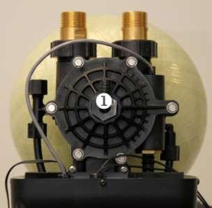
99 6 7.a 7.b r 8.a 8.b 2013 Aquion, Inc. PP-ProFlow-Rev


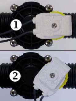

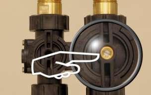
100 r r 12 r Aquion, Inc. PP-ProFlow-Rev

101 14 15.a 15.b 15.c 2013 Aquion, Inc. PP-ProFlow-Rev
Installation & Operating Instructions. Models: PF-SOF1-SIM PF-SOF1-ALT PF-SOF1-PRL PF-SOF1,5-SIM PF-SOF1,5-ALT PF-SOF1,5-PRL PF-BTA
 EN FR DE NL ES PL Installation & Operating Instructions WATER SOFTENER Instructions d Installation & Emploi ADOUCISSEUR D EAU Installation- & Gebrauchsanleitung WASSERENTHÄRTER Installatie & Gebruiksinstructies
Installation & Operating Instructions. WATER SOFTENER Instructions d Installation & Emploi. ADOUCISSEUR D EAU Installation- & Gebrauchsanleitung
 EN FR DE NL PL Installation & Operating Instructions WATER SOFTENER Instructions d Installation & Emploi ADOUCISSEUR D EAU Installation- & Gebrauchsanleitung WASSERENTHÄRTER Installatie & Gebruiksinstructies
Installation & Operating Instructions. Models: PF-SOF1-SIM PF-SOF1-ALT PF-SOF1-PRL PF-SOF1,5-SIM PF-SOF1,5-ALT PF-SOF1,5-PRL PF-BTA
 EN FR DE NL ES PL Installation & Operating Instructions WATER SOFTENER Instructions d Installation & Emploi ADOUCISSEUR D EAU Installation- & Gebrauchsanleitung WASSERENTHÄRTER Installatie & Gebruiksinstructies
WYŁĄCZNIK CZASOWY OUTDOOR TIMER
 003-582 PL WYŁĄCZNIK CZASOWY Instrukcja obsługi (Tłumaczenie oryginalnej instrukcji) Ważny! Przed użyciem uważnie przeczytaj instrukcję obsługi! Zachowaj ją na przyszłość. EN OUTDOOR TIMER Operating instructions
EN FR DE NL PL. WATER FILTER - Fe, Mn, H 2 S Instructions d Installation & Emploi. FILTRE Á EAU - Fe, Mn, H 2 S Installation- & Gebrauchsanleitung
 EN FR DE NL PL Installation & Operating Instructions WATER FILTER - Fe, Mn, H 2 S Instructions d Installation & Emploi FILTRE Á EAU - Fe, Mn, H 2 S Installation- & Gebrauchsanleitung WASSERFILTER - Fe,
LED WASHER 30x3W WHITE IP65 F
 USER MANUAL / INSTRUKCJA OBSŁUGI LED WASHER 30x3W WHITE IP65 F7200171 LED WASHER 30x3W WHITE IP65 F7200171 Table of contents 1 Introduction... 2 2 Safety information... 2 3 Product information... 2 3.1
EN FR DE NL PL. WATER FILTER - Fe, Mn, H 2 S Instructions d Installation & Emploi. FILTRE Á EAU - Fe, Mn, H 2 S Installation- & Gebrauchsanleitung
 EN FR DE NL PL Installation & Operating Instructions WATER FILTER - Fe, Mn, H 2 S Instructions d Installation & Emploi FILTRE Á EAU - Fe, Mn, H 2 S Installation- & Gebrauchsanleitung WASSERFILTER - Fe,
ZMIĘKCZACZ WODY WATER TECHNIC Strona 2. WATER SOFTENER WATER TECHNIC Page 13
 PL EN Instrukcja instalacji i uruchomienia ZMIĘKCZACZ WODY WATER TECHNIC Strona 2 Installation and operating instructions WATER SOFTENER WATER TECHNIC Page 13 High Efficient, Low Consumption Softener WSTĘP
DM-ML, DM-FL. Auxiliary Equipment and Accessories. Damper Drives. Dimensions. Descritpion
 DM-ML, DM-FL Descritpion DM-ML and DM-FL actuators are designed for driving round dampers and square multi-blade dampers. Example identification Product code: DM-FL-5-2 voltage Dimensions DM-ML-6 DM-ML-8
ZMIĘKCZACZ WODY WATER TECHNIC Strona 2. WATER SOFTENER WATER TECHNIC Page 13
 PL EN Instrukcja instalacji i uruchomienia ZMIĘKCZACZ WODY WATER TECHNIC Strona 2 Installation and operating instructions WATER SOFTENER WATER TECHNIC Page 13 High Efficient, Low Consumption Softener WSTĘP
BLACKLIGHT SPOT 400W F
 BLACKLIGHT SPOT 400W F2000339 USER MANUAL / INSTRUKCJA OBSŁUGI BLACKLIGHT SPOT 400W F2000339 Table of Contents 1 Introduction... 2 2 Safety information... 2 3 Product information... 2 3.1 Specification...
Zasady bezpieczeństwa
 2 3 Zasady bezpieczeństwa GB The door and the feeding flap must be closed when operating the machine! PL Drzwiczki i klapka szczeliny podawczej muszą być zamknięte w trakcie używania urządzenia! GB Ensure
TR18 INSTALATION MANUAL / INSTRUKCJA MONTAŻU. cart for flat displays
 INSTLTION NUL / INSTRUKCJ ONTŻU cart for flat displays WRNING: Please read this manual before the installation to ensure proper assembly. The assembly should be carried out in accordance with this manual
Klimatyzatory ścienne i kasetonowe YORK. Cennik 2013
 Klimatyzatory ścienne i kasetonowe YORK Cennik 2013 ELECTRONIC CONTROL SYSTEMS SP. Z O. O. 32-083 Balice k. Krakowa; ul. Krakowska 84 MODEL / KOMPLET YJHJZH 09 ŚCIENNY YJHJZH 12 ŚCIENNY YJHJZH 18 ŚCIENNY
Installation of EuroCert software for qualified electronic signature
 Installation of EuroCert software for qualified electronic signature for Microsoft Windows systems Warsaw 28.08.2019 Content 1. Downloading and running the software for the e-signature... 3 a) Installer
HAPPY K04 INSTRUKCJA MONTAŻU ASSEMBLY INSTRUCTIONS DO MONTAŻU POTRZEBNE SĄ DWIE OSOBY! INSTALLATION REQUIRES TWO PEOPLE! W5 W6 G1 T2 U1 U2 TZ1
 HAPPY K0 INSTRUKCJA MONTAŻU ASSEMBLY INSTRUCTIONS W Akcesoria / Fittings W W G K szt. / pcs M Ø Ø 0 Ø, Ø Ø. 0 ø8 M 8 szt. / pcs 0 szt. / pcs szt. / pcs T U U szt. / pcs szt. / pcs szt. / pcs S TZ szt.
W6636 East Avenue North, Onalaska, WI USA (608) 781-8500 Fax: (608) 783-6115 F150-80789-D-09
 781-8500 Fax: (608) 783-6115 F150-80789-D-09") W6636 East Avenue North, Onalaska, WI USA (608) 781-8500 Fax: (608) 783-6115 F150-80789-D-09 2 3 Model SPECIFICATIONS 4 Informacja o paliwie dla panstwa docelowego Gaz Plynny Panstwa docelowe Kategoria
W6636 East Avenue North, Onalaska, WI USA (608) 781-8500 Fax: (608) 783-6115 F150-80789-D-09 2 3 Model SPECIFICATIONS 4 Informacja o paliwie dla panstwa docelowego Gaz Plynny Panstwa docelowe Kategoria
DO MONTAŻU POTRZEBNE SĄ DWIE OSOBY! INSTALLATION REQUIRES TWO PEOPLE!
 1 HAPPY ANIMALS B09 INSTRUKCJA MONTAŻU ASSEMBLY INSTRUCTIONS Akcesoria / Fittings K1 M M1 ZM1 Z T G1 17 szt. / pcs 13 szt. / pcs B1 13 szt. / pcs W4 13 szt. / pcs W6 14 szt. / pcs U1 1 szt. / pcs U N1
Installation & Operating Instructions. WATERFILTER Instrukcja Instalacji i Eksploatacji FILTR WODY. Models: PF-GAC1 PF-AG1 PF-GAC1,5 PF-AG1,5
 EN FR DE NL PL Installation & Operating Instructions WATER FILTER Instructions d Installation & Emploi FILTRE À EAU Installation- & Gebrauchsanleitung WASSERFILTER Installatie & Gebruiksinstructies WATERFILTER
EN FR DE NL PL. WATER FILTER Instructions d Installation & Emploi. FILTRE À EAU Installation- & Gebrauchsanleitung
 EN FR DE NL PL Installation & Operating Instructions WATER FILTER Instructions d Installation & Emploi FILTRE À EAU Installation- & Gebrauchsanleitung WASSERFILTER Installatie & Gebruiksinstructies WATERFILTER
DO MONTAŻU POTRZEBNE SĄ DWIE OSOBY! INSTALLATION REQUIRES TWO PEOPLE!
 1 HAPPY ANIMALS SZ11 A INSTRUKCJA MONTAŻU ASSEMBLY INSTRUCTIONS Akcesoria / Fittings K1 M M1 ZM1 Z G1 szt. / pcs 0 szt. / pcs B1 6 szt. / pcs 6 szt. / pcs W6 0 szt. / pcs U1 19 szt. / pcs U 50 szt. / pcs
Instrukcja obsługi. binding machine KRIS. instruction manual. 80-393 GDAŃSK ul. Krynicka 1 tel.: (058) 55 43 555 fax: (058) 55 43 500 ODDZIAŁ:
 55 43 555 fax: (058) 55 43 500 ODDZIAŁ:") Instrukcja obsługi instruction manual 80-393 GDAŃSK ul. Krynicka 1 tel.: (058) 55 43 555 fax: (058) 55 43 500 ODDZIAŁ: 02-784 WARSZAWA ul. Janowskiego 9 tel.: (022) 648 03 48..49 fax: (022) 648 03 50 bindownica
Instrukcja obsługi instruction manual 80-393 GDAŃSK ul. Krynicka 1 tel.: (058) 55 43 555 fax: (058) 55 43 500 ODDZIAŁ: 02-784 WARSZAWA ul. Janowskiego 9 tel.: (022) 648 03 48..49 fax: (022) 648 03 50 bindownica
DO MONTAŻU POTRZEBNE SĄ DWIE OSOBY! INSTALLATION REQUIRES TWO PEOPLE!
 HAPPY ANIMALS RW08 INSTRUKCJA MONTAŻU ASSEMBLY INSTRUCTIONS Akcesoria / Fittings K M M ZM ZW G 0 szt. / pcs W szt. / pcs B szt. / pcs szt. / pcs W U 8 szt. / pcs 4 szt. / pcs U N szt. / pcs Ø3 x szt. /
User s manual for icarwash
 User s manual for icarwash BKF Myjnie Bezdotykowe Sp. z o.o. Skarbimierzyce 22 72 002 Dołuje (k. Szczecina) Skarbimierzyce, 2014.11.14 Version v0.2 Table of Contents Table of Contents Settings Login Navigation
Aktualizacja Oprogramowania Firmowego (Fleszowanie) Microprocessor Firmware Upgrade (Firmware downloading)
 Microprocessor Firmware Upgrade (Firmware downloading)") Aktualizacja Oprogramowania Firmowego (Fleszowanie) Microprocessor Firmware Upgrade (Firmware downloading) ROGER sp.j. Gościszewo 59 82-416 Gościszewo Poland tel. 055 2720132 fax 055 2720133 www.roger.pl
Aktualizacja Oprogramowania Firmowego (Fleszowanie) Microprocessor Firmware Upgrade (Firmware downloading) ROGER sp.j. Gościszewo 59 82-416 Gościszewo Poland tel. 055 2720132 fax 055 2720133 www.roger.pl
LED MAGIC BALL MP3 F
 USER MANUAL / INSTRUKCJA OBSŁUGI LED MAGIC BALL MP3 F7000623 LED MAGIC BALL MP3 F7000623 Table of contents 1 Introduction... 2 2 Safety information... 2 3 Product information... 2 3.1 Specification...
 www.irs.gov/form990. If "Yes," complete Schedule A Schedule B, Schedule of Contributors If "Yes," complete Schedule C, Part I If "Yes," complete Schedule C, Part II If "Yes," complete Schedule C, Part
B IURO B ADAWCZE DS. J AKOŚCI
 ISO 9001 Q Ref. Certif. No. PL 2 IEC SYSTEM FOR MUTUAL RECOGNITION OF TEST CERTIFICATES FOR ELECTRICAL EQUIPMENT (IECEE) CB SCHEME SYSTEME CEI D ACCEPTATION MUTUELLE DE CERTIFICATS D ESSAIS DES EQUIPEMENTS
HAPPY ANIMALS L01 HAPPY ANIMALS L03 HAPPY ANIMALS L05 HAPPY ANIMALS L07
 HAPPY ANIMALS L0 HAPPY ANIMALS L0 HAPPY ANIMALS L0 HAPPY ANIMALS L07 INSTRUKCJA MONTAŻU ASSEMBLY INSTRUCTIONS Akcesoria / Fittings K ZW W8 W7 Ø x 6 szt. / pcs Ø7 x 70 Narzędzia / Tools DO MONTAŻU POTRZEBNE
EN FR DE NL PL. MULTI PURPOSE WATER FILTER Instructions d Installation & Emploi. FILTRE D EAU MULTI-USAGE Installation- & Gebrauchsanleitung
 EN FR DE NL PL Installation & Operating Instructions MULTI PURPOSE WATER FILTER Instructions d Installation & Emploi FILTRE D EAU MULTI-USAGE Installation- & Gebrauchsanleitung MEHRZWECK WASSERFILTER Installatie
HAPPY ANIMALS L02 HAPPY ANIMALS L04 HAPPY ANIMALS L06 HAPPY ANIMALS L08
 HAPPY ANIMALS L02 HAPPY ANIMALS L04 HAPPY ANIMALS L06 HAPPY ANIMALS L08 INSTRUKCJA MONTAŻU ASSEMBLY INSTRUCTIONS Akcesoria / Fittings K O G ZW W8 W4 20 szt. / pcs 4 szt. / pcs 4 szt. / pcs 4 szt. / pcs
Strona główna > Produkty > Systemy regulacji > System regulacji EASYLAB - LABCONTROL > Program konfiguracyjny > Typ EasyConnect.
 Typ EasyConnect FOR THE COMMISSIONING AND DIAGNOSIS OF EASYLAB COMPONENTS, FSE, AND FMS Software for the configuration and diagnosis of controllers Type TCU3, adapter modules TAM, automatic sash device
099 Łóżko półpiętrowe 2080x1010(1109)x Bunk bed 2080x1010(1109)x1600 W15 INSTRUKCJA MONTAŻU ASSEMBLY INSTRUCTION
x Bunk bed 2080x1010(1109)x1600 W15 INSTRUKCJA MONTAŻU ASSEMBLY INSTRUCTION") INSTRUKCJA MONTAŻU ASSEMBLY INSTRUCTION 2 WAŻNE, ZACHOWAĆ DO PÓŹNIEJSZEGO STOSOWANIA- UWAŻNIE PRZECZYTAĆ IMPORTANT, SAVE FOR FURTHER USAGE- READ CAREFULLY INSTRUKCJA UZYTKOWANIA USER S MANUAL. Aby uniknąć
INSTRUKCJA MONTAŻU ASSEMBLY INSTRUCTION 2 WAŻNE, ZACHOWAĆ DO PÓŹNIEJSZEGO STOSOWANIA- UWAŻNIE PRZECZYTAĆ IMPORTANT, SAVE FOR FURTHER USAGE- READ CAREFULLY INSTRUKCJA UZYTKOWANIA USER S MANUAL. Aby uniknąć
SSW1.1, HFW Fry #20, Zeno #25 Benchmark: Qtr.1. Fry #65, Zeno #67. like
 SSW1.1, HFW Fry #20, Zeno #25 Benchmark: Qtr.1 I SSW1.1, HFW Fry #65, Zeno #67 Benchmark: Qtr.1 like SSW1.2, HFW Fry #47, Zeno #59 Benchmark: Qtr.1 do SSW1.2, HFW Fry #5, Zeno #4 Benchmark: Qtr.1 to SSW1.2,
Jazz EB207S is a slim, compact and outstanding looking SATA to USB 2.0 HDD enclosure. The case is
 1. Introduction Jazz EB207S is a slim, compact and outstanding looking SATA to USB 2.0 HDD enclosure. The case is made of aluminum and steel mesh as one of the coolest enclosures available. It s also small
USB firmware changing guide. Zmiana oprogramowania za przy użyciu połączenia USB. Changelog / Lista Zmian
 1 / 12 Content list / Spis Treści 1. Hardware and software requirements, preparing device to upgrade Wymagania sprzętowe i programowe, przygotowanie urządzenia do aktualizacji 2. Installing drivers needed
Instrukcja obsługi. ibind A8/A12/A15/A20. instruction manual. 80-393 GDAŃSK ul. Krynicka 1 tel.: (058) 55 43 555 fax: (058) 55 43 500
 55 43 555 fax: (058) 55 43 500") Instrukcja obsługi instruction manual 80-9 GDAŃSK ul. Krynicka tel.: (08) fax: (08) 00 ODDZIAŁ: 0-78 WARSZAWA ul. Janowskiego 9 tel.: (0) 8 0 8..9 fax: (0) 8 0 0 BindownicE ibind A8/A/A/A0 BINDING MACHINEs
Instrukcja obsługi instruction manual 80-9 GDAŃSK ul. Krynicka tel.: (08) fax: (08) 00 ODDZIAŁ: 0-78 WARSZAWA ul. Janowskiego 9 tel.: (0) 8 0 8..9 fax: (0) 8 0 0 BindownicE ibind A8/A/A/A0 BINDING MACHINEs
INSTRUCTION MANUAL. Strona 1
 INSTRUCTION MANUAL www.flash-butrym.pl Strona 1 LED SPOT LIGHT INSTRUCTION MANUAL Thank you for purchasing the LEDSPOT10W Spot light. It is a small and easy to carry unit that is simple to install. Features:
Rev Źródło:
 KamPROG for AVR Rev. 20190119192125 Źródło: http://wiki.kamamilabs.com/index.php/kamprog_for_avr Spis treści Introdcution... 1 Features... 2 Standard equipment... 4 Installation... 5 Software... 6 AVR
LED MINI DERBY 4x3W RGBW F
 USER MANUAL / INSTRUKCJA OBSŁUGI LED MINI DERBY 4x3W RGBW F7000598 LED MINI DERBY 4x3W RGBW F7000598 Table of contents 1 Introduction... 2 2 Safety information... 2 3 Product information... 2 3.1 Specification...
TECHNICAL CATALOGUE WHITEHEART MALLEABLE CAST IRON FITTINGS EE
 TECHNICAL CATALOGUE WHITEHEART MALLEABLE CAST IRON FITTINGS EE Poland GENERAL INFORMATION USE Whiteheart malleable cast iron fittings brand EE are used in threaded pipe joints, particularly in water, gas,
Céliane TM Vac 50-60Hz. 1 x 2.5 mm 2 2 x 1.5 mm 2. Max. 400 W 400 W 400 VA 400 VA. 240 Vac. Min. 40 W 40 W 40 VA 40 VA
 Céliane TM instrukcja Remotelycontrollable ściemniacza dimmer 067087 switch for all incandescent loads 670 87 ( *) 100240 Vac 5060Hz 1 x 2.5 mm 2 2 x 1.5 mm 2 240 Vac Max. 400 W 400 W 400 VA 400 VA Min.
THE RAIL RATES valid from 1st October 2015
 RAIL TARIFF This Rail Tariff is an integral part of intermodal transport arrangement service provided by PCC Intermodal S.A. and therefore it cannot be used as a standalone offer, only in combination with
G14L LPG toroidal tank
 G14L LPG toroidal tank Product Description 4-hole version of the unique STAKO patented design of the full (centre-filled) toroidal tank. The valve plate enhances the functionality of the tank compared
098 Łóżko piętrowe 2080x1010(1109)x Double bunk bed 2080x1010(1109)x1600 W15 MONTAGEANLEITUNG ASSEMBLY INSTRUCTION
x Double bunk bed 2080x1010(1109)x1600 W15 MONTAGEANLEITUNG ASSEMBLY INSTRUCTION") 098 Double bunk bed 2080x(9)x600 W5 MONTAGEANLEITUNG ASSEMBLY INSTRUCTION 2 WAŻNE, ZACHOWAĆ DO PÓŹNIEJSZEGO STOSOWANIA- UWAŻNIE PRZECZYTAĆ IMPORTANT, SAVE FOR FURTHER USAGE- READ CAREFULLY INSTRUKCJA UZYTKOWANIA
098 Double bunk bed 2080x(9)x600 W5 MONTAGEANLEITUNG ASSEMBLY INSTRUCTION 2 WAŻNE, ZACHOWAĆ DO PÓŹNIEJSZEGO STOSOWANIA- UWAŻNIE PRZECZYTAĆ IMPORTANT, SAVE FOR FURTHER USAGE- READ CAREFULLY INSTRUKCJA UZYTKOWANIA
Tychy, plan miasta: Skala 1: (Polish Edition)
") Tychy, plan miasta: Skala 1:20 000 (Polish Edition) Poland) Przedsiebiorstwo Geodezyjno-Kartograficzne (Katowice Click here if your download doesn"t start automatically Tychy, plan miasta: Skala 1:20 000
Tychy, plan miasta: Skala 1:20 000 (Polish Edition) Poland) Przedsiebiorstwo Geodezyjno-Kartograficzne (Katowice Click here if your download doesn"t start automatically Tychy, plan miasta: Skala 1:20 000
Camspot 4.4 Camspot 4.5
 User manual (addition) Dodatek do instrukcji obsługi Camspot 4.4 Camspot 4.5 1. WiFi configuration 2. Configuration of sending pictures to e-mail/ftp after motion detection 1. Konfiguracja WiFi 2. Konfiguracja
LED WALL WASHER 36x3W RGBW 3SC IP65 F
 USER MANUAL / INSTRUKCJA OBSŁUGI LED WALL WASHER 36x3W RGBW 3SC IP65 F7200168 LED WALL WASHER 36x3W RGBW 3SC IP65 F7200168 Table of contents 1 Introduction... 2 2 Safety information... 2 3 Product information...
USB firmware changing guide. Zmiana oprogramowania za przy użyciu połączenia USB. Changelog / Lista Zmian
 1 / 14 Content list / Spis Treści 1. Hardware and software requirements, preparing device to upgrade Wymagania sprzętowe i programowe, przygotowanie urządzenia do aktualizacji 2. Installing drivers and
Nazwa firmy: Autor: Telefon: Dane:
 Pozycja Ilość Opis 1 MSS.11.3.2 Nr katalogowy: 979127 Uwaga! Zdjęcie produktu może się różnic od aktualnego Supplied as complete unit ready for installation, the Multilift consist of a fully integrated
 www.irs.gov/form990. If "Yes," complete Schedule A Schedule B, Schedule of Contributors If "Yes," complete Schedule C, Part I If "Yes," complete Schedule C, Part II If "Yes," complete Schedule C, Part
Pokrywa kołnierza ø120 z tuleją 1½ oraz ø180 z tuleją 2. Flange Cover ø120 with 1 ½ Sleeve and ø180 with 2 Sleeve. Instrukcja montażu
 Pokrywa kołnierza ø0 z tuleją ½ oraz ø80 z tuleją Instrukcja montażu Flange Cover ø0 with ½ Sleeve and ø80 with Sleeve Installation Manual 5.0.06 576 INSTRUKCJA MONTAŻU Spis treści PL. INFORMACJE OGÓLNE....
Selfie Monopod MA426. Instrukcja obsługi User s Manual
 Selfie Monopod MA426 Instrukcja obsługi User s Manual PL Selfie Monopod Przeczytaj wszystkie instrukcje przed użyciem oraz zachowaj te informacje do wykorzystania w przyszłości. Zestaw: 1x mobile phone
LED PAR 56 7x10 4in1 RGBW F
 USER MANUAL / INSTRUKCJA OBSŁUGI LED PAR 56 7x10 4in1 RGBW F7100311 LED PAR 56 7x10W 4in1 RGBW F7100311 Table of Contents 1 Introduction... 2 2 Safety information... 2 3 Product information... 2 3.1 Specification...
ORIGINAL USER MANUAL. Remote Control Z-Wave NC 896-GB IU/ZRH12/ /F
 WARRANTY The manufacturer guarantees correct device functioning. It also undertakes to repair or replace faulty device if damage is a result of material or structural faults. The warranty period is 2 months
Stacja filtracyjna MCP-16RC
 Kompaktowy filtr kartridżowy, czyszczony impulsami sprężonego powietrza jest kompaktowym filtrem kartridżowym do lokalnego oczyszczania powietrza w pomieszczeniach, gdzie jest możliwy odzysk powietrza.
LED PAR 56 7*10W RGBW 4in1 SLIM
 LED PAR 56 7*10W RGBW 4in1 SLIM USER MANUAL Attention: www.flash-butrym.pl Strona 1 1. Please read this specification carefully before installment and operation. 2. Please do not transmit this specification
Hippo Boombox MM209N CD. Instrukcja obsługi User s Manual
 Hippo Boombox Instrukcja obsługi User s Manual OPIS PRZYCISKÓW: PL ON-OFF/MODE: 1. Włącz on/off: Naciśnij przycisk, aby włączyć urządzenie. Przytrzymaj dłużej, aby wyłączyć. 2. MODE: Wybierz źródło sygnału:
LED PAR 18x10W RGBW 4in1 Aluminum single cast II ver. F
 LED PAR 18x10W RGBW 4in1 Aluminum single cast II ver. F71000269 USER MANUAL / INSTRUKCJA OBSŁUGI LED PAR 18x 10W RGBW 4in1 Aluminium single cast II ver. F71000269 Table of Contents 1 Introduction... 2
Installation & Operating Instructions. MULTI-PURPOSE WATER FILTER Instructions d Installation & Emploi MULTIFUNKCYJNY FILTR WODY
 EN FR DE NL PL Installation & Operating Instructions MULTI-PURPOSE WATER FILTER Instructions d Installation & Emploi FILTRE D EAU MULTI-USAGE Installation- & Gebrauchsanleitung MEHRZWECK WASSERFILTER Installatie
Car MP3 Player MM211. Aby zapewnić prawidłową obsługę sprzętu zapoznaj się dokładnie z instrukcją i zachowaj ją na przyszłość.
 Car MP3 Player MM211 Aby zapewnić prawidłową obsługę sprzętu zapoznaj się dokładnie z instrukcją i zachowaj ją na przyszłość. To ensure proper use of this product please read this User s Manual carefully
Zarządzanie sieciami telekomunikacyjnymi
 SNMP Protocol The Simple Network Management Protocol (SNMP) is an application layer protocol that facilitates the exchange of management information between network devices. It is part of the Transmission
BARIERA ANTYKONDENSACYJNA
 Skład Obróbka Parametry techniczne BARIERA ANTYKONDENSACYJNA Lama "Lama" sp. z o.o. sp. k Właściwość Metoda badania Wartość Jednostka włóknina poliestrowa + klej PSA + folia polietylenowa Samoprzylepna
Instrukcja konfiguracji usługi Wirtualnej Sieci Prywatnej w systemie Mac OSX
 UNIWERSYTETU BIBLIOTEKA IEGO UNIWERSYTETU IEGO Instrukcja konfiguracji usługi Wirtualnej Sieci Prywatnej w systemie Mac OSX 1. Make a new connection Open the System Preferences by going to the Apple menu
USB firmware changing guide. Zmiana oprogramowania za przy użyciu połączenia USB. Changelog / Lista Zmian
 1 / 9 Content list / Spis Treści 1. Hardware and software requirements, preparing device to upgrade Wymagania sprzętowe i programowe, przygotowanie urządzenia do aktualizacji 2. Installing drivers and
LED PAR 64 7x10W RGBW 4in1 ABS Remote Control F
 LED PAR 64 7x10W RGBW 4in1 ABS Remote Control F7100303 USER MANUAL / INSTRUKCJA OBSŁUGI LED PAR 64 7x10W RGBW 4in1 ABS Remote Control F7100303 Table of Contents 1 Introduction... 2 2 Safety information...
FOG MACHINE FLZ-1500 DMX+ RE F
 FOG MACHINE FLZ-1500 DMX+ RE F5100336 USER MANUAL / INSTRUKCJA OBSŁUGI FOG MACHINE FLZ-1500 DMX+ RE F5100336 Table of Contents 1 Introduction... 2 2 Safety information... 2 3 Product information... 3 3.1
LED PAR Set 4x PAR 36 12x3W F
 USER MANUAL / INSTRUKCJA OBSŁUGI LED PAR Set 4x PAR 36 12x3W F7100306 Table of contents 1 Introduction... 2 2 Safety information... 2 3 Specification... 2 4 Installation... 3 5 Connections... 3 5.1 Connecting
s s s SYSTEMY UZDATNIANIA WODY s s s s INWATER Sp. z o.o. GŁOWICE, CZEŚCI WYMIENNE GŁOWIC, AKCESORIA Cennik 2/4-2015 ważny od 11.05.
 s s s SYSTEMY UZDATNIANIA WODY s s s s s s s s s s INWATER Sp. z o.o. GŁOWICE, CZEŚCI WYMIENNE GŁOWIC, AKCESORIA s Cennik 2/4-2015 ważny od 11.05.2015 SPIS TREŚCI 1. GŁOWICE... 3 1.1. GŁOWICE 255... 3
TACHOGRAPH SIMULATOR DTCOSIM
 TACHOGRAPH SIMULATOR DTCOSIM Service Manual USB-KSIM interface General description The simulator is a device that is used as a replacement for tachograph in the vehicle where the tachograph is not mandatory,
INSTRUKCJA MONTAŻU MARBO E SPORT LISTA CZĘŚCI (PARTS LIST) (ASSEMBLY INSTRUCTION) MH-W102 NR CZĘŚCI (PART NO.) ILOŚĆ (QUANTITY) OPIS (DESCRIPTION)
 (ASSEMBLY INSTRUCTION) MH-W102 NR CZĘŚCI (PART NO.) ILOŚĆ (QUANTITY) OPIS (DESCRIPTION)") LISTA CZĘŚCI (PARTS LIST) NR CZĘŚCI (PART NO.) ILOŚĆ (QUANTITY) OPIS (DESCRIPTION) 1 ŚRUBA (HEX BOLT) x70 6 ŚRUBA (HEX BOLT) 0 3 ŚRUBA (CARRIAGE BOLT) 5 INSTRUKCJA MONTAŻU (ASSEMBLY INSTRUCTION) MH-W10
LISTA CZĘŚCI (PARTS LIST) NR CZĘŚCI (PART NO.) ILOŚĆ (QUANTITY) OPIS (DESCRIPTION) 1 ŚRUBA (HEX BOLT) x70 6 ŚRUBA (HEX BOLT) 0 3 ŚRUBA (CARRIAGE BOLT) 5 INSTRUKCJA MONTAŻU (ASSEMBLY INSTRUCTION) MH-W10
MM210. Instrukcja obsługi User s Manual
 Chilli Boombox Instrukcja obsługi User s Manual OPIS PRZYCISKÓW: PL ON-OFF/MODE: 1. Włącz on/off: Naciśnij przycisk, aby włączyć urządzenie. Przytrzymaj dłużej, aby wyłączyć. 2. MODE: Wybierz źródło sygnału:
LED PAR 18x 10W RGBW 4in1 Aluminium single cast v.iii F B
 LED PAR 18x 10W RGBW 4in1 Aluminium single cast v.iii F7000048B USER MANUAL / INSTRUKCJA OBSŁUGI LED PAR 18x 10W RGBW 4in1 Aluminium single cast v.iii F7000048B Table of Contents 1 Introduction... 2 2
Installez un certificat ssl par l'intermédiaire du CLI sur un ESA
 Installez un certificat ssl par l'intermédiaire du CLI sur un ESA Contenu Introduction Prerequistes Installez un certificat ssl Informations connexes Introduction Ce document décrit comment installer un
Karpacz, plan miasta 1:10 000: Panorama Karkonoszy, mapa szlakow turystycznych (Polish Edition)
") Karpacz, plan miasta 1:10 000: Panorama Karkonoszy, mapa szlakow turystycznych (Polish Edition) J Krupski Click here if your download doesn"t start automatically Karpacz, plan miasta 1:10 000: Panorama
Karpacz, plan miasta 1:10 000: Panorama Karkonoszy, mapa szlakow turystycznych (Polish Edition) J Krupski Click here if your download doesn"t start automatically Karpacz, plan miasta 1:10 000: Panorama
Zakopane, plan miasta: Skala ok. 1: = City map (Polish Edition)
") Zakopane, plan miasta: Skala ok. 1:15 000 = City map (Polish Edition) Click here if your download doesn"t start automatically Zakopane, plan miasta: Skala ok. 1:15 000 = City map (Polish Edition) Zakopane,
Zakopane, plan miasta: Skala ok. 1:15 000 = City map (Polish Edition) Click here if your download doesn"t start automatically Zakopane, plan miasta: Skala ok. 1:15 000 = City map (Polish Edition) Zakopane,
LED PAR 64 18x10W RGBW 4in1 IP64 PFC F
 LED PAR 64 18x10W RGBW 4in1 IP64 PFC F7100305 USER MANUAL / INSTRUKCJA OBSŁUGI LED PAR 64 18x10W RGBW 4in1 IP65 PFC F7100305 Table of Contents 1 Introduction... 2 2 Safety information... 2 3 Product information...
LED WASHER RGB IP34 F
 USER MANUAL / INSTRUKCJA OBSŁUGI LED WASHER RGB IP34 F7200182 LED WASHER RGB IP34 F7200182 Table of contents 1 Introduction... 2 2 Safety information... 2 3 Product information... 2 3.1 Specification...
 !850016! www.irs.gov/form8879eo. e-file www.irs.gov/form990. If "Yes," complete Schedule A Schedule B, Schedule of Contributors If "Yes," complete Schedule C, Part I If "Yes," complete Schedule C,
LED PAR 64 18x12W RGBW 4in1 ZOOM IP65 F
 LED PAR 64 18x12W RGBW 4in1 ZOOM IP65 F7100250 USER MANUAL / INSTRUKCJA OBSŁUGI LED PAR 64 18x12W RGBW 4in1 ZOOM IP65 F7100250 Table of contents 1 Introduction... 2 2 Safety information... 2 2.1 Specification...
LED PAR 18x10W RGBW 4in1 IP65 F
 LED PAR 18x10W RGBW 4in1 IP65 F7100310 USER MANUAL / INSTRUKCJA OBSŁUGI LED PAR 18x10W RGBW 4in1 IP65 F7100310 Table of contents 1 Introduction... 2 2 Safety information... 2 2.1 Specification... 2 3 Installation...
OpenPoland.net API Documentation
 OpenPoland.net API Documentation Release 1.0 Michał Gryczka July 11, 2014 Contents 1 REST API tokens: 3 1.1 How to get a token............................................ 3 2 REST API : search for assets
LED MOVING HEAD 60W F
 USER MANUAL / INSTRUKCJA OBSŁUGI LED MOVING HEAD 60W F1700044 LED MOVING HEAD 60W F1700044 Table of Contents 1 Introduction... 2 2 Safety information... 2 3 Product information... 2 3.1 Specification...
LED PAR 56 Slim 18X3W RGB Aura F7000253a
 USER MANUAL / INSTRUKCJA OBSŁUGI LED PAR 56 Slim 8XW RGB Aura F700025a LED PAR 56 Slim 8XW RGB Aura F700025a Table of contents Introduction... 2 2 Safety information... 2 Product information... 2. Specification...
LED PAR 64 18x10W 4in1 CLASSIC F
 LED PAR 64 18x10W 4in1 CLASSIC F7100309 USER MANUAL / INSTRUKCJA OBSŁUGI LED PAR 64 18x10W 4in1 CLASSIC F7100309 Table of Contents 1 Introduction... 2 2 Safety information... 2 3 Product information...
USB 2.0 cable Tool package (Screwdriver*1+ Screw for aluminum body*3 + Screws for HDD and the PCB board*5) User s manual Carry Bag
 User s manual Carry Bag") User s Manual Page 1 A. Package Content Brick EB208S HDD Enclosure USB 2.0 cable Tool package (Screwdriver*1+ Screw for aluminum body*3 + Screws for HDD and the PCB board*5) User s manual Carry Bag B.
User s Manual Page 1 A. Package Content Brick EB208S HDD Enclosure USB 2.0 cable Tool package (Screwdriver*1+ Screw for aluminum body*3 + Screws for HDD and the PCB board*5) User s manual Carry Bag B.
LUXBUD - TERMOSTAT OCC 2
 INSTRUKCJA PROGRAMOWANIA LUXBUD - TERMOSTAT OCC 2 1. Wstęp Programowalny regulator temperatury OCC2 służy do załączania obwodu grzejnego o zadanych porach, w poszczególne dni tygodnia. Modyfikacji programu
LED STROBE COB White 200W P
 USER MANUAL / INSTRUKCJA OBSŁUGI LED STROBE COB White 200W P9700001 LED STROBE COB White 200W P9700001 Table of contents 1 Introduction... 2 2 Safety information... 2 3 Product information... 2 3.1 Features...
METHOD 2 -DIAGNOSTIC OUTSIDE
 VW MOTOMETER BOSCH METHOD 1 - OBD 2 METHOD 2 -DIAGNOSTIC OUTSIDE AFTER OPERATION YOU MUST DISCONECT ACU OR REMOVE FUSE FOR RESTART ODOMETER PO ZROBIENIU LICZNIKA ZDJĄĆ KLEMĘ LUB WYJĄĆ 2 BEZPIECZNIKI OD
Stargard Szczecinski i okolice (Polish Edition)
") Stargard Szczecinski i okolice (Polish Edition) Janusz Leszek Jurkiewicz Click here if your download doesn"t start automatically Stargard Szczecinski i okolice (Polish Edition) Janusz Leszek Jurkiewicz
Stargard Szczecinski i okolice (Polish Edition) Janusz Leszek Jurkiewicz Click here if your download doesn"t start automatically Stargard Szczecinski i okolice (Polish Edition) Janusz Leszek Jurkiewicz
EN FR DE NL PL. WATER FILTER - NO 3 Instructions d Installation & Emploi. FILTRE D EAU - NO 3 Installation- & Gebrauchsanleitung
 EN FR DE NL PL Installation & Operating Instructions WATER FILTER - NO 3 Instructions d Installation & Emploi FILTRE D EAU - NO 3 Installation- & Gebrauchsanleitung WASSERFILTER - NO 3 Installatie & Gebruiksinstructies
Rainbow Eye Bluetooth Speaker MA417 User s Manual
 Rainbow Eye Bluetooth Speaker MA417 User s Manual Opis funkcji: INSTRUKCJA OBSŁUGI Wbudowany Bluetooth 2.1 + bezprzewodowy moduł EDR Dzwięk audio przez Bluetooth, perfekcyjna jakość dzwięku oraz efekt
Urzadzenie Gwintujace ` Technologia Direct Drive
 Urzadzenie Gwintujace z Bezposrednim ` ' Napedem ` Technologia irect rive ` Opatentowane in made l y it a TAP IRECT RIVE, NOWE URZAZENIE BORIGNON. ' ' ' '. / / Nowa technologia irect rive / Nowy panel
VW3A7703 Akcesoria VW3A Rezystor hamowania IP20 28 Ohm 200W
 Dane produktu Charakterystyki Uzupełnienie Przyłącza elektryczne VW3A7703 Akcesoria VW3A Rezystor hamowania IP20 28 Ohm 200W Główne Gama produktów Typ produktu Altivar ATV61 rezystor hamujący ATV71 rezystor
Inquiry Form for Magnets
 Inquiry Form for Magnets Required scope of delivery: Yes No - Cross-beams - Magnets - Supply and Control System - Emergency supply system, backup time min - Cable drum with cable - Plug-in connections
LED PAR 36 12x3W RGBW F
 USER MANUAL / INSTRUKCJA OBSŁUGI LED PAR 36 12x3W RGBW F7000251 LED PAR 36 12x3W RGBW F7000251 Table of contents 1 Introduction... 2 2 Safety information... 2 3 Product information... 2 3.1 Specification...
Rev Źródło:
 KAmduino UNO Rev. 20190119182847 Źródło: http://wiki.kamamilabs.com/index.php/kamduino_uno Spis treści Basic features and parameters... 1 Standard equipment... 2 Electrical schematics... 3 AVR ATmega328P
LED WALL WASHER 9x10W RGBW 4in1 DMX WIFI + ACU IP65 F a
 LED WALL WASHER 9x10W RGBW 4in1 DMX WIFI + ACU IP65 F7001013a USER MANUAL / INSTRUKCJA OBSŁUGI LED WALL WASHER 9x10W RGBW 4in1 DMX WIFI + ACU IP65 F7001013a Table of contents 1 Introduction... 2 2 Safety
1113NG 487. Importer. Assembly Instructions. Instrukcja Montażu 66 GEYZ
 1113NG 487 Importer www.ogrodosfera.pl Assembly Instructions Instrukcja Montażu 66 GEYZ 1 2 3 ASSEMBLY INSTRUCTIONS (ENGLISH). Before starting, read through the assembly instructions carefully. Check thoroughly
Zwora Yale US06. Yale seria US kg. Zastosowanie. Właściwości. Parametry techniczne
 Zwora Yale US06 Yale seria US06 270 kg Zastosowanie Zwory serii US06 przeznaczone są do realizowania kontroli dostępu w pomieszczeniach wymagających podstawowej ochrony np. drzwi wewnętrzne. Właściwości