User s manual NV-MTX328
|
|
|
- Renata Chmiel
- 8 lat temu
- Przeglądów:
Transkrypt
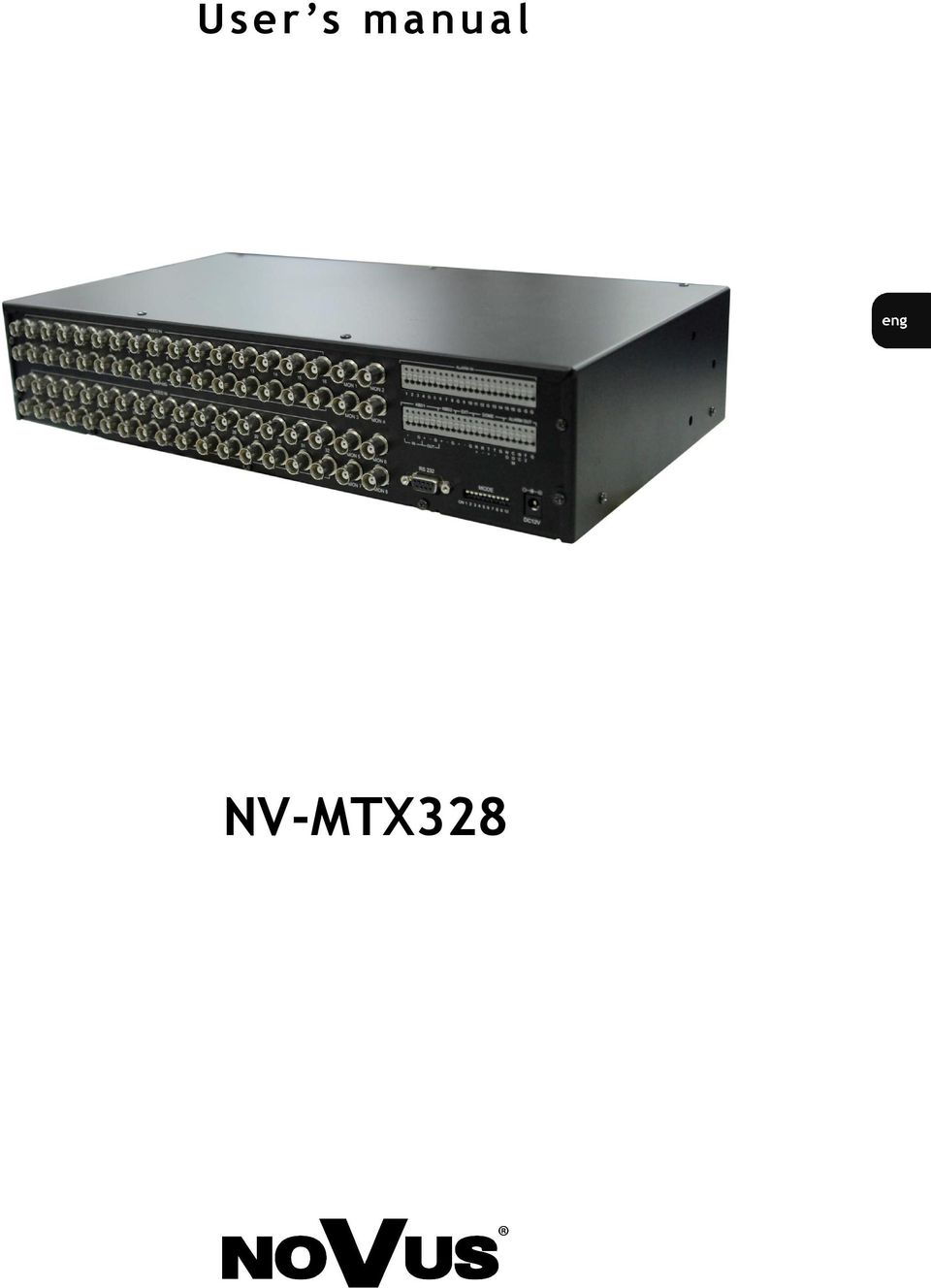
1 User s manual NV-MTX328
2 NV-MTX328 - User s manual, ver. 1.0 INFORMATION EMC (2004/108/EC) and LVD (2006/95/EC ) Directives CE Marking Our products are manufactured to comply with requirements of following directives and national regulations implementing the directives: Electromagnetic compatibility EMC 2004/108/EC. Low voltage LVD 2006/95/EC with further amendment. The Directive applies to electrical equipment designed for use with a voltage rating of between 50VAC and 1000VAC as well as 75VDC and 1500VDC. WEEE Directive 2002/96/EC Information for users who want to get rid of electrical and electronic appliances This product is marked according to the European Directive on Waste Electrical and Electronic Equipment (2002/96/EC) and further amendments. By ensuring this product is disposed of correctly, you will help to prevent potential negative consequences for the environment and human health, which could otherwise be caused by inappropriate waste handling of this product. The symbol on the product, or the documents accompanying the product, indicates that this appliance may not be treated as household waste. It shall be handed over to the applicable collection point for the waste electrical and electronic equipment for recycling purpose. For more information about recycling of this product, please contact your local authorities, your household waste disposal service or the shop where you purchased the product. RoHS Directive 2002/95/EC Information concerning limitation of the use of dangerous substances in the electrical and electronic appliances. Out of concern for human health protection and friendly environment, we assure that our products falling under RoHS Directive regulations, regarding the restriction of the use of hazardous substances in electrical and electronic equipment, have been designed and manufactured in compliance with the above mentioned regulation. Simultaneously, we claim that our products have been tested and do not contain hazardous substances whose exceeding limits could have negative impact on human health or natural environment. Information The device, as a part of professional CCTV system used for surveillance and control, is not designed for self installation in households by individuals without technical knowledge. The manufacturer is not responsible for defects and damages resulting from improper or inconsistent with user s manual installation of the device in the system. NOVUS Security Sp. z o.o., All rights reserved 2

3 NV-MTX328 - User s manual, ver. 1.0 SAFETY REQUIREMENTS SAFETY REQUIREMENTS 1. Prior to undertaking any action please consult the following manual and read all the safety and operating instructions before starting the device. 2. Please keep this manual for the lifespan of the device in case referring to the contents of this manual is necessary; 3. All the safety precautions referred to in this manual should be strictly followed, as they have a direct influence on user s safety as well as durability and reliability of the device; 4. All actions conducted by the servicemen and users must be accomplished in accordance with the user s manual; 5. The device should be disconnected from power sources during maintenance procedures; 6. Usage of additional devices and components neither provided nor recommended by the producer is forbidden; 7. Device should be supplied only from a power sources whose parameters are in accordance with those specified by the producer in the matrix switcher s technical datasheet. Therefore, it is forbidden to supply the matrix switcher from a power sources with unknown parameters, unstable or not meeting producer s requirements; 8. Signal cables should be placed in a way excluding the possibility of damaging them by accident. Special attention must be paid to cables getting from the matrix switcher and connecting the power supply; 9. Electric installation supplying the device should be designed to meet the specifications given by the producer in such a way that overloading is impossible; 10. User cannot repair or upgrade the equipment himself. All maintenance actions and repairs should be conducted only by qualified service personnel; 11. Unplug the matrix switcher from the power source immediately and contact the proper maintenance department in case of: Damages to the power cord or to the plug itself; Liquids getting inside the device or exposure to strong mechanical shock; Device behaves in a way not described in the manual and all adjustments approved by the manufacturer and possible to apply by user himself, seem not to have any effect; Matrix Switcher is damaged; A typical behaviour of the matrix switcher components may be seen (heard). 12. In necessity of repairs attention to using only original replacement parts (with their parameters in accordance with those specified by the producer) should be paid. Non-licensed service and non-genuine replacement parts may cause fire or electrocution; 13. After maintenance activities tests should be run to ensure proper operation of all the functional components of the device. Warning! PRIOR TO UNDERTAKING ANY ACTION THAT IS NOT PROVISIONED FOR THE GIVEN PRODUCT IN ITS USER S MANUAL AND OTHER DOCUMENTS DELIVERED WITH THE PRODUCT, OR THAT ARISES FROM THE NORMAL APPLICATION OF THE PRODUCT, ITS MANUFACTURER MUST BE CONTACTED OR THE RESPONSIBILITY OF THE MANUFACTURER FOR THE RESULTS OF SUCH AN ACTION SHALL BE EXCLUDED. Information Data included in the following user s manual is up to date at the time of printing. Novus Security Sp z o.o. holds exclusive rights to modify this manual. The producer reserves the rights for device specification modification and change in the design without prior notice. NOVUS Security Sp. z o.o., All rights reserved 3

4 NV-MTX328 - User s manual, ver. 1.0 TABLE OF CONTENTS 1. FOREWORD INFORMATION General characteristics NV-MTX328 technical specification PACKAGE CONTENTS MATRIX OVERVIEW Dip Switch Mode Settings and RS232 Assignment Communication Port Termination CONFIGURATION OF MATRIX SYSTEM Configuration of Single Matrix System Configuration of Parallel Matrix System Configuration of Master-slave Matrix System MATRIX SWITCHER SETUP Main menu Camera Monitor Camera title edit Monitor title edit OSD position Time and Date Port Master matrix setup Master video-in configuration Function Group Sequence Macro Event timer Alarm Auxiliary External alarm setup Camera alarm setup VLS and Cam alarm setup Slave matrix alarm setup Alarm history System Password edit Dome databank System information CONECTING KEYBOARD TO MATRIX SYSTEM Connecting NV-KBD 70 to Matrix NV-MTX Slave keyboard setting OPERATION INSTRUCTIONS Matrix Selection Monitor Selection Video input Selection Camera Selection DVR Selection Dome camera Pan/Tilt/Zoom Dome camera Lens control, Focus/Iris Operating dome camera functions Operating groups Operating sequences Operating macros Alarms Setup matrix switcher menu NOVUS Security Sp. z o.o., All rights reserved 4

5 NV-MTX328 - User s manual, ver. 1.0 FOREWORD INFORMATION 1. General characteristics NV-MTX328 matrix switcher has 32 video inputs and 8 monitor outputs with external alarm function. It is capable of switching videos and providing remote control functions from keyboard controller for a variety of external devices such as dome cameras and DVRs. A combination of 5 matrix switchers comprises a master-slave matrix system (128x8) using its extension ports. The parallel connection mode of matrix for many input-output videos is also supported. 32 video inputs with video looping and 8 monitor outputs with OSD function. Up to 32 devices: dome cameras or DVR are controllable via multi protocol with keyboard controller. RS485, RS422 selectable port for dome camera control. RS485 port for external devices like DVR and keyboard. RS232 port for DVR control or PC connection. Using 16 matrix switchers, 512x128 parallel matrix system connections can be configured. Using 5 matrix switchers, 128x8 master slave matrix system connections can be configured. Max 8 keyboards supported with 2 keyboard communication ports. Battery backed-up clock displays real time on the monitor-out. 16 external alarm inputs and 2 alarm outputs supported. Program and recall up to 80 sequence, 80 group, 80 macro functions Program up to 80 timer events. Menu password is supported for higher security. Power source DC12V input. NOVUS Security Sp. z o.o., All rights reserved 5

6 NV-MTX328 - User s manual, ver. 1.0 TECHNICAL SPECIFICATION 1.2. NV-MTX328 technical specification Model NV-MTX328 Communications RS-485/422/232 baud rate: 2400 ~38400 bps (default:9600bps) Video Input 32,Composite video 1Vp-p Video output 8,Composite video 1Vp-p Video Impedance 75 Ohm unbalanced, Inputs and Outputs S/N Ratio - 55dB RMS typical Alarm input 16 inputs with individual polarity selection. Alarm output One relay output : NO and NC contacts with shared common (1.0A /24VDC, resistive only) One output : TTL/CMOS ( Active High or Low selectable) Input Voltage 12 VDC Power Consumption 12 W Operating temperature 0C to 50C Dimension (Unit : mm) 432x88x310 Unit Weight Approx 4.2 kg NOVUS Security Sp. z o.o., All rights reserved 6

7 NV-MTX328 - User s manual, ver. 1.0 PACKAGE CONTENTS 2. Package contents Please unpack the device carefully. After unpacking please ensure that package contains the following items. NV-MTX328 user s manual Rack mounting bracket 12 VDC Power supply If any of the listed equipment has been damaged during transport or if package is incomplete, the contents of package should be packed back to the original box. Contact local NOVUS distributor for further assistance. WARNING! If the device was brought in from an area with lower ambient temperature, please wait for the device to reach current ambient temperature. Please do not power on the device immediately after bringing it from a colder place. Water vapor condensation may cause short-circuits and damage to the device as a result. NOVUS Security Sp. z o.o., All rights reserved 7

8 NV-MTX328 - User s manual, ver. 1.0 MATRIX OVERVIEW Rear view of the matrix switcher CONNECTOR USAGE 01~32 CAMERA VIDEO-IN (TOP) AND LOOP-THROUGH VIDEO (BOTTOM) MON1~MON8 MONITOR VIDEO-OUT WITH OSD FUNCTION KBD1 KBD2 CASCADE RS485 PORT FOR GLOBAL KEYBOARD INPUT OR, CONTROL BUS FOR MULTI MATRIX CONNECTION RS485 PORT FOR LOCAL KEYBOARD INPUT EXT RS485 PORT FOR EXTERNAL DEVICE (DVR, KBD) DOME RS232 ALARM-IN ALARM-OUT DC12V DOME CAMERA CONTROL PORT, RS485(T+ T- G) / RS422(R+ R- T+ T- G) RS232 PORT, PC CONNECTION 16 ALARM INPUTS, NO / NC MODE SELECTABLE 2 ALARM OUTPUTS, 1 RELAY-OUT(F1) / 1 TTL-OUT(F2) FOR POWER SUPPLY NOVUS Security Sp. z o.o., All rights reserved 8
 DOME RS232 ALARM-IN ALARM-OUT DC12V DOME CAMERA CONTROL PORT, RS485(T+ T- G) / RS422(R+ R- T+ T- G) RS232 PORT, PC CONNECTION 16 ALARM")
9 NV-MTX328 - User s manual, ver. 1.0 MATRIX OVERVIEW 3.1. Dip Switch Mode Settings and RS232 Assignment Set the switches according to your configuration. DO NOT CHANGE MODE SETTING AFTER INSTALLATION! Dip Switch Mode Setting No Setting Description Dip SW Matrix ID Setting Matrix ID 1~4 ON OFF Matrix ID (1~16) OFF OFF OFF OFF 1, MASTER 5 ON OFF Video format PAL Video format - NTSC OFF OFF OFF ON 2 OFF OFF ON OFF 3 6 ON OFF Reserved OFF OFF ON ON 4 OFF ON OFF OFF ON OFF ON OFF ON OFF ISP program update on ISP program update off KBD1 port termination on KBD1 port termination off DOME port RS422 termination on DOME port RS422 termination off OFF ON OFF ON 6 OFF ON ON OFF 7 OFF ON ON ON 8 ON OFF OFF OFF 9 ON OFF OFF ON 10 ON OFF ON OFF 11 ON OFF ON ON 12 ON ON OFF OFF ON OFF DOME port RS422, RS485 termination on DOME port RS422, RS485 termination off ON ON OFF ON 14 ON ON ON OFF 15 ON ON ON ON 16 To connect matrix switcher to PC use NULL modem RS232 port pin assignment Pin Discription 2 RX 3 TX 5 GND 1,4, 6~9 No connection NOVUS Security Sp. z o.o., All rights reserved 9


10 NV-MTX328 - User s manual, ver. 1.0 MATRIX OVERVIEW 3.2. Communication Port Termination The first and last devices in an installation (KBD1 cascade connection, DOME RS422) must have their data line terminated by setting the Dip-switch. Without proper termination, control signal errors may occur. The examples of termination are shown below. WARNING: Daisy chain connection topology needs to be strictly followed when using aforementioned connection. One line (up to 1200m) with additional short taps (up to 1,5m) is possible using this method. When using star topology please use active protocol distributor, e.g. NVPT-016DD. NOVUS Security Sp. z o.o., All rights reserved 10

11 NV-MTX328 - User s manual, ver. 1.0 CONFIGURATION OF MATRIX SYSTEM 4. CONFIGURATION OF MATRIX SYSTEM 4.1. Configuration of Single Matrix System. Before power on, connect devices as shown on diagram above and set up dip switch to MASTER (ID 1). In single connection mode, user can control up to 32 cameras or DVR. 1. Connect video line of camera to VIDEO IN connector and communication line to DOME terminal. 2. Connect monitor to MON connector. 3. Connect video input of the DVR to LOOPING connector and video output to VIDEO IN. Connect communication line of DVR to EXT terminal or RS232 connector. 4. Connect keyboards to IN of KBD1 or KBD2 terminals. Only one master keyboard (up to 4 with 3 slaves) is available per terminal, exceeding that limit may damage the matrix. OUT of KBD1 terminal is not available in single matrix connection mode. Up to 4 keyboards including slave keyboard can be connected to each keyboard terminals. 5. Connect alarm input line to ALARM IN terminal and input line of alarm device to ALARM OUT terminal. 6. Setup mode with dip switch. If dip switch setting is changed when the system is running, the matrix switcher needs to be rebooted for initialization. 7. Connect DC12V power line to DC jack and turn on matrix power. NOVUS Security Sp. z o.o., All rights reserved 11
 is available per terminal, exceeding that limit may damage the matrix.")
12 NV-MTX328 - User s manual, ver. 1.0 CONFIGURATION OF MATRIX SYSTEM 4.2. Configuration of Parallel Matrix System PARALLEL 512x128. Before power on, connect devices as shown below and set up dip switch appropriately. In parallel matrix connection mode, user can control matrix switcher like single matrix mode via KBD2 keyboard terminal, and all matrix switcher can be controlled with keyboards via KBD1 terminal. As a result, user can control up to cameras or DVR with 16 matrix switchers. Connect main keyboard to IN of KBD1 terminal and connect OUT of KBD1 to IN of other matrix s KBD1 terminal. Only one main keyboard is allowed in the whole system, setting more than one may damage the switcher. NOVUS Security Sp. z o.o., All rights reserved 12

13 NV-MTX328 - User s manual, ver. 1.0 CONFIGURATION OF MATRIX SYSTEM 1. Connect video line of camera to VIDEO IN connector and communication line to DOME terminal. 2. Connect monitor to MON connector. 3. Connect video input of DVR to LOOPING connector and video output to VIDEO IN. Connect communication line of DVR to EXT terminal or RS232 connector. 4. Connect main keyboard to IN of KBD1 terminal. And connect OUT of KBD1 to IN of other matrix s KBD1 terminal. Refer to diagram on previous page if connecting further matrixes is required. Main master keyboard must be only one (up to 4 with 3 slaves). 5. Connect local keyboard to KBD2 terminal. 6. Connect alarm input line to ALARM IN terminal and input line of alarm device to ALARM OUT terminal. 7. Setup mode with dip switch. ID of each matrix must be unique, otherwise matrix may be damaged. If dip switch setting is changed when the system is running, the matrix switcher has to be rebooted for initialization. 8. Connect DC12V power line to DC jack and turn on matrix power Configuration of Master-slave Matrix System MASTER SLAVE 128x8 Before power on, connect devices according to the diagram and set up dip switch. In masterslave matrix connection mode, one master matrix is necessary. Set the ID of master matrix to 1. Only one master matrix is allowed in the whole system, setting more than one may damage the switcher. In master-slave connection mode user can control all matrix switcher via KBD2 or EXT keyboard terminal and monitor videos from slave matrix. As a result, user can control up to 128 devices like camera or DVR with 5 matrix switchers including master. KBD1 terminal is assigned to control bus so that no keyboard can be connected. 1. In the case of slave matrix, connect video line of camera to VIDEO IN connector and communication line to DOME terminal. 2. Connect MON1~8 line of slave matrix to VIDEO IN connector of master matrix. All monitor lines of slave matrix should be connected to video-in of master matrix in turn, otherwise master matrix won t be able to display picture from monitors connected to slave matrix. 3. Connect monitor to MON of master matrix. 4. In the case of slave matrix, connect video input of the DVR to LOOP-THROUGH connector and video output to VIDEO IN. Connect communication line of DVR to EXT terminal or RS232 connector. 5. Connect OUT of master matrix s KBD1 terminal to IN of slave s KBD1 terminal. Refer to diagram if needed, so all matrixes are connected. No keyboard must be connected to KBD1 terminal. 6. Connect keyboard to KBD2 or EXT terminal of master matrix. Only one master keyboard (up to 4 per terminal with 3 slaves) is available. 7. Connect alarm input line to ALARM IN terminal and input line of alarm device to ALARM OUT terminal. 8. Setup mode with dip switch. ID of each matrix must be different from each other, otherwise matrix may be damaged. If dip switch setting is changed when the system is running, the matrix switcher needs to be rebooted for initialization. NOVUS Security Sp. z o.o., All rights reserved 13
. 5. Connect local keyboard to KBD2 terminal. 6.")
14 NV-MTX328 - User s manual, ver. 1.0 CONFIGURATION OF MATRIX SYSTEM 11. Configure settings of master matrix: 1) Port -> Master Matrix Setup: Setup Connection mode to Master Slave. 2) Camera: Setup device information of master and slave matrix. 3) Time and Date: Setup time, date, and display format. 4) Port -> Master Matrix Setup: Run Slave Matrix Scan to detect the slaves and send data. When data of the slave matrix had been changed, scan slave again. 5) Port -> Master Matrix Setup -> Master Video in Config: Assign the slave matrix to VIN of the master matrix. 12. Configure settings of slave matrix. 1) Switch video to desired slave matrix with MAIN key and enter slave matrix menu. Example: Slave matrix ID2 setup in master slave matrix system - Select master matrix ID1, MON1. (1+MAT, 1+MON) - Switch video to slave matrix. ( 201 +MAIN, 201 means slave matrix id 2 and video channel 01 ) - Select slave matrix ID2. (MON1: 2+MAT, 1+MON) - Enter menu and setup slave matrix, menu out. (CTRL with MENU(MACRO)) NOVUS Security Sp. z o.o., All rights reserved 14
 Port -> Master Matrix Setup -> Master Video in Config: Assign the slave matrix to VIN of the master matrix. 12. Configure settings of slave matrix.")
15 NV-MTX328 - User s manual, ver. 1.0 MATRIX SWITCHER SETUP 2) Port: Setup port configuration. 3) Alarm: Setup alarm configuration. 4) Return to master matrix control mode after slave matrix setup. (1+MAT, 1+MON) 5. MATRIX SWITCHER SETUP Key operation example for matrix setup menu # + MAT, # + MON, CTRL + MENU(MACRO) - After matrix and monitor selection, Press and hold down CTRL key and press MENU (MACRO) key. And the keyboard mode goes to matrix menu mode. JOYSTICK UP, DOWN, LEFT, RIGHT, SET - Move joystick to navigate menu, - Press SET key or JOYSTICK LEFT, RIGHT to enter the sub menu. JOYSTICK TWIST LEFT, TWIST RIGHT, Number+ SET key - Twist joystick left/right or PREV/NEXT key to change data, - Press number and SET key to enter the value. ESC - Press ESC key to exit menu. NOVUS Security Sp. z o.o., All rights reserved 15

16 NV-MTX328 - User s manual, ver. 1.0 MATRIX SWITCHER SETUP The keyboard displays M in matrix menu mode, and then function keys of matrix or device is not available. Mat :01 M Mon :01 xx :xx :xx NOVUS Security Sp. z o.o., All rights reserved 16

17 NV-MTX328 - User s manual, ver. 1.0 MATRIX SWITCHER SETUP Controlling keyboard in menu mode No Menu operation Description 1 Enter main menu CTRL + MENU(MACRO) key 2 Exit menu ESC key or execute EXIT item 3 Move cursor 1. One position in one line: Joystick up/down 2. Multiple positions in one line: Joystick up/down/left/right 4 Enter sub menu Joystick left/right or SET key 5 Edit number item 6 Edit non-number item 7 Execute item (command) 8 Event timer, Edit function item 1. One position in one line: Joystick left/right Multiple positions in one line, common: Joystick twist, PREV/NEXT key, Number + SET key 1. One position in one line: Joystick left/right, or twist, PREV/ NEXT key 2. Multiple positions in one line: Joystick twist, PREV/NEXT key 1. One position in one line: Joystick left/right 2. Multiple positions in one line: Joystick twist or PREV/NEXT key 3. Common: SET key 1. Type: Joystick twist or PREV/NEXT key, 2. Number (One position in one line): Number + SET key, Joystick left/right 3. Number (Multiple positions in one line): Number + SET key, joystick left/right 9 Password, enter character Select character and press SET key 10 Title edit menu, Enter or change character 1. Select position of title 2. Joystick twist or PREV/NEXT key to change current character 3. Select new character and press SET key to enter character 11 OSD position menu, select item Joystick twist or PREV/NEXT key 12 OSD position menu, change position Joystick up/down/left/right 13 OSD position menu, save setting SET key or execute SAVE AND EXIT item NOVUS Security Sp. z o.o., All rights reserved 17
 8 Event timer, Edit")
18 NV-MTX328 - User s manual, ver. 1.0 MATRIX SWITCHER SETUP 5.1. Main menu To setup matrix switchers, user needs to setup camera, monitor, time and date, port, group, sequence, event timer, alarm, and system. Main menu is shown below Camera Camera menu allows for configuration of cameras and DVRs. User can assign ID, protocol, and baud rate to device which is assigned to video-in of matrix. Menu configuration is shown below. Camera menu setup is not possible in slave matrix or master-slave connection mode. Setup camera menu of slave in master matrix switcher and scan slaves to send data. NOVUS Security Sp. z o.o., All rights reserved 18

19 NV-MTX328 - User s manual, ver. 1.0 MATRIX SWITCHER SETUP 1. MAT Displays ID of the matrix. In master slave mode camera configuration for slave matrix is read-only. 2. CAM Sets PTZ camera ID(1~3999) of video-in, DVR spot ID(0001~0099) 3. PROT. Sets PTZ camera communication protocol (Novus C, Novus C2, Pelco-P, Pelco-D, N-Control), DVR communication protocol (D2A, D2B, D2C, D2D, PC DVR, N-Control ) 4. BAUD. 5. ALM Sets communication baud rate of the devices (2400, 4800, 9600, 19200, 38400) Switches device answer check On/Off) Set to On to check camera external alarm and communication alarm. 5. PREV, NEXT PAGE Changes currently displayed camera page (P1:01~08, P2:09~16, P3:17~24, P4:25~32) 6. SAVE DATA Saves data of current matrix and keeps current menu page opened. 7. SAVE AND EXIT Saves changed settings and return to previous menu To check camera external alarm or camera communication alarm, follow instructions below: - System menu: Alarm enable ON - Alarm -> Camera alarm setup, Vls and com alarm setup: Alarm enable ENA(CAM COM) ON - Camera menu: Device answer ANS ON Matrix controls dome cameras or DVR via DOME communication port with aforementioned configuration data. When user saves data, matrix switcher system checks for duplicated data and displays warning page if such occur. NOVUS Security Sp. z o.o., All rights reserved 19
 Switches device answer check On/Off) Set to On to check camera external alarm and communication alarm. 5.")
20 NV-MTX328 - User s manual, ver. 1.0 MATRIX SWITCHER SETUP 5.3. MONITOR Monitor menu allows for configuring OSD settings. User can edit titles, OSD positions, and enable displaying. Default monitor setup menu is shown below. In this menu, user can edit matrix title. Press SET key or move joystick left/right at the MATRIX TITLE to enter title edit menu and select new character with SET key. Title edit menu is shown below. 1. MATRIX TITLE Edits matrix title menu (Max 8 characters), Press SET key or move joystick left/right to edit title. In Title edit menu user can edit character pointed with *. 2. CAMERA TITLE OFFSET Runs camera title offset function. Refer to table on next page. 3. CAMERA TITLE EDIT Enters camera title edit menu 4. MONITOR TITLE EDIT Enters monitor title edit menu 5. OSD POSITION Enters OSD position setup menu 6. MATRIX TITLE, ID Sets matrix title and ID display on/off 7. CAMERA TITLE Sets camera title display on/off 8. MONITOR TITLE Sets monitor title display on/off 9. TIME AND DATE Sets time and date display on/off 10. FUNCTION TITLE Sets function title display on/off 11. ALARM MESSAGE Sets alarm message display on/off 12. SAVE AND EXIT Saves changed settings and return to previous menu NOVUS Security Sp. z o.o., All rights reserved 20
, Press SET key or move joystick left/right to edit title. In Title edit menu user can edit character pointed with *. 2.")
21 NV-MTX328 - User s manual, ver. 1.0 MATRIX SWITCHER SETUP When matrix ID is set to 02 and user runs camera title offset function, camera titles change from CAM001~CAM032 to CAM033~CAM064. The Offset of Camera title Mat ID Offset Camera title edit This menu allows for editing title edit page and changing camera title. Default camera title menu, together with title edit menu is shown below. Press SET key or move joystick left/right at CAMERA TITLE to enter title edit menu and select new character with SET key. 1. NO Number of Video-in channel 2. TITLE Camera title (Max 8 characters), Press SET key or move joystick left/right to edit title. In Title edit menu user can edit character pointed with *. 3. PREV, NEXT PAGE Change camera title page (P1:01~08, P2:09~16, P3:17~24, P4:25~32) 4. SAVE AND EXIT Save changed settings and return to previous menu NOVUS Security Sp. z o.o., All rights reserved 21
22 NV-MTX328 - User s manual, ver. 1.0 MATRIX SWITCHER SETUP Monitor title edit This menu allows for enter the title edit page and change monitor title. Default monitor title menu is shown below. User can see and edit each monitor s title. To edit title, press SET key or joystick right with CTRL key at the MONITOR TITLE to enter the title edit menu and select new character with SET key. Title edit menu is shown below NO Number of the Monitor channel 2. TITLE Title of the Monitor displays (Max 8 characters), Press SET key or joystick right to edit title. In Title edit menu user can edit character pointed with *. 3. SAVE AND EXIT Save the changed settings and return to the previous menu OSD position This menu allows for changing OSD position such as: Time and date, Matrix ID, Monitor, Function, Camera, and Alarm message. OSD display example is shown below. NOVUS Security Sp. z o.o., All rights reserved 22
23 NV-MTX328 - User s manual, ver. 1.0 MATRIX SWITCHER SETUP Move cursor by twisting joystick to change between OSD position and move selection by moving joystick to desired position. After setup, move cursor to Save and exit position and press SET key or move joystick to left/right to save data. Press SET key at any item to save current setup Time and Date This menu allows for setting the time, date, and its display format. Time and date menu is shown below. Time and date setup is unavailable in slave matrix of master/slave connection mode, except for display format. Set the time and date in master matrix switcher and scan remaining slaves to send data.. 1. DATE FORMAT Change date display format (ASIA, USA, EURO) with twisting joystick 2. HOUR FORMAT Change hour format (12H, 24H) with twisting joystick 3. YEAR Edit year by twisting joystick or using number + SET key combination 4. MONTH 5. DATE 6. HOUR Edit month by twisting joystick or using number + SET key combination Edit date by twisting joystick or using number + SET key combination Edit hour by twisting joystick or using number + SET key combination 7. AM PM Edit hour format by twisting joystick 8. MINUTE Wszelkie NOVUS prawa Security Edit zastrzeŝone minutes Sp. z by o.o., NOVUS twisting All rights Security joystick reserved or Sp. using z o.o. number + SET key combination 23 Edit seconds by twisting joystick or using number + SET key combi-
24 NV-MTX328 - User s manual, ver. 1.0 MATRIX SWITCHER SETUP 5.5. Port This menu allows for assigning each communication port to desired module. User can set time-out of KBD2 port and DOME port communication. Default Port menu is shown below. 1. KBD1 MODULE KBD1 port operating mode (GLOBAL KBD, SLAVE BUS) Global KBD in local matrix mode, Slave BUS in master slave mode 3. KBD2 MODULE KBD2 port operating mode (LOCAL KBD, NONE) Local KBD in local matrix mode, None in slave matrix 4. DOME MODULE Selects DOME port operating mode (RS485, RS422) by twisting joystick 5. RS232 MODULE Selects RS232 port operating mode (PC ASCII, DVR, NONE) by twisting joystick 6. EXT MODULE Selects EXT port operating mode (DVR, KBD, NONE) for external device KBD is available only in master-slave mode, master matrix only. 7. KBD TIMEOUT Sets keyboard port locking time by twisting joystick or number + SET key (1~99sec), Default 5sec. After a defined amount of time, different user with different keyboard can control same monitor. 8. DOME ANSWER Sets response timeout of DOME control port with twisting joystick or number + SET key(50~200ms), Default 100msec. 9. SAVE AND EXIT Saves changed settings and returns to previous menu NOVUS Security Sp. z o.o., All rights reserved 24
25 NV-MTX328 - User s manual, ver. 1.0 MATRIX SWITCHER SETUP Master matrix setup Master matrix setup menu allows for configuring matrix connection mode. The SLAVE MATRIX SCAN function searches slave matrixes in master slave mode and configures master matrix inputs. Master matrix setup menu is shown below. PARALLEL mode MASTER-SLAVE mode Before setting up master slave mode, change connection mode to Master slave, scan slave matrix and save data. Next, enter master video in config menu and assign slave matrix to video input of master matrix. 1. CONNECTION MODE Matrix connection format ( Local matrix for single or parallel connection mode, Master slave for master slave connection mode), Move or twist joystick left/right to change data 2. SLAVE MATRIX SCAN Run slave matrix scan by moving joystick left, right or pressing the SET key Connection settings must be saved to MASTER SLAVE 3. NUMBER OF SLAVES Displays number of scanned slave matrixes ( 0~4 ), Function available only for master matrix. 4. SCANNED SLAVES Displays ID of scanned slave matrixes ( 2~16 ), Function available only for master matrix. 5. MASTER VIDEO IN CONFIG Opens master video-in config menu by moving joystick left/right or SET key, Function available only for master matrix. 6. SAVE AND EXIT Saves changed settings and returns to previous menu NOVUS Security Sp. z o.o., All rights reserved 25
26 NV-MTX328 - User s manual, ver. 1.0 MATRIX SWITCHER SETUP Master video-in configuration This menu allows for configuring video inputs of master matrix. The menu is shown below: 1. RUN AUTO CONFIGURA- TION Automatic configuration function. Press SET key or move joystick left/right to execute the function. 2. VIN Video input of master matrix. 3. MATRIX 4. SAVE AND EXIT Assigns slave matrix. Enter ID by twisting joystick left/right or number + SET key. Saves changed settings and returns to previous menu. Camera data of master matrix VIN which is assigned to slave matrix will be initialized. The master matrix switcher executes auto configuration after scanning for slaves. After setup, only one of video inputs is available per master monitor output, therefore user is allowed to control fixed video inputs in each monitor. Table below shows master matrix VIN assigned to MON in full matrix system (4 slave matrixes). In master-slave mode, video switching functions such as PREV/NEXT/Sequence are available only with assigned VIN, as shown below. Assigned V-in to Mon in the master matrix switcher MON VIN 1,9,17,25 2,10,18,26 3,11,19,27 4,12,20,28 5,13,21,29 6,14,22,30 7,15,23,31 8,16,24,32 NOVUS Security Sp. z o.o., All rights reserved 26
27 NV-MTX328 - User s manual, ver. 1.0 MATRIX SWITCHER SETUP 5.6. Function This menu allows for programming matrix functions. Overview of the menu is presented below. Enter sub menu by moving joystick left/right or pressing SET key to program functions. 1. GROUP Enter group function programming menu 2. SEQUENCE Enter sequence function programming menu 3. MACRO Enter macro function programming menu 4. EVENT TIMER Enter scheduling function programming menu 5. EXIT Return to previous menu Group This menu allows for programming group functions, as depicted below. Setup MAT, VIN of each MON. If VIN value is blank, the monitor does nothing when the group function is executed. MAT setup is available only with master matrix operating in master slave mode. NOVUS Security Sp. z o.o., All rights reserved 27
28 NV-MTX328 - User s manual, ver. 1.0 MATRIX SWITCHER SETUP 1. GRP Sets group function number ( 1~80 ). Before changing function number, save current data if menu data has changed, otherwise changes will be lost. 2. MON Sets monitor output channel number ( 1~8 ) 3. MAT Sets ID number of slave matrix. Setting the value in this field is possible only in master matrix. 4. V-IN Set channel number of video-in ( 1~32 ) 5. SAVE DATA Save data of current number and hold current menu page. Save data before change function number. 6. SAVE AND EXIT Save changed settings and return to previous menu Sequence This menu allows for programming sequence functions. There are two types of sequence functions: general and group sequences. NOVUS Security Sp. z o.o., All rights reserved 28
29 NV-MTX328 - User s manual, ver. 1.0 MATRIX SWITCHER SETUP 1. SEQ Sets sequence function number ( 1~80 ). Prior to changing function number, save current data if menu data has changed, otherwise changes will be lost. 2. MODE Selects function type ( General/Group ) 3. NO Defines the step of sequence displaying ( 1~32 ) 4. MAT Sets ID number of the matrix. This position is available only for master matrix in master-slave mode. 5. NUM Sets video-in channel number ( 1~32 ) when working in general mode, sets group function number when operating in group mode. 6. DWL Sets function dwell time ( Step duration, 3~99 sec ), default 3sec 7. PREV, NEXT PAGE Change step page, available in general sequence mode only ( P 1:01~08, P2:09~16, P3:17~24, P4:25~32 ) 8. SAVE DATA Saves settings. Save the data before changing sequence number. 9. SAVE AND EXIT Saves settings and return to previous menu Macro This menu allows for programming macro functions. The menu is shown below. NOVUS Security Sp. z o.o., All rights reserved 29
30 NV-MTX328 - User s manual, ver. 1.0 MATRIX SWITCHER SETUP 1. MCR Sets macro function number ( 1~80 ). Save current data before changing macro number. 2. NO Sets step for macro command ( 1~32 ) 3. CMD Executes commands from the set: SWT ( video switching ), PRST ( preset function ), SCAN ( auto scan function), TOUR ( t our function ), PTRN ( pattern function ) 4. NUM Allows for setting the number of function to execute. Not available with SWT command 5. MAT Sets matrix ID. Only master matrix in master slave mode can change this value. 6. VIN Sets video-in channel number ( 1~32 ), available only together with SWT mode. 7. MON Sets number of monitor channels 8. DWL Sets macro execution time step 9. PREV, NEXT PAGE Changes step of macro function ( P1:01~08, P2:09~16, P3:17~24, P4:25~32 ) 10. SAVE DATA Saves current data. Save data before changing macro number. 11. SAVE AND EXIT Saves changed settings and returns to previous menu NOVUS Security Sp. z o.o., All rights reserved 30
31 NV-MTX328 - User s manual, ver. 1.0 MATRIX SWITCHER SETUP Event timer This menu allows for programming event timer function schedule. It s possible to program events on a daily, weekly and special event time basis. The menu is shown below. To change settings, move joystick left/right to set function type( Group, Sequence or Macro) and number + SET key to set function number. 1. TIMER Sets event timer function number ( 1~80 ). Before changing function number, save current configuration. 3. ENABLE Enables event timer function ( ON, OFF ) 3. MODE Sets event timer function operating mode ( DAILY, WEEKLY, SPE- CIAL ) 4. PRIORITY Sets priority of event timer function ( 01~09 ) with 0 1 being the highest value 5. TIME Sets desired time ( 24H format ) 6. DAY Sets desired day of week ( M ON~SUN ), this is only for weekly schedule. 7. DATE ( YMD ) Sets desired date ( YYYY/MM/DD format ), function available only for special schedule. 9. FUNCTION and MONITOR Sets sequence, group, macro function number and monitor-out of the function. 10. SAVE DATA Saves data of current number and hold current menu page. Save data before change function number. 11. SAVE AND EXIT Saves changed settings and return to previous menu NOVUS Security Sp. z o.o., All rights reserved 31
32 NV-MTX328 - User s manual, ver. 1.0 MATRIX SWITCHER SETUP 5.7. Alarm This menu allows for programming alarm operating modes. Also user can enter the alarm history menu via the alarm menu. 1. AUXILIARY SETUP Enters auxiliary mode programming menu 2. EXTERNAL ALARM SETUP Enters external alarm programming menu 4. CAMERA ALARM SETUP Enters camera alarm programming menu 5. VLS AND COM ALARM SETUP 6. SLAVE MATRIX ALARM SETUP Enters video and communication alarm programming menu Enters slave matrix alarm setup menu, available only with master matrix in master-slave connection mode. 7. ALARM HISTORY Enters alarm history menu 8. EXIT Returns to previous menu Wszelkie NOVUS prawa Security zastrzeŝone Sp. z o.o., NOVUS All rights Security reserved Sp. z o.o. 32
33 NV-MTX328 - User s manual, ver. 1.0 MATRIX SWITCHER SETUP Auxiliary This menu allows for programming auxiliary modes. 1. F1, F2 F1: Relay out, F2: TTL out 2. MODE Auxiliary operation mode, Twist joystick left/right to set item. KEY: Activated together key pressing, LATCH: Activated while key is held mode, MOMENT: Activated while short time after keyboard signal input 3. NORMAL F2 output mode ( Low, High ). 4. SAVE AND EXIT Saves changed settings and returns to previous menu External alarm setup This menu allows for programming 16 external alarm modes. When alarm occurs, E (External) and alarm input number is displayed on screen. NOVUS Security Sp. z o.o., All rights reserved 33
34 NV-MTX328 - User s manual, ver. 1.0 MATRIX SWITCHER SETUP 1. NO Alarm input number ( 01~16 ) 2. PRI Set priority of alarm, 1 is the highest priority ( 1~9 ) When multiple alarm functions are running simultaneously, highest priority is displayed first. 3. MON Sets monitor for alarm function display ( 1~8 ) 4. VIN Select video-input number - with joystick twist or PREV/NEXT, and number with SET key. 5. IN Select alarm-in mode, NO ( N ormal Open ), NC ( N ormal Closed ). 6. OUT Selects alarm-out mode ( F1 ( Relay ), F2 ( TTL ), ALL ( F 1+F2 ), OFF ) 7. HLD Sets alarm hold-up time ( 01~99, default 20 sec ) 8. LAT Sets alarm message timeout for multiple alarm events ( 3~99sec/ OFF ) 9. PREV, NEXT PAGE Changes alarm page ( P1:01~08, P2:09~16 ) 10. SAVE AND EXIT Saves changed settings and return to previous menu Camera alarm setup This menu allows for programming 32 camera alarm modes. When alarm occurs, D (Device) and device s channel number is displayed. NOVUS Security Sp. z o.o., All rights reserved 34
35 NV-MTX328 - User s manual, ver. 1.0 MATRIX SWITCHER SETUP 1. VIN Number of camera alarm input ( 01~32 ) 2. PRI Sets priority of alarm, 1 is the highest priority ( 1~9 ) When multiple alarm functions are running simultaneously, highest priority is displayed first. 3. MON Sets monitor for alarm function display ( 1~8 ) 4. ENA Enables camera alarms ( ON, OFF ) 5. OUT Selects alarm output operation mode ( F1 ( Relay ), F2 ( TTL ), ALL ( F1+F2 ), OFF ) 6. HLD Sets alarm hold-up time ( 01~99, default 03 sec ) 7. LAT Sets alarm message latching enable ( ON, OFF ) 8. PREV, NEXT PAGE Changes alarm page ( P1:01~08, P2:09~16, P3:17~24, P4:25~32 ) 10. SAVE AND EXIT Saves changed settings and returns to previous menu VLS and COM alarm setup This menu allows for programming configuration of video loss, matrix communication, and camera communication alarm modes. The example of setting alarms is shown below. When alarm occurred, messages will be displayed. V (Video) and video input number when Video loss alarm, C (Communication) and camera channel number when camera communication alarm, N (Network) and slave matrix id when slave matrix communication alarm. NOVUS Security Sp. z o.o., All rights reserved 35
36 NV-MTX328 - User s manual, ver. 1.0 MATRIX SWITCHER SETUP 1. DISPLAY ENABLE Enables global video and communication alarm message displaying ( O N, OFF ) 2. ALARM Sets type of the alarm. ( V LOSS: Video loss, CAM COM: Camera communication alarm, SLV COM: Slave matrix communication alarm ) 3. ENA Enables video and communication alarm notification ( O N/OFF ) 4. OUT Selects alarm-out operation mode ( F1 ( Relay ), F2 ( TTL ), ALL ( F 1+F2 ), OFF ) 5. HLD Sets alarm hold-up time ( 01~99, default 03 sec ) 6. LAT Enables alarm message latching ( ON / OFF ) 7. SAVE AND EXIT Saves changed settings and returns to previous menu Slave matrix alarm setup This menu allows for configuring master matrix reaction for alarms incoming from slave matrix. This menu is available in master slave connection mode. When alarm occurs, B (Branch) and slave matrix ID is displayed. NOVUS Security Sp. z o.o., All rights reserved 36
37 NV-MTX328 - User s manual, ver. 1.0 MATRIX SWITCHER SETUP 1. DISPLAY ENABLE Enables slave matrix alarm message display ( ON, OFF ) 2. MAT Displays ID number of scanned slave matrix 3. PRI Sets priority of alarm, 1 is the highest priority ( 1~9 ) When multiple alarm functions are running simultaneously, highest priority is displayed first. 4. MON Sets monitor number to display slave matrix video ( 1 ~8 ) 5. ENA Enables video and communication alarm notification ( O N/OFF ) 6. OUT Selects alarm-out mode ( F1 ( Relay ), F2 ( TTL ), ALL ( F 1+F2 ), OFF ) 7. HLD Sets alarm hold-up time ( 01~99, default 03 sec ) 8. LAT Enables alarm message latching ON / OFF 9. DWL Sets dwell time ( 3~99, default 3sec ) Alarm function duration when multiple alarms occurred. 10. SAVE AND EXIT Saves changed settings and returns to previous menu Alarm history This menu allows for viewing history of alarms up to 120 which is occurred in matrix. User can confirm number of total alarm including alarm type, number, and date. The example of alarm history menu is shown below. NOVUS Security Sp. z o.o., All rights reserved 37
38 NV-MTX328 - User s manual, ver. 1.0 MATRIX SWITCHER SETUP 1. ALARM Type of alarm ( M -EXT: Matrix external, C-EXT: Camera external, VLOSS: Video loss, C-COM: Camera communication, S-COM: Slave matrix communication, S-MAT: Slave matrix alarm ) 2. NO Number of alarm, ( M -EXT, C EXT: Alarm number, VLOSS, C-COM, S-COM, S-MAT: Device number ) 3. DATE Time and date that alarm occurred ( YY/MM/DD HH:MM:SS, 24H format ), Menu displays year, month, date, according to date format. 4. PREV, NEXT PAGE Changes alarm list page. 5. CLEAR HISTORY Clears data of alarm history 6. EXIT Returns to previous menu 5.8. System System menu allows for changing basic system settings. User can restore factory defaults, change language, change/set password and copy camera settings. NOVUS Security Sp. z o.o., All rights reserved 38
39 NV-MTX328 - User s manual, ver. 1.0 MATRIX SWITCHER SETUP 1. LANGUAGE Selects menu language. ( English, Polish ) 2. ALARM ENABLE Enables alarm operation ( on/off ) 3. MENU TIMEOUT Sets the timeout of the menu ( on/off ), 1minute fixed 4. PASSWORD ENABLE Enables password prompt on menu entry ( on/off ) 5. PASSWORD EDIT Enters password edit menu 6. FACTORY DEFAULT Restores factory defaults 7. DOME DATABANK Enters dome databank menu. 8. SYSTEM INFORMATION Enters system information menu. 9. SYSTEM RESET Manual reset 10. SAVE AND EXIT Saves changed settings and returns to previous menu Password edit This menu allows for changing system password. Enter new password and confirm it. Matrix switcher menu password is a string of 6 characters, with Factory default password being To edit password, use character table, as depicted below. NOVUS Security Sp. z o.o., All rights reserved 39
40 NV-MTX328 - User s manual, ver. 1.0 MATRIX SWITCHER SETUP Dome databank This menu allows for downloading and uploading data from the Novus C-controlled dome cameras. To use Dome databank functions like downloading or uploading settings, user should display desired camera on a monitor before entering menu of a matrix switcher. 1. DB Select databank number ( 1, 2 ) 2. ID Selects a dome camera using its ID 3. SAVED DATE Displays the date of last saving 4. DOWNLOAD DATA FROM DOME Runs data downloading 5. UPLOAD DATA TO DOME Runs uploading data to a camera 6. CLEAR DATA Erases stored configuration 7. EXIT Returns to a previous menu System Information This menu allows for viewing system information, including model number and system version. NOVUS Security Sp. z o.o., All rights reserved 40
41 NV-MTX328 - User s manual, ver. 1.0 CONECTING KEYBOARD TO MATRIX SYSTEM 6. CONECTING NV-KBD 70 KEYBOARD TO NV-MTX328 MATRIX 6.1. Matrix keyboard setup To setup the keyboard controllers, the user needs to setup the network, passwords and perform additional tasks, such as uploading and downloading data into/from the dome cameras. To enter the Keyboard menu, press and hold CTRL and press MENU, later mentioned as CTRL+MENU. After pressing, the following menu appears: MAIN MENU 1.Configuration 2.Network 3.camera 4.Time/Date 5.Alarm 6.LCD 7.Data Bank 8.Initialization 9.Hold time:005s Save and Exit 1. Connect RS-485 cable to KBD 1 matrix port and DOME1 keyboard port 2. Keyboard setup: a) Power ON the keyboard b) Login to keyboard menu as admin 9999 c) Enter the menu by pressing CTRL+MENU To navigate through menu move Joystick up/ down. To change a particular setting, twist the Joystick. d) Set parameters in NETWORK menu Set Baud Rate DOME1 : 9600 DOME2 : 9600 RS232 : 9600 Com Ports DOME1 : MATRIX DOME2 : NONE RS232 : NONE 3. After saving the settings, keyboard reboots. 4. During booting keyboard scans the buses to find connected matrix switchers Matrix: xx Found : xx NOVUS Security Sp. z o.o., All rights reserved 41
42 NV-MTX328 - User s manual, ver. 1.0 CONECTING KEYBOARD TO MATRIX SYSTEM 5. After logging in, a clock is displayed on keyboard s LCD xx:xx:xx Keyboard menu has dynamic configuration dependable on its settings. Keyboard configured to work with matrix displays the menu as shown below: MAIN MENU 1.Configuration 2.Network 3.Time/Date 4.Alarm 5.LCD 6.Initialization Exit(ESC) Configuring slave keyboard in master keyboard: Set the Com Ports options as depicted below: Com Ports DOME1 : MATRIX DOME2 : TRIKBD RS232 : NONE Additionally, configure the Set Slave Kbd menu: Set Slave Kbd 1.Slave KBD : OFF 2.Slave KBD Unit Save and Exit This screen allows for setting up the Slave KBD controller, and defining number of connected slave KBD controllers. 1. Slave KBD ON: Grants access for slave keyboard to devices connected to master keyboard. 2. Slave KBD Unit Enters the Slave keyboard unit submenu. Save and exit Saves the changed settings and returns to the previous menu NOVUS Security Sp. z o.o., All rights reserved 42
43 NV-MTX328 - User s manual, ver. 1.0 CONECTING KEYBOARD TO MATRIX SYSTEM This setup allows for setting up the number of slave keyboards. To use the slave keyboard, set the SLAVE position to ON. Slave KBD Unit 1.Slave ID1 : OFF 2.Slave ID2 : OFF 3.Slave ID3 : OFF Save and Exit 6.2. Slave Keyboard Setup Master keyboard should be set as follows: 1. Set the 8 th of S1 dip switch to OFF. 2. Press CTRL + MENU. Set Slave KBD setting to ON. Network Set Slave KBD Slave KBD : ON Network Set Slave KBD Slave KBD Unit: ON for the desired slave keyboard Slave keyboard need to be setup with the following procedure. 1. Check for dip switch the 8 th of S1 is ON. 2. If you set all connection correctly and turn on the slave keyboard, you should see the following screen: Ver x.x Slave1 Password : xxxx Otherwise: Current Device ID = 1 Default setting is for administrator, for user Not connected means that the controller is not connected to master keyboard 3. Press CTRL + MENU. Set the Slave ID to 01 NOVUS Security Sp. z o.o., All rights reserved 43
44 NV-MTX328 - User s manual, ver. 1.0 OPERATION INSTRUCTIONS 7. OPERATION INSTRUCTIONS 7.1. Select matrix 1. Enter matrix number 2. Press MAT key. The keyboard should display selected matrix number. 3. Press MAT key again to turn off the matrix selection Example of master matrix selection: press 1 + MAT If keyboard displays monitor or device information before matrix selection, turn off the device with the CAM or DVR key and monitor with MON key, as depicted below: 1) Before changes 2) CAM key 3) MON key 4) 2 + MAT key Mat:01 Mon:01 Mat:01 Mon:01 Mat:01 Mat:02 Cam: :00:00 12:00:00 12:00:00 1. Select matrix 2. Enter monitor number. 3. Press MON key. The keyboard displays selected monitor number. 4. Press MON key again to off monitor selection Select monitor Example: Select monitor out 2: 1 + MAT, 2 + MON If keyboard displays device information before monitor selection, turn off the device with the CAM or DVR key as shown below. 1) Before change 2) CAM key 3) 2 + MON key Mat:01 Mon:01 Cam:0001 Mat:01 Mon:01 12:00:00 Mat:01 Mon:02 12:00:00 Wszelkie NOVUS prawa Security zastrzeŝone Sp. z o.o., NOVUS All rights Security reserved Sp. z o.o. 44
user s manual NV-002MIC
 user s manual NV-002MIC NV-002MIC - user's manual, ver. 1.0 INFORMATION EMC (2004/108/EC) and LVD (2006/95/EC ) Directives CE Marking Our products are manufactured to comply with requirements of following
user s manual NV-RCUTC-35HD
 user s manual NV-RCUTC-35HD NV-RCUTC-35HD - ver. 1.0 - User s manual INFORMATION / SAFETY REQUIREMENTS WEEE Directive 2002/96/EC Information on Disposal for Users of Waste Electrical and Electronic Equipment
u s e r s m a n u a l NVG-031TLIB
 u s e r s m a n u a l NVG-031TLIB NVG-031TLIB - User s Manual version 1.2. INFORMATION EMC (2004/108/EC) and LVD (2006/95/EC ) Directives CE Marking Our products are manufactured to comply with the requirements
Instrukcja obsługi. Zasilacz PoE NV-100PS Zasilacz PoE NV-1000PS/P+
 Instrukcja obsługi Zasilacz PoE NV-100PS Zasilacz PoE NV-1000PS/P+ NV-100PS, NV-1000PS/P+ instrukcja obsługi wer. 1.0 INFORMACJE Dyrektywy EMC (2004/108/EC) i LVD (2006/95/EC) Oznakowanie CE Nasze produkty
User s manual NV-01SFP
 User s manual NV-01SFP NV-01SFP User s manual ver. 1.0 INFORMATION EMC (2004/108/EC) and LVD (2006/95/EC ) Directives CE Marking Our products are manufactured to comply with requirements of following directives
Installation of EuroCert software for qualified electronic signature
 Installation of EuroCert software for qualified electronic signature for Microsoft Windows systems Warsaw 28.08.2019 Content 1. Downloading and running the software for the e-signature... 3 a) Installer
user s manual NVL-3MP2812D/IR
 user s manual NVL-3MP2812D/IR NVL-3MP2812D/IR, user s manual, ver. 1.0 INFORMATION EMC (2004/108/EC) and LVD (2006/95/EC ) Directives CE Marking Our products are manufactured to comply with requirements
User s manual. PoE Injector NV-1001PS/P+
 User s manual PoE Injector NV-1001PS/P+ NV-1001PS/P+ User s manual ver. 1.0 INFORMATION EMC (2004/108/EC) and LVD (2006/95/EC ) Directives CE Marking Our products are manufactured to comply with the requirements
u s e r s m a n u a l NV-202VIP
 u s e r s m a n u a l NV-202VIP NV-202VIP - User s Manual version 1.1. INFORMATION INFORMACJE EMC (2004/108/EC) and LVD (2006/95/EC ) Directives CE Marking Our products are manufactured to comply with
WYŁĄCZNIK CZASOWY OUTDOOR TIMER
 003-582 PL WYŁĄCZNIK CZASOWY Instrukcja obsługi (Tłumaczenie oryginalnej instrukcji) Ważny! Przed użyciem uważnie przeczytaj instrukcję obsługi! Zachowaj ją na przyszłość. EN OUTDOOR TIMER Operating instructions
Strona główna > Produkty > Systemy regulacji > System regulacji EASYLAB - LABCONTROL > Program konfiguracyjny > Typ EasyConnect.
 Typ EasyConnect FOR THE COMMISSIONING AND DIAGNOSIS OF EASYLAB COMPONENTS, FSE, AND FMS Software for the configuration and diagnosis of controllers Type TCU3, adapter modules TAM, automatic sash device
NVB-5000JB NVB-5010JB
 user s manual NVB-5000JB NVB-5010JB NVB-5000JB, NVB-5010JB - user s manual, ver 1.0 SAFETY PRECAUTIONS NOTE: KNOWLEDGE OF THIS MANUAL PRIOR TO DEVICE MOUNTING AND OPERATION IS ADVISED. PLEASE FAMILIARIZE
User s manual for icarwash
 User s manual for icarwash BKF Myjnie Bezdotykowe Sp. z o.o. Skarbimierzyce 22 72 002 Dołuje (k. Szczecina) Skarbimierzyce, 2014.11.14 Version v0.2 Table of Contents Table of Contents Settings Login Navigation
user s manual instrukcja obsługi NVB-SD6PA
 user s manual instrukcja obsługi NVB-SD6PA NVB-SD6PA manual ver. 1.0 SAFETY PRECAUTIO S OTE: KNOWLEDGE OF THIS MANUAL PRIOR TO DEVICE MOUNTING AND OPERATION IS ADVISED. PLEASE FAMILIARIZE YOURSELF WITH
User s manual NVS-021PS
 User s manual NVS-021PS NVS-021PS user's manual, ver. 1.0 IMPORTANT INFORMACJE SAFEGUARDS AND WARNINGS EMC (2004/108/EC) and LVD (2006/95/EC ) Directives CE Marking Our products are manufactured to comply
user s manual NVS-1601CB
 user s manual NVS-1601CB NVS-1601CB - user s manual ver. 1.0 I FORMATIO I FORMACJE EMC (2004/108/EC) and LVD (2006/95/EC ) Directives CE Marking Our products are manufactured to comply with the requirements
User s manual NVS-3004SP
 User s manual NVS-3004SP NVS-3004SP User s manual ver. 1.1 INFORMATION EMC (EMC 2014/30/EU) and LVD (LVD 2014/35/EU) Directives CE Marking Our products are manufactured to comply with the requirements
User s manual (short) NVPT-A151VR-HD
 NVPT-A151VR-HD") User s manual (short) NVPT-A151VR-HD NVPT-A151VR-HD user's manual, ver. 1.0 IMPOANT INFORMACJE SAFEGUARDS AND WARNINGS EMC (2004/108/EC) and LVD (2006/95/EC ) Directives CE Marking Our products are manufactured
User s manual (short) NVPT-A151VR-HD NVPT-A151VR-HD user's manual, ver. 1.0 IMPOANT INFORMACJE SAFEGUARDS AND WARNINGS EMC (2004/108/EC) and LVD (2006/95/EC ) Directives CE Marking Our products are manufactured
user s manual instrukcja obsługi NVB-SD6CB
 user s manual instrukcja obsługi NVB-SD6CB NVB-SD6CB manual ver. 1.0 SAFETY PRECAUTIO S OTE: KNOWLEDGE OF THIS MANUAL PRIOR TO DEVICE MOUNTING AND OPERATION IS ADVISED. PLEASE FAMILIARIZE YOURSELF WITH
BLACKLIGHT SPOT 400W F
 BLACKLIGHT SPOT 400W F2000339 USER MANUAL / INSTRUKCJA OBSŁUGI BLACKLIGHT SPOT 400W F2000339 Table of Contents 1 Introduction... 2 2 Safety information... 2 3 Product information... 2 3.1 Specification...
LED WASHER 30x3W WHITE IP65 F
 USER MANUAL / INSTRUKCJA OBSŁUGI LED WASHER 30x3W WHITE IP65 F7200171 LED WASHER 30x3W WHITE IP65 F7200171 Table of contents 1 Introduction... 2 2 Safety information... 2 3 Product information... 2 3.1
User s manual NVS-021CB
 User s manual NVS-021CB NVS-021CB user's manual, ver. 1.0 IMPORTANT INFORMACJE SAFEGUARDS AND WARNINGS EMC (2004/108/EC) and LVD (2006/95/EC ) Directives CE Marking Our products are manufactured to comply
Bracket mounting manual NVB-5100VB
 Bracket mounting manual NVB-5100VB NVB-5100VB - user manual ver. 1.0 SAFETY PRECAUTIONS NOTE: KNOWLEDGE OF THIS MANUAL PRIOR TO DEVICE MOUNTING AND OPERATION IS ADVISED. PLEASE FAMILIARIZE YOURSELF WITH
TACHOGRAPH SIMULATOR DTCOSIM
 TACHOGRAPH SIMULATOR DTCOSIM Service Manual USB-KSIM interface General description The simulator is a device that is used as a replacement for tachograph in the vehicle where the tachograph is not mandatory,
Camspot 4.4 Camspot 4.5
 User manual (addition) Dodatek do instrukcji obsługi Camspot 4.4 Camspot 4.5 1. WiFi configuration 2. Configuration of sending pictures to e-mail/ftp after motion detection 1. Konfiguracja WiFi 2. Konfiguracja
Instrukcja konfiguracji usługi Wirtualnej Sieci Prywatnej w systemie Mac OSX
 UNIWERSYTETU BIBLIOTEKA IEGO UNIWERSYTETU IEGO Instrukcja konfiguracji usługi Wirtualnej Sieci Prywatnej w systemie Mac OSX 1. Make a new connection Open the System Preferences by going to the Apple menu
user s manual instrukcja obsługi NVB-SD6CA
 user s manual instrukcja obsługi NVB-SD6CA NVB-SD6CA manual ver. 1.0 SAFETY PRECAUTIO S OTE: KNOWLEDGE OF THIS MANUAL PRIOR TO DEVICE MOUNTING AND OPERATION IS ADVISED. PLEASE FAMILIARIZE YOURSELF WITH
bracket mounting manual instrukcja instalacji uchwytu NVB-BEH24DB
 bracket mounting manual instrukcja instalacji uchwytu NVB-BEH24DB NVB-BEH24DB wall bracket mounting manual ver. 1.0 SAFETY PRECAUTIONS NOTE: KNOWLEDGE OF THIS MANUAL PRIOR TO DEVICE MOUNTING AND OPERATION
OSTC GLOBAL TRADING CHALLENGE MANUAL
 OSTC GLOBAL TRADING CHALLENGE MANUAL Wrzesień 2014 www.ostc.com/game Po zarejestrowaniu się w grze OSTC Global Trading Challenge, zaakceptowaniu oraz uzyskaniu dostępu to produktów, użytkownik gry będzie
LED PAR 18x10W RGBW 4in1 Aluminum single cast II ver. F
 LED PAR 18x10W RGBW 4in1 Aluminum single cast II ver. F71000269 USER MANUAL / INSTRUKCJA OBSŁUGI LED PAR 18x 10W RGBW 4in1 Aluminium single cast II ver. F71000269 Table of Contents 1 Introduction... 2
Bracket mounting manual NVB-5000WB
 Bracket mounting manual NVB-5000WB NVB-5000WB wall bracket mounting manual ver. 1.0 SAFETY PRECAUTIONS NOTE: KNOWLEDGE OF THIS MANUAL PRIOR TO DEVICE MOUNTING AND OPERATION IS ADVISED. PLEASE FAMILIARIZE
USB firmware changing guide. Zmiana oprogramowania za przy użyciu połączenia USB. Changelog / Lista Zmian
 1 / 12 Content list / Spis Treści 1. Hardware and software requirements, preparing device to upgrade Wymagania sprzętowe i programowe, przygotowanie urządzenia do aktualizacji 2. Installing drivers needed
User s manual NV-108S/P+
 User s manual NV-108S/P+ NV-108S/P+ User s manual ver. 1.0 INFORMATION EMC (2004/108/EC) and LVD (2006/95/EC ) Directives CE Marking Our products are manufactured to comply with the requirements of the
 www.irs.gov/form990. If "Yes," complete Schedule A Schedule B, Schedule of Contributors If "Yes," complete Schedule C, Part I If "Yes," complete Schedule C, Part II If "Yes," complete Schedule C, Part
LED PAR 56 7x10 4in1 RGBW F
 USER MANUAL / INSTRUKCJA OBSŁUGI LED PAR 56 7x10 4in1 RGBW F7100311 LED PAR 56 7x10W 4in1 RGBW F7100311 Table of Contents 1 Introduction... 2 2 Safety information... 2 3 Product information... 2 3.1 Specification...
USB firmware changing guide. Zmiana oprogramowania za przy użyciu połączenia USB. Changelog / Lista Zmian
 1 / 9 Content list / Spis Treści 1. Hardware and software requirements, preparing device to upgrade Wymagania sprzętowe i programowe, przygotowanie urządzenia do aktualizacji 2. Installing drivers and
ORIGINAL USER MANUAL. Remote Control Z-Wave NC 896-GB IU/ZRH12/ /F
 WARRANTY The manufacturer guarantees correct device functioning. It also undertakes to repair or replace faulty device if damage is a result of material or structural faults. The warranty period is 2 months
user s manual NVB-3000CA
 user s manual NVB-3000CA NVB-3000CA - user s manual, ver 1.0- SAFETY PRECAUTIONS NOTE: KNOWLEDGE OF THIS MANUAL PRIOR TO DEVICE MOUNTING AND OPERATION IS ADVISED. PLEASE FAMILIARIZE YOURSELF WITH THIS
LED PAR 18x 10W RGBW 4in1 Aluminium single cast v.iii F B
 LED PAR 18x 10W RGBW 4in1 Aluminium single cast v.iii F7000048B USER MANUAL / INSTRUKCJA OBSŁUGI LED PAR 18x 10W RGBW 4in1 Aluminium single cast v.iii F7000048B Table of Contents 1 Introduction... 2 2
Car MP3 Player MM211. Aby zapewnić prawidłową obsługę sprzętu zapoznaj się dokładnie z instrukcją i zachowaj ją na przyszłość.
 Car MP3 Player MM211 Aby zapewnić prawidłową obsługę sprzętu zapoznaj się dokładnie z instrukcją i zachowaj ją na przyszłość. To ensure proper use of this product please read this User s Manual carefully
User s manual NVPT-A122VRH
 User s manual NVPT-A122VRH NVPT-A122VRH user's manual, ver. 1.0 IMPORTANT INFORMACJE SAFEGUARDS AND WARNINGS EMC (2004/108/EC) and LVD (2006/95/EC ) Directives CE Marking Our products are manufactured
Bracket mounting manual NVB-2040VB
 Bracket mounting manual NVB-2040VB NVB-2040VB wall bracket mounting manual ver. 1.0 SAFETY PRECAUTIONS NOTE: KNOWLEDGE OF THIS MANUAL PRIOR TO DEVICE MOUNTING AND OPERATION IS ADVISED. PLEASE FAMILIARIZE
User s manual NVS-021VPS-HD
 User s manual NVS-021VPS-HD NVS-021VPS-HD user's manual, ver. 1.0 IMPORTANT INFORMACJE SAFEGUARDS AND WARNINGS EMC (2004/108/EC) and LVD (2006/95/EC ) Directives CE Marking Our products are manufactured
 www.irs.gov/form990. If "Yes," complete Schedule A Schedule B, Schedule of Contributors If "Yes," complete Schedule C, Part I If "Yes," complete Schedule C, Part II If "Yes," complete Schedule C, Part
user s manual NVAHD-1DN3101H/IR-1
 user s manual NVAHD-1DN3101H/IR-1 NVAHD-1DN3101H/IR-1 - ver. 1.0 - User s manual INFORMATION EMC (2004/108/EC) and LVD (2006/95/EC ) Directives CE Marking Our products are manufactured to comply with the
Aktualizacja Oprogramowania Firmowego (Fleszowanie) Microprocessor Firmware Upgrade (Firmware downloading)
 Microprocessor Firmware Upgrade (Firmware downloading)") Aktualizacja Oprogramowania Firmowego (Fleszowanie) Microprocessor Firmware Upgrade (Firmware downloading) ROGER sp.j. Gościszewo 59 82-416 Gościszewo Poland tel. 055 2720132 fax 055 2720133 www.roger.pl
Aktualizacja Oprogramowania Firmowego (Fleszowanie) Microprocessor Firmware Upgrade (Firmware downloading) ROGER sp.j. Gościszewo 59 82-416 Gościszewo Poland tel. 055 2720132 fax 055 2720133 www.roger.pl
LED MINI DERBY 4x3W RGBW F
 USER MANUAL / INSTRUKCJA OBSŁUGI LED MINI DERBY 4x3W RGBW F7000598 LED MINI DERBY 4x3W RGBW F7000598 Table of contents 1 Introduction... 2 2 Safety information... 2 3 Product information... 2 3.1 Specification...
user s manual NVB-4010VB
 user s manual NVB-4010VB NVB-4010VB User s manual ver.1.0 SAFETY PRECAUTIONS NOTE: KNOWLEDGE OF THIS MANUAL PRIOR TO DEVICE MOUNTING AND OPERATION IS ADVISED. PLEASE FAMILIARIZE YOURSELF WITH THIS DOCUMENT
user s manual instrukcja obsługi NVB-3000WB
 user s manual instrukcja obsługi NVB-3000WB NVB-3000WB user s manual ver. 1.0 SAFETY PRECAUTIONS WARNING THE KNOWLEDGE OF THIS MANUAL IS AN INDESPENSIBLE CONDITION OF A PROPER DEVICE OPERATION. YOU ARE
User s manual NV-208S/P+
 User s manual NV-208S/P+ NV-208S/P+ User s manual ver. 1.0 INFORMATION EMC (2004/108/EC) and LVD (2006/95/EC ) Directives CE Marking Our products are manufactured to comply with requirements of following
user s manual NVB-3000PA
 user s manual NVB-3000PA NVB-3000PA - user s manual, ver 1.0 SAFETY PRECAUTIONS NOTE: KNOWLEDGE OF THIS MANUAL PRIOR TO DEVICE MOUNTING AND OPERATION IS ADVISED. PLEASE FAMILIARIZE YOURSELF WITH THIS DOCUMENT
Rev Źródło:
 KAmduino UNO Rev. 20190119182847 Źródło: http://wiki.kamamilabs.com/index.php/kamduino_uno Spis treści Basic features and parameters... 1 Standard equipment... 2 Electrical schematics... 3 AVR ATmega328P
LED WALL WASHER 36x3W RGBW 3SC IP65 F
 USER MANUAL / INSTRUKCJA OBSŁUGI LED WALL WASHER 36x3W RGBW 3SC IP65 F7200168 LED WALL WASHER 36x3W RGBW 3SC IP65 F7200168 Table of contents 1 Introduction... 2 2 Safety information... 2 3 Product information...
LED MAGIC BALL MP3 F
 USER MANUAL / INSTRUKCJA OBSŁUGI LED MAGIC BALL MP3 F7000623 LED MAGIC BALL MP3 F7000623 Table of contents 1 Introduction... 2 2 Safety information... 2 3 Product information... 2 3.1 Specification...
USB firmware changing guide. Zmiana oprogramowania za przy użyciu połączenia USB. Changelog / Lista Zmian
 1 / 14 Content list / Spis Treści 1. Hardware and software requirements, preparing device to upgrade Wymagania sprzętowe i programowe, przygotowanie urządzenia do aktualizacji 2. Installing drivers and
Przełączniki typu desktop seria DSP1 Desktop type switches DSP1 series
 Skrócona instrukcja obsługi QIG seria DSP1 DSP1 series E-mail: support@lanberg.pl support@lanberg.eu www.lanberg.pl www.lanberg.eu Lanberg 2015-2018 WERSJA VERSION: 2018/08 Skrócona instrukcja obsługi
DM-ML, DM-FL. Auxiliary Equipment and Accessories. Damper Drives. Dimensions. Descritpion
 DM-ML, DM-FL Descritpion DM-ML and DM-FL actuators are designed for driving round dampers and square multi-blade dampers. Example identification Product code: DM-FL-5-2 voltage Dimensions DM-ML-6 DM-ML-8
LED PAR 64 18x10W 4in1 CLASSIC F
 LED PAR 64 18x10W 4in1 CLASSIC F7100309 USER MANUAL / INSTRUKCJA OBSŁUGI LED PAR 64 18x10W 4in1 CLASSIC F7100309 Table of Contents 1 Introduction... 2 2 Safety information... 2 3 Product information...
User s manual NVS-021VPSD-HD
 User s manual NVS-021VPSD-HD NVS-021VPSD-HD user's manual, ver. 1.0 IMPORTANT INFORMACJE SAFEGUARDS AND WARNINGS EMC (2004/108/EC) and LVD (2006/95/EC ) Directives CE Marking Our products are manufactured
Zarządzanie sieciami telekomunikacyjnymi
 SNMP Protocol The Simple Network Management Protocol (SNMP) is an application layer protocol that facilitates the exchange of management information between network devices. It is part of the Transmission
RS868v3 module configuration
 RS868v3 module configuration Configuration procedure To enter the configuration mode insert a jumper onto the pins marked CONFIG (see: Pinout). After every issued command (besides device reset) the device
Network Services for Spatial Data in European Geo-Portals and their Compliance with ISO and OGC Standards
 INSPIRE Conference 2010 INSPIRE as a Framework for Cooperation Network Services for Spatial Data in European Geo-Portals and their Compliance with ISO and OGC Standards Elżbieta Bielecka Agnieszka Zwirowicz
user s manual NVL-2812D/IR-II NVL-358D/IRA NVL-550D/IR
 user s manual NVL-2812D/IR-II NVL-358D/IRA NVL-550D/IR NVL-2812D/IR-II, NVL-358D/IRA, NVL-550D/IR, user s manual, ver. 2.3 I,FORMATIO, EMC (2004/108/EC) and LVD (2006/95/EC ) Directives CE Marking Our
Compatible cameras for NVR-5000 series Main Stream Sub stream Support Firmware ver. 0,2-1Mbit yes yes yes n/d
 NOVUS IP CAMERAS CLASSIC CAMERAS Compatible cameras for NVR-5000 series Main Stream Sub stream Support Firmware ver. Resolution Bitrate FPS GOP Resolution Bitrate FPS GOP Audio Motion detection NVIP 5000
LED PAR 64 18x12W RGBW 4in1 ZOOM IP65 F
 LED PAR 64 18x12W RGBW 4in1 ZOOM IP65 F7100250 USER MANUAL / INSTRUKCJA OBSŁUGI LED PAR 64 18x12W RGBW 4in1 ZOOM IP65 F7100250 Table of contents 1 Introduction... 2 2 Safety information... 2 2.1 Specification...
LED STROBE COB White 200W P
 USER MANUAL / INSTRUKCJA OBSŁUGI LED STROBE COB White 200W P9700001 LED STROBE COB White 200W P9700001 Table of contents 1 Introduction... 2 2 Safety information... 2 3 Product information... 2 3.1 Features...
LED PAR Set 4x PAR 36 12x3W F
 USER MANUAL / INSTRUKCJA OBSŁUGI LED PAR Set 4x PAR 36 12x3W F7100306 Table of contents 1 Introduction... 2 2 Safety information... 2 3 Specification... 2 4 Installation... 3 5 Connections... 3 5.1 Connecting
Hippo Boombox MM209N CD. Instrukcja obsługi User s Manual
 Hippo Boombox Instrukcja obsługi User s Manual OPIS PRZYCISKÓW: PL ON-OFF/MODE: 1. Włącz on/off: Naciśnij przycisk, aby włączyć urządzenie. Przytrzymaj dłużej, aby wyłączyć. 2. MODE: Wybierz źródło sygnału:
user s manual instrukcja obsługi NVIP-2C5005CZ-P/GO
 user s manual instrukcja obsługi NVIP-2C5005CZ-P/GO NVIP-2C5005CZ-P/GO User s manual(short form) ver.1.1 SAFETY PRECAUTIONS EMC (2004/108/EC) and LVD (2006/95/EC ) Directives CE Marking Our products are
user s manual Applications client for mobile devices NVR-5000 series NVR s
 user s manual Applications client for mobile devices NVR-5000 series NVR s Applications client for mobile devices for 5000 series NVR s - user manual ver.1.0 IMPORTANT SAFEGUARDS AND WARNINGS ATTENTION!
LED PAR 18x10W RGBW 4in1 IP65 F
 LED PAR 18x10W RGBW 4in1 IP65 F7100310 USER MANUAL / INSTRUKCJA OBSŁUGI LED PAR 18x10W RGBW 4in1 IP65 F7100310 Table of contents 1 Introduction... 2 2 Safety information... 2 2.1 Specification... 2 3 Installation...
LED WASHER RGB IP34 F
 USER MANUAL / INSTRUKCJA OBSŁUGI LED WASHER RGB IP34 F7200182 LED WASHER RGB IP34 F7200182 Table of contents 1 Introduction... 2 2 Safety information... 2 3 Product information... 2 3.1 Specification...
LED PAR 64 7x10W RGBW 4in1 ABS Remote Control F
 LED PAR 64 7x10W RGBW 4in1 ABS Remote Control F7100303 USER MANUAL / INSTRUKCJA OBSŁUGI LED PAR 64 7x10W RGBW 4in1 ABS Remote Control F7100303 Table of Contents 1 Introduction... 2 2 Safety information...
LED Spyder 8x10 CREE 4in1 F
 USER MANUAL / INSTRUKCJA OBSŁUGI LED Spyder 8x10 CREE 4in1 F7300215 LED Spyder 8x10 CREE 4in1 F7300215 Table of contents 1 Introduction... 2 2 Safety information... 2 3 Product information... 2 3.1 Specification...
Rev Źródło:
 KamPROG for AVR Rev. 20190119192125 Źródło: http://wiki.kamamilabs.com/index.php/kamprog_for_avr Spis treści Introdcution... 1 Features... 2 Standard equipment... 4 Installation... 5 Software... 6 AVR
LED PAR 36 12x3W RGBW F
 USER MANUAL / INSTRUKCJA OBSŁUGI LED PAR 36 12x3W RGBW F7000251 LED PAR 36 12x3W RGBW F7000251 Table of contents 1 Introduction... 2 2 Safety information... 2 3 Product information... 2 3.1 Specification...
user s manual instrukcja obsługi NVB-SD3000CB
 user s manual instrukcja obsługi NVB-SD3000CB NVB-SD3000CB user s manual ver. 1.0 SAFETY PRECAUTIONS WARNING THE KNOWLEDGE OF THIS MANUAL IS AN INDESPENSIBLE CONDITION OF A PROPER DEVICE OPERATION. YOU
DO MONTAŻU POTRZEBNE SĄ DWIE OSOBY! INSTALLATION REQUIRES TWO PEOPLE!
 1 HAPPY ANIMALS B09 INSTRUKCJA MONTAŻU ASSEMBLY INSTRUCTIONS Akcesoria / Fittings K1 M M1 ZM1 Z T G1 17 szt. / pcs 13 szt. / pcs B1 13 szt. / pcs W4 13 szt. / pcs W6 14 szt. / pcs U1 1 szt. / pcs U N1
MM210. Instrukcja obsługi User s Manual
 Chilli Boombox Instrukcja obsługi User s Manual OPIS PRZYCISKÓW: PL ON-OFF/MODE: 1. Włącz on/off: Naciśnij przycisk, aby włączyć urządzenie. Przytrzymaj dłużej, aby wyłączyć. 2. MODE: Wybierz źródło sygnału:
Moduł 4 przekaźników sterowanych RS485
 Gotronik PPHU Dane aktualne na dzień: 20-01-2017 08:44 Link do produktu: /modul-4-przekaznikow-sterowanych-rs485-p-3942.html Moduł 4 przekaźników sterowanych RS485 Cena Dostępność Numer katalogowy 160,00
Instrukcja obsługi miernika zużycia energii. Operating Instructions for Power Meter
 POL SKI Instrukcja obsługi miernika zużycia energii Operating Instructions for Power Meter 406-074 PL EN Instrukcja obsługi w oryginale Operating instructions in original 20.06.2011 Jula AB POLSKI ZASADY
METHOD 2 -DIAGNOSTIC OUTSIDE
 VW MOTOMETER BOSCH METHOD 1 - OBD 2 METHOD 2 -DIAGNOSTIC OUTSIDE AFTER OPERATION YOU MUST DISCONECT ACU OR REMOVE FUSE FOR RESTART ODOMETER PO ZROBIENIU LICZNIKA ZDJĄĆ KLEMĘ LUB WYJĄĆ 2 BEZPIECZNIKI OD
Raport bieżący: 44/2018 Data: g. 21:03 Skrócona nazwa emitenta: SERINUS ENERGY plc
 Raport bieżący: 44/2018 Data: 2018-05-23 g. 21:03 Skrócona nazwa emitenta: SERINUS ENERGY plc Temat: Zawiadomienie o zmianie udziału w ogólnej liczbie głosów w Serinus Energy plc Podstawa prawna: Inne
KOM0774. Owner s manual EN. Car DVR Instrukcja obsługi PL
 KOM0774 Owner s manual EN Car DVR Instrukcja obsługi PL Owner s manual Instruction to keys function 1 USB Interface 2 On/Off key 3.5V power input jack 4 SD/MMC card slot 5 Speaker 6 Bracket hole 7 MIC
u s e r s m a n u a l NVC-201D
 u s e r s m a n u a l NVC-201D NVC-201D - User s manual ver. 1.0 INFORMATION EMC (2004/108/EC) and LVD (2006/95/EC ) Directives CE Marking Our products are manufactured to comply with the requirements
Pomoc do programu konfiguracyjnego RFID-CS27-Reader User Guide of setup software RFID-CS27-Reader
 2017-01-24 Pomoc do programu konfiguracyjnego RFID-CS27-Reader User Guide of setup software RFID-CS27-Reader Program CS27 Reader należy uruchomić przez wybór opcji CS27 i naciśnięcie przycisku START. Programme
 www.irs.gov/form990. If "Yes," complete Schedule A Schedule B, Schedule of Contributors If "Yes," complete Schedule C, Part I If "Yes," complete Schedule C, Part II If "Yes," complete Schedule C, Part
Instrukcja obsługi User s manual
 Instrukcja obsługi User s manual Konfigurator Lanberg Lanberg Configurator E-mail: support@lanberg.pl support@lanberg.eu www.lanberg.pl www.lanberg.eu Lanberg 2015-2018 WERSJA VERSION: 2018/11 Instrukcja
USER MANUAL / INSTRUKCJA OBSŁUGI. LED Double Derby 2x10W 4in1 F
 USER MANUAL / INSTRUKCJA OBSŁUGI LED Double Derby 2x10W 4in1 F7300228 LED Double Derby 2x10W RGBW 4in1 F7300228 Table of contents 1 Introduction... 2 2 Safety information... 2 3 Specification... 2 4 Installation...
HAPPY ANIMALS L01 HAPPY ANIMALS L03 HAPPY ANIMALS L05 HAPPY ANIMALS L07
 HAPPY ANIMALS L0 HAPPY ANIMALS L0 HAPPY ANIMALS L0 HAPPY ANIMALS L07 INSTRUKCJA MONTAŻU ASSEMBLY INSTRUCTIONS Akcesoria / Fittings K ZW W8 W7 Ø x 6 szt. / pcs Ø7 x 70 Narzędzia / Tools DO MONTAŻU POTRZEBNE
HAPPY ANIMALS L02 HAPPY ANIMALS L04 HAPPY ANIMALS L06 HAPPY ANIMALS L08
 HAPPY ANIMALS L02 HAPPY ANIMALS L04 HAPPY ANIMALS L06 HAPPY ANIMALS L08 INSTRUKCJA MONTAŻU ASSEMBLY INSTRUCTIONS Akcesoria / Fittings K O G ZW W8 W4 20 szt. / pcs 4 szt. / pcs 4 szt. / pcs 4 szt. / pcs
High Definition Car Video Recorder Quer. Operation Manual KOM0474
 High Definition Car Video Recorder Quer Operation Manual KOM0474 EN Instruction to Keys Function 1 USB Interface 2 On/Off key 3.5V power input jack 4 SD/MMC card slot 5 Speaker 6 Bracket hole 7 MIC 8 Battery
HAPPY K04 INSTRUKCJA MONTAŻU ASSEMBLY INSTRUCTIONS DO MONTAŻU POTRZEBNE SĄ DWIE OSOBY! INSTALLATION REQUIRES TWO PEOPLE! W5 W6 G1 T2 U1 U2 TZ1
 HAPPY K0 INSTRUKCJA MONTAŻU ASSEMBLY INSTRUCTIONS W Akcesoria / Fittings W W G K szt. / pcs M Ø Ø 0 Ø, Ø Ø. 0 ø8 M 8 szt. / pcs 0 szt. / pcs szt. / pcs T U U szt. / pcs szt. / pcs szt. / pcs S TZ szt.
User s manual NVPT-A121VT NVPT-A122VR
 User s manual NVPT-A121VT NVPT-A122VR NVPT-A121VT/NVPT-A122VR user's manual, ver. 1.0 IMPORTANT INFORMACJE SAFEGUARDS AND WARNINGS EMC (2004/108/EC) and LVD (2006/95/EC ) Directives CE Marking Our products
user s manual NV-IR60/150LED
 user s manual NV-IR60/150LED NV-IR60/150LED - User s manual ver. 1.2 INFORMATION EMC (2004/108/EC) and LVD (2006/95/EC ) Directives CE Marking Our products are manufactured to comply with the requirements
Jazz EB207S is a slim, compact and outstanding looking SATA to USB 2.0 HDD enclosure. The case is
 1. Introduction Jazz EB207S is a slim, compact and outstanding looking SATA to USB 2.0 HDD enclosure. The case is made of aluminum and steel mesh as one of the coolest enclosures available. It s also small
LCD (Liquid Crystal Display)
") LCD (Liquid Crystal Display) Polarizing filter. Thin film with a vertical ais. Liquid crystal Polarizing filter. Thin film with a horizontal ais. Polarizing filter. Thin film with a horizontal ais. Polarizing
LCD (Liquid Crystal Display) Polarizing filter. Thin film with a vertical ais. Liquid crystal Polarizing filter. Thin film with a horizontal ais. Polarizing filter. Thin film with a horizontal ais. Polarizing
DO MONTAŻU POTRZEBNE SĄ DWIE OSOBY! INSTALLATION REQUIRES TWO PEOPLE!
 HAPPY ANIMALS RW08 INSTRUKCJA MONTAŻU ASSEMBLY INSTRUCTIONS Akcesoria / Fittings K M M ZM ZW G 0 szt. / pcs W szt. / pcs B szt. / pcs szt. / pcs W U 8 szt. / pcs 4 szt. / pcs U N szt. / pcs Ø3 x szt. /