HL 360/50. compact COMPRESSOR KOMPRESSOR COMPRESSOR COMPRESSEUR COMPRESOR KOMPRESOR
|
|
|
- Gabriela Morawska
- 8 lat temu
- Przeglądów:
Transkrypt
1 COMPRESSOR KOMPRESSOR COMPRESSOR COMPRESSEUR COMPRESOR KOMPRESOR HL 360/50 compact Handleiding Vertaling van originele gebruiksaanwijzing Gebrauchsanleitung Übersetzung Original Instruction manual Translation original document Manuel d instructions Traduction d original Manual de instrucciones Traducción original Instrukja obslugi Tlumaczenie instrukcji oryginalnej

2 Versie NEDERLANDS... 1 DEUTSCH... 8 ENGLISH FRANÇAIS ESPAÑOL POLSKI Lees deze handleiding voor ingebruikname aandachtig door. Bitte lesen Sie diese Gebrauchsanweisung sorgfältig vor Gebrauch durch. Please read this instruction manual carefully before use. Avant toute utilisation de l appareil, lire avec attention le présent manuel d instructions. Antes de usar esta compresor, leer atemtamente las instrucciones de empleo. Informacje przedstawione w poniższych punktach pozwolą Państwu stać się zadowolonymi użytkownikami urządzenia. Importeur VRB Friesland B.V., P.O. Box 114, NL-8900 AC Leeuwarden

3 Versie Fig. A 1
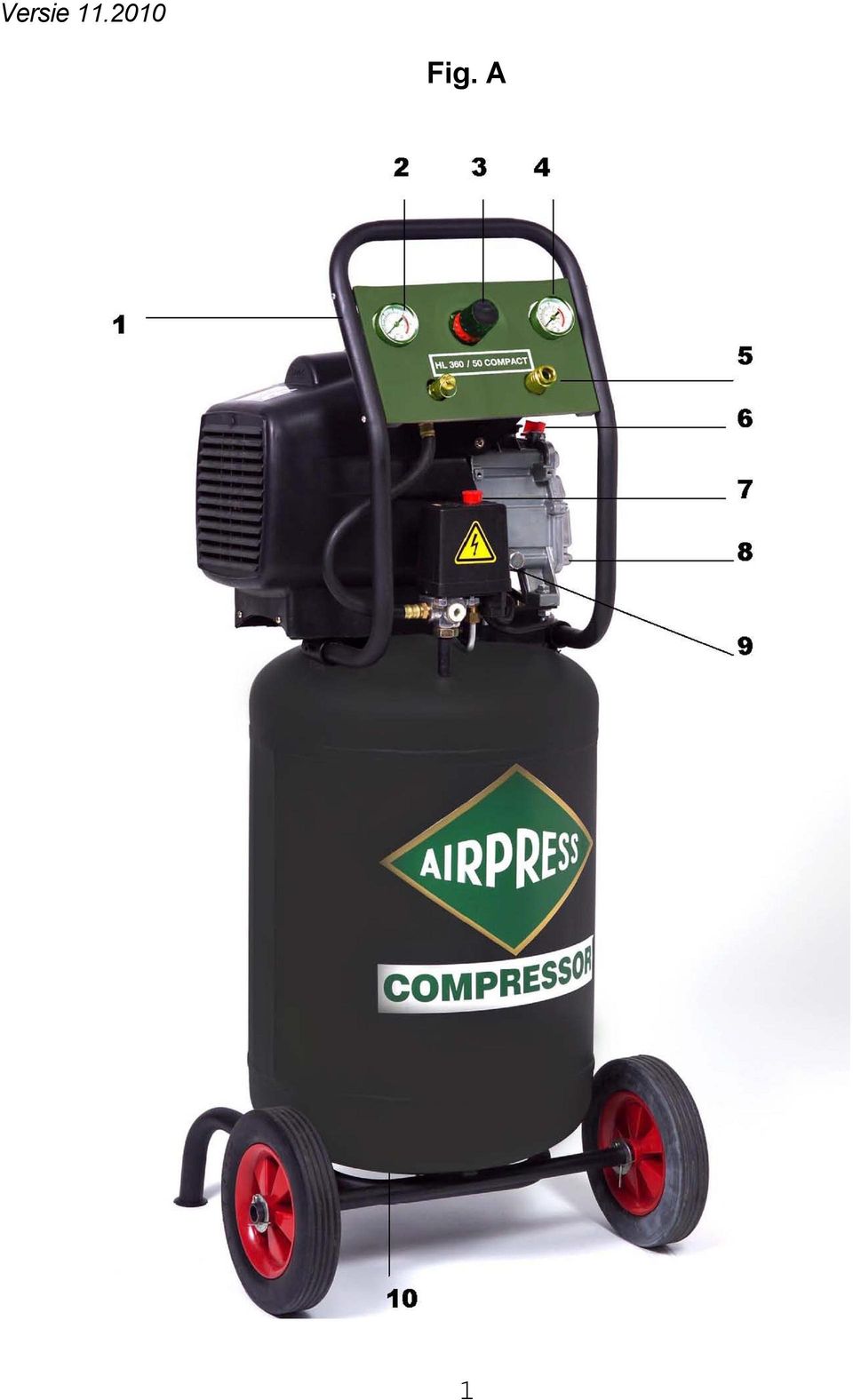
4 NEDERLANDS INHOUDSOPGAVE 1.0 Voorwoord pagina Veiligheidsvoorschriften pagina Opstelling pagina Elektrische aansluitingen pagina Luchtaansluitingen pagina Ingebruikname pagina Bediening pagina Onderhoud pagina Storingsmogelijkheden pagina Technische gegevens pagina 8 Onderdelentekening pagina 53 ATTENTIE Voordat de compressorinstallatie mag draaien, moet eerst een aantal noodzakelijke handelingen worden verricht. Lees daarom voor de ingebruikname eerst aandachtig deze handleiding door. 1.0 VOORWOORD Met de aankoop van uw Airpress compressorinstallatie bent u eigenaar geworden van een compressorinstallatie met een hoog prestatie- en betrouwbaarheidsniveau. Bij correct gebruik en goed onderhoud zal de machine dit vele jaren kunnen handhaven. In deze handleiding vindt u gebruiks- en onderhoudsvoorschriften. Lees het aandachtig door en bewaar het als vraagbaak bij uw compressor. De compressor is geschikt voor aanvoer van perslucht. De gecomprimeerde lucht is niet geschikt om in te ademen en mag niet in direkt contact komen met levensmiddelen. De machine mag alleen worden gebruikt voor het doel waarvoor hij is ontworpen en bedoeld; alle andere toepassingen zijn niet juist. De fabrikant is niet verantwoordelijk voor enige schade aan personen en zaken, veroorzaakt door onzorgvuldigheid of het niet opvolgen van de aangegeven voorschriften tijdens de werking van de machine of onderhoudswerkzaamheden. Deze machine is niet geschikt om buiten te worden opgesteld. Legenda (fig. A) 1 Luchtfilter 6 Olievulplug 2 Manometer 7 Drukschakelaar 3 Reduceerventiel 8 Oliepeilglas 4 Manometer 9 Olieaftapplug 5 Koppeling 10 Condenswateraftapkraan 2

5 2.0 VEILIGHEIDSVOORSCHRIFTEN Attentie: lees onderstaande veiligheidsvoorschriften voor ingebruikname aandachtig door. Let erop dat anderen, die de compressor gebruiken, deze handleiding aandachtig hebben doorgelezen en de nodige voorzorgsmaatregelen hebben genomen. Het apparaat mag alleen door volwassen personen worden bediend. Houd kinderen en bezoekers uit de buurt van de compressor tijdens gebruik. Wees voorzichtig bij het gebruik van perslucht. Richt de luchtstroom nooit op mensen of dieren. Gebruik de perslucht niet om kleding schoon te maken. Perslucht is niet geschikt om in te ademen. Draag geen wijde, loshangende kleding die in de bewegende delen vast kan komen te zitten. Draag tijdens gebruik bij voorkeur een veiligheidsbril, veiligheidsschoenen of schoenen met profielzolen en bedek lang haar met een haarnet om te voorkomen dat het haar in de machine vast komt te zitten. Gebruik de compressor uitsluitend in een droge, goed geventileerde omgeving en stel de machine niet bloot aan regen. Plaats de compressor op een voldoende draagkrachtige, vlakke vloer, zodat alle daartoe bestemde punten ook werkelijk dragen. Eventueel kan ter vermindering van trillingen, de machine op trillingdempers worden geplaatst. Deze compressor is niet geschikt voor continugebruik. De pomp moet tussendoor voldoende tijd krijgen om af te koelen. De machine heeft een inschakelduur van 30% per 60 minuten. Zorg voor een goede verlichting in de werkruimte. Gebruik het apparaat niet in een omgeving waar gas, benzine of andere ontvlambare stoffen aanwezig zijn. Overschrijd de maximum werkdruk niet en gebruik de machine uitsluitend bij een omgevingstemperatuur tussen +5ºC en +40ºC. Het is niet toegestaan om de beschermings- en veiligheidsinstrumenten te verwijderen of de instellingen te wijzigen. De werkende onderdelen van de machine kunnen tijdens gebruik heet worden. Laat de compressor na gebruik afkoelen. Na elk gebruik dient de tank te worden ontlucht en het condenswater dat zich in de tank heeft verzameld te worden afgetapt. Controleer of de elektrische installatie goed gezekerd is en of deze overeenkomt met het vermogen, het voltage en de frequentie van de motor. Controleer of de elektrische installatie geaard is en of er een aardlekschakelaar in de meterkast zit. Gebruik verlengkabels van voldoende capaciteit en vermijd het gebruik van onvoldoende geïsoleerde aansluitingen. Open nooit de schakelkast op de motor: alleen een erkende vakman mag deze openmaken. De machine en de kabel mogen nooit met water in contact komen. Wees voorzichtig met de stroomkabel. Trek niet aan de stroomkabel om de machine te verplaatsen of de stekker uit het stopcontact te halen. Houd de kabel uit de buurt van buitengewone hitte, olie en scherpe objecten. 3

6 Trek altijd de stekker uit het stopcontact indien: - u even weg moet - de machine niet wordt gebruikt - u onderhoudswerkzaamheden gaat uitvoeren - u hulpstukken gaat omwisselen - u de machine wilt verplaatsen Laat de compressor nooit onbeheerd lopen! WAARSCHUWING: de waarschuwingen, veiligheidsvoorschriften en aanwijzingen in deze handleiding kunnen niet alle mogelijke omstandigheden en situaties omvatten. De gebruiker dient te begrijpen dat gezond verstand en voorzichtigheid factoren zijn die niet in dit product kunnen worden ingebouwd, maar door de gebruiker zelf moeten worden ingevuld. Laat alleen personen die door het lezen van deze gebruiksaanwijzing op de hoogte zijn van het gebruik van deze machine, er gebruik van maken. Onoordeelkundig gebruik is gevaarlijk. Waarschuwingstekens (pagina 56) De stickers op de compressorunit maken deel uit van de machine; zij zijn aangebracht voor de veiligheid en mogen niet worden verwijderd of beschadigd. 3.0 OPSTELLING Plaats de compressor op een voldoende draagkrachtige, vlakke vloer, zodat alle daartoe bestemde punten ook werkelijk dragen. Eventueel kan ter vermindering van trillingen, de machine op trillingdempers worden geplaatst. De compressor dient in een goed geventileerde, zoveel mogelijk stofvrije ruimte te worden opgesteld. Plaats de machine nooit in een ruimte waar gespoten wordt. Goede ventilatie is nodig voor de afvoer van koellucht. Let erop dat de condenswateraftapkraan (10) en de olie-aftapplug (9) goed bereikbaar blijven, evenals de olievulplug (6). Aanbevolen wordt een ruimte van minimaal 30 centimeter rondom de machine vrij te laten voor ventilatie en onderhoudswerkzaamheden. In het algemeen geldt dat onvoldoende luchtaanvoer, een te hoge temperatuur en vervuiling van het luchtfilter het rendement van de compressor aanzienlijk verlagen. 3.1 ELEKTRISCHE AANSLUITINGEN In de fabriek is de machine al geheel van bedrading voorzien. De compressor moet echter nog aan uw elektrisch net worden aangesloten. Dit dient te geschieden op een aparte groep. Let erop dat het voltage en het ampèrage van uw elektrische installatie overeenkomt met dat van de motor. Ook de diameter van de gebruikte kabels is hierbij van belang. Aangeraden wordt kabels te gebruiken van tenminste 2,5 mm 2 en een lengte van maximaal 10 meter. N.B. Lees voor u de machine inschakelt eerst de hoofdstukken 3.2 en LUCHTAANSLUITINGEN Gebruik voor de aansluiting van de compressor op het luchtleidingnet een flexibele slang om trillingen van de machine te isoleren. 4

7 4.0 INGEBRUIKNAME 1. Controleer of rekening is gehouden met de onder "Opstelling" gegeven aanwijzingen. 2. De compressor is voor aflevering meestal gevuld met olie. Vul bij met ongeveer 0,8 liter compressorolie tot aan de rode cirkel op het oliepeilglas. 3. Monteer het luchtfilter in de cilinderkop (verwijder daarvoor eerst de kunststofplug). 4. Monteer de olievulplug (6) op het carterdeksel (verwijder daarvoor eerst de kunststofplug). 5. Vermijd verlengsnoeren. Is dit niet mogelijk, gebruik dan snoeren van voldoen-de capaciteit en rol ze geheel af. Tabel verlengsnoeren: 0-10 meter: 3 x 2,5 mm 2 Schakel met de handbediening van de drukschakelaar (7) de compressor in. De compressor zal nu gaan draaien, tenzij de ketel nog op druk staat (zie manometer nr. 2). Schakel de machine tijdens het draaien uitsluitend uit door de knop op de automatische drukschakelaar (7). Hierdoor wordt de persleiding ontlucht en kan de compressor weer onbelast aanlopen. 5.0 BEDIENING 1. De automatisch werkende compressor zal bij een keteldruk (2) van 8 bar stoppen. Wanneer weer lucht gebruikt wordt en de druk in de tank daalt tot 6 bar, zal de compressor opnieuw gaan draaien. 2. De meeste persluchtwerktuigen zijn berekend op een werkdruk van ongeveer 6 bar. Voor sommige toepassingen ligt deze druk nog lager. Om de juiste druk in te kunnen stellen is de compressor voorzien van een reduceerventiel (3). Dit ventiel kan de druk aan koppeling (5) instellen onafhankelijk van de keteldruk. 3. De instelling van het reduceerventiel gaat als volgt: draai de knop om de juiste druk in te stellen (linksom geeft een lagere druk, rechtsom een hogere). De ingestelde druk is af te lezen op manometer (4). 5

8 6.0 ONDERHOUD Voordat men met zijn werkzaamheden aan de machine mag beginnen, moet eerst de stroom worden uitgeschakeld (let erop dat deze niet per ongeluk weer kan worden ingeschakeld) en moet de ketel ontlucht worden d.m.v. het openen van de condenswateraftapkraan (10). Het onderhoud aan de machine betreft de volgende punten: 1. Na de eerste 50 bedrijfsuren en daarna iedere 250 bedrijfsuren dient de olie te worden afgetapt en ververst. Draai hiertoe de aftapplug (9) eruit en verwijder de vuldop (6). Vang de afgewerkte olie op. Als geen olie meer uitloopt, de aftapplug (9) weer indraaien en olie bijvullen. Het juiste oliepeil ligt op de rode cirkel op het oliepeilglas (8). Afgewerkte olie afvoeren volgens de voorschriften! 2. Tap regelmatig het condenswater af. Door afkoeling van warme lucht in de tank verzamelt zich daar condensvocht. Dit kan worden afgetapt met de aftapkraan (10) aan de onderzijde van de tank. Aftappen kan het beste onder druk geschieden. Het condensaat afvoeren volgens de voorschriften (dus niet in het riool!). U kunt ook een condensaatreiniger plaatsen. 3. Het oliepeil moet regelmatig worden gecontroleerd. Vul zonodig bij met compressorolie, bestelnr (0,6 l) of bestelnr (1 l). Dagelijkse controle kan veel narigheid voorkomen! Altijd dezelfde olie gebruiken als die in de machine zit; verschillende minerale oliën mogen beslist niet worden gemixt! 4. Regelmatig dient het luchtfilterelement (1) te worden schoongeblazen of vervangen. Verwijder daartoe het plastic filterhuis en neem het element uit. Stof kan met een blaaspistool uit het filter worden verwijderd. Hardnekkig vuil als bijvoorbeeld verfnevel noopt tot vervanging. De frequentie van schoonmaken is afhankelijk van de mate van vervuiling van de lucht in de werkomgeving van de compressor. Schone lucht is daarom erg belangrijk. N.B. Bedenk dat regelmatig onderhoud het rendement van uw machine ten goede komt en het behoud van uw machine is! ONDERHOUDSTABEL werkzaamheden dagelijks wekelijks iedere iedere condenswater aftappen oliepeil controleren luchtfilter reinigen olie verversen (1 e keer na 50 uur) uur 1000 uur
 weer indraaien en olie bijvullen. Het juiste oliepeil ligt op de rode cirkel op het oliepeilglas (8).")
9 7.0 STORINGSMOGELIJKHEDEN 1 Compressor doet niets bij inschakelen drukschakelaar: * netzekering defect - vernieuwen * tank is op druk - ontlasten * motor defect - repareren of vernieuwen * drukschakelaar defect - repareren of vernieuwen 2 Compressor valt steeds thermisch uit: * fase uitgevallen - netzekering vernieuwen * draad los - opsporen en verhelpen * drukschakelaar ontlast persleiding niet - afblaasventiel repareren/vervangen * onderspanning - verlengsnoeren verwijderen/ verzwaren * overbelasting - minder belasten 3 Compressor blijft afblazen: * terugslagklep defect - repareren of vernieuwen 4 Te weinig luchtopbrengst: * luchtfilter vervuild - reinigen of vernieuwen * kleppen defect - vernieuwen * wateraftapkraan staat open - dichtdraaien 5 Veiligheidsventiel lekt: * druk te hoog - drukschakelaar bijstellen * veiligheidsventiel defect - vernieuwen 8.0 TECHNISCHE GEGEVENS Type HL 360/50 compact Bestelnummer Aantal cilinders/trappen 1/1 Motorvermogen 2,5 pk/1,8 kw Voltage 230 V/50 Hz Inhoud persluchttank 50 liter Inhoud olietank 0,8 liter Inschakeldruk 6 bar Maximale druk 8 bar Geluidsniveau op 7 m 78 db(a) Aanzuigcapaciteit 360 l/min. Afzekeren met 16 amp. Inschakelduur 30% per 60 minuten Gewicht 38 kg Afmetingen (lxbxh) 480x410x1050 mm Modelwijzigingen voorbehouden. Alle compressoren zijn voorzien van Euro-Norm (CE-keur). 7

10 DEUTSCH INHALTSANGABE 1.0 Vorwort Seite Sicherheitsmaßnahmen Seite Aufstellung Seite Elektrischer Anschluß Seite Preßluft Anschluß Seite Erster Gebrauch Seite Bedienung Seite Wartung Seite Mögliche Störungen Seite Technische Daten Seite 13 Ersatzteile Seite 53 ACHTUNG Bevor der Kompressor funktionieren darf, müssen zuerst einige notwendige Maßnahmen beachtet werden. Lesen Sie diese Betriebsanleitung aufmerksam durch. 1.0 VORWORT Mit dem Kauf Ihres Airpress Kompressors sind Sie Besitzer eines Kompressors mit einer hohen Leistung und Zuverlässigkeit geworden. Bei einem korrekten Gebrauch und regelmäßiger Wartung wird die Maschine eine lange Lebensdauer haben. Diese Betriebsanleitung enthält Gebrauchs- und Wartungsvorschriften. Lesen Sie es aufmerksam durch und bewahren Sie es als eine Anleitung zu Ihrem Kompressor auf. Der Kompressor dient zur Erzeugung von Druckluft. Die vom Gerät erzeugte Luft darf weder eingeatmet werden, noch direkt in Kontakt mit Lebensmittel kommen. Dieses Gerät wurde für einen bestimmten Gebrauch konzipiert und darf deshalb nicht zweckentfremdet werden. Der Hersteller kann für eventuelle Schäden durch unsachgemäßen oder irrtümlichen Gebrauch nicht zur Haftung gezogen werden Das Gerät eignet sich nicht für die Aussen-Installation. Erklärung (Fig. A) 1 Luftfilter 6 Füllpfropfen 2 Manometer 7 Druckschalter 3 Reduzierventil 8 Ölschauglas 4 Manometer 9 Ölablaß 5 Kupplung 10 Kondenzwasserablaß 8

11 2.0 SICHERHEITSMASSNAHMEN Achtung: lesen Sie diese Sicherheitsmaßnahmen aufmerksam durch, bevor Sie die Maschine in Betrieb setzen. Achten Sie darauf daß andere Leute die mit dem Apparat arbeiten auch die Vorschriften gelesen und die notwendigen Maßnahmen getroffen haben. Das Apparat darf nur durch Erwachsenen bedient werden. Halten Sie Kinder und Besucher fern. Vorsicht beim Umgang mit Druckluft. Richten Sie den Luftstrom niemals auf Personen oder Tiere. Verwenden Sie keine Druckluft zur Reinigung von Kleidung. Druckluft is nicht zum Einatmen. Tragen Sie keine weiten, frei hängenden Kleider oder Schmuck; diese können sich in den bewegenden Teilen verhaken. Tragen Sie unbedingt eine Schutzbrille und rutschfeste Schuhe und bedecken Sie langes Haar mit einem Haarnetz. Verwenden Sie das Gerät nur im Freien und in trockener, gut belüfteter Umgebung und benutzen Sie den Kompressor nicht im Regen. Der Kompressor soll so aufgestellt werden, daß alle Punkte die dafür vorgesehen sind, tatsächlich auf dem Boden Stehen. Sorgen Sie für eine horizontale Aufstellung. Der Kompressor ist nicht geeignet für Dauerbetrieb, aber hat ein Aussetzbetrieb von 30% pro 60 Minuten. Sorgen Sie für eine gute Beleichtung in das Arbeitsraum. Die Maschine darf auf keinen Fall in explosions- oder brandgefährdeten Räumen bzw. an Arbeitsplätzen aufgestellt werden, wo gefährliche Stoffe wie z.b Gas, Benzin, entzündbare Dämpfe, Lösemittel usw. Entweichen. Überschreiten Sie niemals den maximalen Betriebsdruck und verwenden Sie das Gerät nur bei Umgebungstemperaturen zwischen +5ºC und +40ºC. Es ist nicht gestattet um die Schutz- und Sicherheitsinstrumente zu entfernen oder die Einstellungen zu ändern. Die arbeitenden Teile des Geräts können beim Betrieb heiß werden. Lassen Sie das Gerät nach dem Gebrauch abkühlen. Nach jedem Gebrauch muß der Tank belüftet und die im Tank gesammelte Feuchtigkeit abgelassen werden. Wird der Tank nicht entleert, so kann dies zu Leckbildung und dadurch gefährlichen Situationen führen. Beachten Sie daß die benötigte Spannung tatsächlich vorhanden ist. Anschluß soll nur an eine geerdete Steckdose erfolgen. Benutzen Sie nur Verlängerungskabel mit einem genügenden Durchmesser und vermeiden Sie die Verwendung von unzureichend isolierten Anschlüssen. Öffnen Sie nie der Schaltkasten auf dem Motor; nur ein anerkannter Fachman darf den Schaltkasten öffnen. Die Maschine und der Kabel darfen nie Kontakt machen mit Wasser. Ziehen Sie nicht am Stromkabel um die Maschine umzustellen oder den Stecker aus der Steckdose zu holen. Halten Sie den Kabel fern von außergewöhnlicher Hitze, Öl oder scharfen Objekten. Ziehen Sie immer den Stecker aus der Steckdose: 9

12 - bevor Sie weglaufen vom Apparat - wenn die Maschine nicht gebraucht wird - vor jedem Wartungseingriff - bevor Sie Zubehörteile wechseln - bevor Sie die Machine umstellen Lassen Sie den Kompressor nie unbeaufsichtigt drehen! WARNHINWEISE: die Warnhinweise und Sicherheitsvorschrifte sowie die Anweisungen, die in dieser Gebrauchsanweisung behandelt werden, können nicht alle möglichen Bedingungen und Situationen umfassen, die auftreten können. Der Bediener muss verstehen, dass gesunder Menschenverstand und Vorsicht Faktoren sind, welche nicht in das Produkt eingebaut werden können, aber vom Bediener selbst zur Verfügung gestellt werden müssen. Die Betriebsanleitung ist von jedem Benutzer vor dem ersten Gebrauch sorgfältig zu lesen. Unverständiger Gebrauch ist lebensgefährlich. Gefahrenschilder (Seite 56) Die Schilder die sich auf der Kompressor befinden, sind Teil der Maschine. Sie sind aus Sicherheitsgründen angebracht und dürfen auf keinen Fall entfernt oder beschädigt werden. 3.0 AUFSTELLUNG Der Kompressor soll so aufgestellt werden, daß alle Punkte die dafür vorgesehen sind, tatsächlich auf dem Boden Stehen. Sorgen Sie für eine horizontale Aufstellung. Der Motor soll genügend Kühlluft bekommen, also niemals die Ventilationsöffnungen abdecken. Den Kompressor in einen kühlen staubfreien Raum stellen wo nie gespritzt wird. Lacknebel verstopft nämlich den Luftfilter und schlägt auch auf den Kompressor nieder. Darauf achten, daß der Kondenzwasserablaß (10), der Öllablaß (9) und der Ölfüllpfropfen (6) immer zu erreichen sind. Darum empfehlen wir einen Raum von ca. 30 cm für Ventilation und Wartung zu lassen. Schützen Sie die Maschine für Frost und Regen. Bei Temperaturen unter 0 Grad Celsius können Ventile festfrieren und Beschädigungen an Pumpe und Motor entstehen. Bemerkung: ungenügende Luftzufuhr, zu hohe Temperaturen und Verschmutzung, verringern den Nutzeffekt. 3.1 ELEKTRISCHER ANSCHLUß Der Kompressor ist schon vom Hersteller verkabelt und funktionsfähig. Beachten Sie, daß die benötigte Spannung tatsächlich vorhanden ist. Anschluß soll nur an eine geerdete Steckdose erfolgen. Vermeiden Sie Verlängerungskabel. Soll das unvermeidlich sein, rollen Sie diese ganz ab. Benützen Sie nur kabel mit dem richtigen Durchmesser. Der Hersteller empfiehlt Kabel von mindestens 2.5 qmm und maximaler Länge von 10 Meter. Achtung: lesen Sie vor Gebrauch Kapitel 3.2 und PRESSLUFT ANSCHLUß Am besten benützen Sie zur Anschließung des Kompressors an ein Luftsystem einen flexiblen Schlauch. Hierdurch wird die Durchgabe der Fibrationen der Maschine an 10

13 dem Lufsystem vermeidet. 4.0 ERSTER GEBRAUCH 1. Kontrollieren Sie ob alle o.g. Punkte beachtet sind. 2. Der Kompressor ist für Ablieferung meistens mit Öl gefüllt. Nachfüllen mit etwa 0,8 Liter Kompressorenöl bis dem roten Kreis auf dem Ölschauglas. 3. Montieren Sie den Luftfilter (1) in den Zylinderkopf (dafür zuerst den Kunststoffpfropfen entfernen). 4. Montieren Sie den Füllpfropfen (6) auf den Kurbelgehäusedeckel (dafür zuerst den Kunststoffpfropfen entfernen). 5. Vermeiden Sie Verlängerungskabel. Soll das unvermeidlich sein, rollen Sie diese ganz aus. Tabelle für Verlängerungskabel: 0-10 Meter: 3 x 2,5 mm 2 Den Kompressor mit der Handbedienung des Druckschalters (7) einschalten. Der Kompressor arbeitet nun, es sei denn der Kessel hat noch genügend Druck (Manometer Nr. 2). Schalten Sie den Kompressor während des Gebrauches nur mit dem Knopf am automatischen Druckschalter (7) aus. Auf diese Weise wird die Preßluftleitung entlüftet und der Kompressor kann wieder unbelastet anlaufen. 5.0 BEDIENUNG 1. Der automatisch funktionierende Kompressor wird bei einem Kesseldruck (2) von 8 bar ausschalten. Wenn wieder Pressluft verbraucht wird und der Druck im Tank fällt ab auf 6 bar, wird der Kompressor wieder einschalten. 2. Die meisten Pressluftgeräte arbeiten mit einem Arbeitsdruck von ca. 6 bar. Für einige Anwendungen liegt dieser Druck noch niedriger. Um den richtigen Druck einzustellen, ist der Kompressor mit einem Reduzierventil (3) versehen. Mit diesem Ventil kann der Druck an der Kupplung (5) eingestellt werden, unabhängich vom Druck im Kessel. 3. Die Einstellung des Reduzierventils geschieht wie folgt: drehe den Knopf zum Einstellen des gewünschten Drucks (nach links für ein niedrigeren Druck, nach rechts für ein höheren Druck.) Sie können den eingestellten Druck ablesen auf dem Manometer (4). 11
 einschalten.")
14 6.0 WARTUNG Vor jedem Wartungseingriff muß die Maschine angehalten und spannungslos gesetzt werden und muß der Tankdruck abgelassen werden mittels den Kondenswasserablaß (10) zu öffnen. 1. Das erste Mal soll das Öl schon nach etwa 50 Arbeitsstunden gewechselt werden und danch alle 250 Arbeitsstunden. Dazu Ölablaß (9) abdrehen und Füllpfropfen (6) entfernen. Das Altöl auffangen. Wenn kein Öl mehr ausläuft, Ölablaß (9) wieder eindrehen und Öl einfüllen. Der richtige Ölspiegel liegt auf den roten Kreis auf das Ölschauglas (8). Bitte halten Sie sich an die einschlägigen Bestimmungen für die Entsorgung von Altöl! 2. Regelmäßig Kondenswasser ablassen. Der Ablaß (10) befindet sich an der unteren Seite des Kessels. Ablaß mit noch ein wenig Druck im Kessel geht am Besten. Das abgelassene Kondenswasser muß vorschriftsmäßig entsorgt werden (nicht im Abzugskanal!). Auch können Sie einen Kondensatreiniger montieren. 3. Der Ölstand soll regelmäßig kontrolliert werden. Wenn nötig nachfüllen mit Kompressorenöl, Bestellnr (0,6 l) oder Bestellnr (1 l). Am besten kontrollieren Sie den Ölstand jeden Tag. Es muß unbedingt die gleiche Ölsorte verwendet werden, die sich in der Maschine befindet. Das Öl darf nicht mit anderen Sorten vermischt werden. 4. Der Luftfilter (1) soll auch regelmäßig erneuert werden. Die Erneuerung ist abhängig von der Verschmutzung und soll dementsprechend erfolgen. Zur Reinigung des Luftfilters, Filterkappe mit Filter abdrehen. So können Sie den Filter mit Druckluft ausblasen. Achtung: Regelmäßige Wartung verlängert die Leistung und Lebensdauer. WARTUNGSTABELLE Arbeiten Täglich Wöchent- Alle 250 Alle 1000 lich lich Stunden Stunden Kondenswasser ablassen Ölstand kontrollieren Luftfilter reinigen Öl erneuern (1 e Mal nach 50 Arbeitsstunden) 12
 befindet sich an der unteren Seite des Kessels.")
15 7.0 MÖGLICHE STÖRUNGEN 1 Kompressor läuft nicht beim Einschalten: * defekte Sicherung - erneuern * Draht los - reparieren * Tank auf Druck - Luft entnehmen * defekter Motor - reparieren/erneuern * defekter Druckschalter - reparieren/erneuern 2 Kompressor fällt ständig thermisch aus: * Druckschalter entlüftet nicht - Ablaßventil erneuern/reparieren * Unterspannung - Verlängerungskabel entfernen * Phase ausgefallen - Sicherung erneuern * Draht los - reparieren * Überlastung - Belastung reduzieren 3 Luft bläst ständig ab: * Rückschlagventil defekt - reparieren/erneuern 4 Zu wenig Kapazität: * Luftfilter verschmutzt - reinigen/erneuern * Ventile defekt - erneuern * Kondenzwasserablaßhahn ist offen - zudrehen 5 Sicherheitsventil ist undicht: * Druck zu hoch - Druckschalter nachstellen * defektes Sicherheitsventil - erneuern 8.0 TECHNISCHE DATEN Typ HL 360/50 compact Bestellnummer Zylinderzahl/Stufenzahl 1/1 Motorleistung 2,5 Ps/1,8 kw Spannung 230 V/50 Hz Inhalt Preßluftbehälter 50 Liter Inhalt Ölbehälter 0,8 Liter Arbeitsdruck 6 Bar Maximaler Druck 8 Bar Schallpegel 78 db(a)/7 m Ansaugleistung 360 L/Min. Sichern mit 16 Amp. Aussetzbetrieb 30% pro 60 Minuten Gewicht 38 Kg Abmessung (LxBxH) 480x410x1050 mm Modelländerungen vorbehalten. Alle Kompressoren sind mit Euro-Norm (CE-Wahl) versehen 13

16 ENGLISH TABLE OF CONTENTS 1.0 Prefatory note page Safety instructions page Placing page Electric connection page Air connection page First use page Operation page Maintenance page Possibilities of failure page Technical details page 19 Spare parts page 53 ATTENTION To be able to use this compressor installation properly, a number of measurements must be taken. The following points will contribute to making you a satisfied user of this installation. 1.0 PREFATORY NOTES Buying your Airpress compressor installation, you have become the owner of a compressor installation with a high performance and reliability level. Correct use and regular maintenance will increase the life of the compressor. In this manual you will find operation and maintenance instructions. Read it carefully and keep it as a guide to your compressor. The compressor has been built to supply compressed air. In particular the appliance cannot be used to produce air to be breathed by humans or used on direct contact with foodstuffs. The appliance must be used only for the purpose for which it was specifically designed. All other uses are to be considered incorrect and therefore unreasonable. The manufacturer cannot be held responsible for any damage resulting from improper, incorrect or unreasonable use. This machine is not suitable for external installation. Legend (fig. A) 1 Air filter 6 Oil filler cap 2 Pressure gauge 7 Pressure switch 3 Reducing valve 8 Oil leveler 4 Pressure gauge 9 Oil drain plug 5 Coupling 10 Draintap for condensation water 14

17 2.0 SAFETY INSTRUCTIONS Important: please read and observe the following safety instructions before using the machine. Nobody must be allowed to use the compressor unless they have read the instruction manual and have been instructed in the regulations to follow for correct and safe use. The machine must be used by adults only. Use of the compressor by apprentices of not less than 16 years of age must be supervised by an adult authorised to use the machine. Keep children and visitors away from the working area. Be cautious when using compressed air. Never aim the air flow at people or animals. Do not use compressed air to clean clothing. Compressed air is not suitable to inhale. Do not wear loose clothing or neckties that can get caught in moving parts. Preferably wear safety goggles, nonslip footwear and Wear protective hair covering to contain long hair. Only use the machine outside in dry, well-ventilated surroundings and do not expose the machine to rain. The compressor should be placed in such way that all points, destined to carry it will really do so. Take also care of a horizontal position. This machine is not fit for continuous running, but service for 30% per 60 minutes. Keep your work area clean and well lighted. Do not use the machine in areas where fumes from paint, solvents or flammable liquids pose a potential hazard. Do not exceed the maximum operating pressure and only use the machine in an ambient temperature between +5ºC and +40ºC. Never attempt to tamper with the protections of the log splitter or to operate the machine without these. The working parts of the machine can become hot during operation. Let the machine cool down after use. After each use the tank must be vented and the moisture collected in the tank must be bled. Not bleeding the tank can lead to leakage and may cause a dangerous situation. Check that the electric circuit is adequately protected and that it corresponds with the power, voltage and frequency of the motor. Check that there is a ground connection and a regulation differential switch upstream. Use cables with an adequate section and avoid use of free and inadequately insulated connections. Never open the pushbutton box on the motor. Should this be necessary, contact a qualified electrician. Make sure that the machine and the cable never come in contact with water. Treat the power cable with care. Do not attempt to move the machine by pulling the cable. Do not yank the cable to unplug it; keep the cable away from excessive heat, oil and sharp objects. 15

18 Never leave the machine unattended with the power supply "on". Also disconnect the power cable when: - you leave the machine, even for a short time - not in use - carrying out maintenance work - changing attachment or moving the machine. WARNING: the warnings, cautions and instructions discussed in this instruction manual cannot cover all possible conditions and situations that may occur. It must be understood by the operator that common sense and caution are factors which cannot be built into this product, but must be supplied by the operator. Only those persons who are aware of how to use the compressor by having read this manual, should use the machine. Injudicious use may cause danger. Danger plates (page 56) The plates fitted on the compressor unit are part of the machine; they have been applied for safety purposes and must not be removed or spoiled for any reason. 3.0 PLACING The compressor should be placed in such way that all points, destined to carry it will really do so. Take also care of a horizontal position. The engine should get sufficient cooling air; so never cover the ventilating openings. Place the compressor in a cool dustfree space. Never place the compressor in a room where will be sprayed. Paint spray will clog the air filter and will also deposit on the compressor. Mind that the draintap for condensation water (10), the oil drain plug (9) and the oil plug (6) will always remain attainable. We suggest to leave a space of aproximately 30 cm for ventilation and maintenance. Notice: Insufficient air supply, too high temperature and fouling of the air filter reduce the efficiency of the compressor considerably. 3.1 ELECTRIC CONNECTION At the factory the machine is already fully equipped with cables. The machine now has to be connected to your own electricity supply. Connect the machine to a separate group. Beware that voltage and amperage of your electric circuit meet the needs of the motor. Use only cables with the right diameter. The factory suggests to use cables of at least 2.5 qmm and a maximum length of 10 meter. Before first use first read chapters 3.2 and AIR CONNECTION Best use for connection of the compressor to an air circuit a flexible hose, to isolate fibrations from the machine. 16

19 4.0 FIRST USE 1. Check if the instructions mentioned above have been executed. 2. On delivery the compressor mostly is filled with oil. Fill about 0,8 litres compressor oil until the red circle on the oil leveler. 3. Install the air filter (1) in the cylinder head (first remove the synthetic plug). 4. Install the oil filler cap (6) on the crank case lid (first remove the synthetic plug). 5. Avoid the use of extension cables. If you use them, unroll them completely and use cables of sufficient capacity. Table for extension cables: 0-10 meter: 3 x 2,5 mm 2 Switch on the compressor by means of the pressure switch (7). The compressor will now operate, unless the air receiver is still under pressure (pressure gauge 2). Switch the machine, during operation, exclusively off by means of the button on the automatic pressure switch (7); the pressure circuit will be vented and the compressor can start again uncharged. 5.0 OPERATION 1. The automatically operating compressor will stop at a pressure of 8 bar. When air is used again and the pressure in the tank falls to 6 bar, the compressor will start again. 2. Most pneumatic machines are suitable for an operating pressure of about 6 bar. For some applications this pressure is even lower. To be able to set the right pressure, the compressor is provided with a reducing valve (3). This valve can set the pressure of the air receiver (of course never higher than the pressure in the air receiver). 3. The setting of the reducing valve is done as follows: switch the button to set the right pressure (to the left to lower the pressure, to the right to increase it). The set pressure can be read on the pressure gauge (4). 17
.")
20 6.0 MAINTENANCE Before carrying out any maintenance jobs it is obligatory to stop the machine, disconnect it from the power mains and make sure that the tank is pressure free by opening the condensation draintap (10). 1. After the first 50 operating hours and then every 250 operation hours the oil should be refreshed. Turn off the oil drain plug (90) and also remove the filler cap (6). Collect the oil. If the oil does not come out any longer, switch on the drainplug again and refill the oil (through fillercap) until the oil has reached the correct level. The right oil level is on the red circle on the oil leveler (8). Always respect the regulations in force for disposing of old oil! 2. Regularly drain condensation water. The draintap is situated at the bottom of the tank (10). Draining with pressure in the tank is the easiest way. Some compressors have an aftercooler with its own drainplug. Also from this device the condensationwater should be drained regularly. Condensate must be disposed of in conformity with the local regulations in force (not in the sewer!). As an alternative you can place an oil/water separator. 3. The oil level should also be checked regularly. For the right oil level see point 1. If necessary refill with compressor oil, order No (0,6 l) or order No (1 l). Checking daily can prevent a lot of troubles! Use oil of the same type as that already in the machine; do not mix different types of oil! 4. The air filter element (3) should be cleaned or changed regularly. This change depends on the amount of fouling and should be done more often in dusty situations and less often in a clean situation. For cleaning the filterelement, take out the filtercontainer with the filter. Then clean the filter by blowing off the dust. Note: Regular maintenance of your compressor will increase durability and reliability. MAINTENANCE TABLE works daily weekly every every draining condensation water check oil level clean air filter refresh oil (first time after 50 hours) 250 hours 1000 hours 18
. Always respect the regulations in force for disposing of old oil! 2. Regularly drain condensation water.")
HL 340/90 36844/E COMPRESSOR KOMPRESSOR COMPRESSOR COMPRESSEUR SPRĘŻARKA
 COMPRESSOR KOMPRESSOR COMPRESSOR COMPRESSEUR SPRĘŻARKA HL 340/90 36844/E Handleiding Gebrauchsanleitung Instruction manual Manuel d instructions Instrukcja obsługi - Przekład instrukcji oryginalnej Versie
Instrukcja Montażu. Zawór pilotowy. Zawór przełączający 3-drogowy. Zawór odcinający. Wkład filtrujący. Zawór iglicowy EB-FD300=A
 FD 300 Einbau-Anleitung Installation Instructions Instrukcja Montażu E1 Bauteile Components Części =Pilotventil Pilot valve Zawór pilotowy =3-Wege-Umschaltventil 3-Way manual selector Zawór przełączający
Manual Call Point FMC-210-DM-G-B FMC-210-DM-H-B FMC-210-DM-G-Y FMC-210-DM-G-GR. Installation Guide. deutsch english nederlands polski
 Manual Call Point FMC-20-DM-G-B FMC-20-DM-H-B FMC-20-DM-G-Y FMC-20-DM-G-GR Installation Guide deutsch english nederlands polski 06 0786 Bosch Sicherheitssysteme GmbH Robert-Bosch-Platz, D-70839 Gerlingen
Gruntowa Pompa Ciepła Bezpośredniego Odparowania DXW
 Gruntowa Pompa Ciepła Bezpośredniego Odparowania DXW Direct Expansion Earth Coupled Heat Pump DXW Pompe a Chaleur Geotermique a Evaporation Directe DXW MODEL ZH3 DXW65 Wydajność grzewcza Pobór mocy elektrycznej
HAPPY ANIMALS L01 HAPPY ANIMALS L03 HAPPY ANIMALS L05 HAPPY ANIMALS L07
 HAPPY ANIMALS L0 HAPPY ANIMALS L0 HAPPY ANIMALS L0 HAPPY ANIMALS L07 INSTRUKCJA MONTAŻU ASSEMBLY INSTRUCTIONS Akcesoria / Fittings K ZW W8 W7 Ø x 6 szt. / pcs Ø7 x 70 Narzędzia / Tools DO MONTAŻU POTRZEBNE
HAPPY ANIMALS L02 HAPPY ANIMALS L04 HAPPY ANIMALS L06 HAPPY ANIMALS L08
 HAPPY ANIMALS L02 HAPPY ANIMALS L04 HAPPY ANIMALS L06 HAPPY ANIMALS L08 INSTRUKCJA MONTAŻU ASSEMBLY INSTRUCTIONS Akcesoria / Fittings K O G ZW W8 W4 20 szt. / pcs 4 szt. / pcs 4 szt. / pcs 4 szt. / pcs
BLACKLIGHT SPOT 400W F
 BLACKLIGHT SPOT 400W F2000339 USER MANUAL / INSTRUKCJA OBSŁUGI BLACKLIGHT SPOT 400W F2000339 Table of Contents 1 Introduction... 2 2 Safety information... 2 3 Product information... 2 3.1 Specification...
WYŁĄCZNIK CZASOWY OUTDOOR TIMER
 003-582 PL WYŁĄCZNIK CZASOWY Instrukcja obsługi (Tłumaczenie oryginalnej instrukcji) Ważny! Przed użyciem uważnie przeczytaj instrukcję obsługi! Zachowaj ją na przyszłość. EN OUTDOOR TIMER Operating instructions
INSTRUCTION MANUAL. Strona 1
 INSTRUCTION MANUAL www.flash-butrym.pl Strona 1 LED SPOT LIGHT INSTRUCTION MANUAL Thank you for purchasing the LEDSPOT10W Spot light. It is a small and easy to carry unit that is simple to install. Features:
LED WASHER 30x3W WHITE IP65 F
 USER MANUAL / INSTRUKCJA OBSŁUGI LED WASHER 30x3W WHITE IP65 F7200171 LED WASHER 30x3W WHITE IP65 F7200171 Table of contents 1 Introduction... 2 2 Safety information... 2 3 Product information... 2 3.1
Instrukcja obsługi. ibind A8/A12/A15/A20. instruction manual. 80-393 GDAŃSK ul. Krynicka 1 tel.: (058) 55 43 555 fax: (058) 55 43 500
 55 43 555 fax: (058) 55 43 500") Instrukcja obsługi instruction manual 80-9 GDAŃSK ul. Krynicka tel.: (08) fax: (08) 00 ODDZIAŁ: 0-78 WARSZAWA ul. Janowskiego 9 tel.: (0) 8 0 8..9 fax: (0) 8 0 0 BindownicE ibind A8/A/A/A0 BINDING MACHINEs
Instrukcja obsługi instruction manual 80-9 GDAŃSK ul. Krynicka tel.: (08) fax: (08) 00 ODDZIAŁ: 0-78 WARSZAWA ul. Janowskiego 9 tel.: (0) 8 0 8..9 fax: (0) 8 0 0 BindownicE ibind A8/A/A/A0 BINDING MACHINEs
SSW1.1, HFW Fry #20, Zeno #25 Benchmark: Qtr.1. Fry #65, Zeno #67. like
 SSW1.1, HFW Fry #20, Zeno #25 Benchmark: Qtr.1 I SSW1.1, HFW Fry #65, Zeno #67 Benchmark: Qtr.1 like SSW1.2, HFW Fry #47, Zeno #59 Benchmark: Qtr.1 do SSW1.2, HFW Fry #5, Zeno #4 Benchmark: Qtr.1 to SSW1.2,
DO MONTAŻU POTRZEBNE SĄ DWIE OSOBY! INSTALLATION REQUIRES TWO PEOPLE!
 1 HAPPY ANIMALS B09 INSTRUKCJA MONTAŻU ASSEMBLY INSTRUCTIONS Akcesoria / Fittings K1 M M1 ZM1 Z T G1 17 szt. / pcs 13 szt. / pcs B1 13 szt. / pcs W4 13 szt. / pcs W6 14 szt. / pcs U1 1 szt. / pcs U N1
[ROBOKIDS MANUAL] ROBOROBO
![[ROBOKIDS MANUAL] ROBOROBO](/thumbs/24/4313056.jpg "[ROBOKIDS MANUAL] ROBOROBO") 1 2 When you plug in or unplug the cable, be sure to insert pressing the hook of the connection cable. If you want to input the program to your robot, you should first connect the Card reader with the
1 2 When you plug in or unplug the cable, be sure to insert pressing the hook of the connection cable. If you want to input the program to your robot, you should first connect the Card reader with the
Instrukcja obsługi. binding machine KRIS. instruction manual. 80-393 GDAŃSK ul. Krynicka 1 tel.: (058) 55 43 555 fax: (058) 55 43 500 ODDZIAŁ:
 55 43 555 fax: (058) 55 43 500 ODDZIAŁ:") Instrukcja obsługi instruction manual 80-393 GDAŃSK ul. Krynicka 1 tel.: (058) 55 43 555 fax: (058) 55 43 500 ODDZIAŁ: 02-784 WARSZAWA ul. Janowskiego 9 tel.: (022) 648 03 48..49 fax: (022) 648 03 50 bindownica
Instrukcja obsługi instruction manual 80-393 GDAŃSK ul. Krynicka 1 tel.: (058) 55 43 555 fax: (058) 55 43 500 ODDZIAŁ: 02-784 WARSZAWA ul. Janowskiego 9 tel.: (022) 648 03 48..49 fax: (022) 648 03 50 bindownica
NEDERLANDS... 2 DEUTSCH... 9 ENGLISH FRANÇAIS ESPAÑOL POLSKI Lees deze handleiding voor ingebruikname aandachtig door.
 COMPRESSOR KOMPRESSOR COMPRESSOR COMPRESSEUR KOMPRESOR HL 275/25 HL 275/50 36840-36845 Handleiding Vertaling van originele gebruiksaanwijzing Gebrauchsanleitung Übersetzung Original Instruction manual
SPINNER High reliability RF Power Loads
 D 5 W, 10 W OADS VSWR 0 f 1 GHz 1 f 2 GHz 2 f 5 GHz 5 f 7 GHz Effektive eistung BN 53 17 27 BN 53 17 12 BN 53 12 21 BN 53 12 25 0 f 7 GHz 1.06 1.11 1.17 1.22 5 W 2. 10 W 2. 1000 V N Stecker N male 7-16
LED PAR 56 7*10W RGBW 4in1 SLIM
 LED PAR 56 7*10W RGBW 4in1 SLIM USER MANUAL Attention: www.flash-butrym.pl Strona 1 1. Please read this specification carefully before installment and operation. 2. Please do not transmit this specification
Installation of EuroCert software for qualified electronic signature
 Installation of EuroCert software for qualified electronic signature for Microsoft Windows systems Warsaw 28.08.2019 Content 1. Downloading and running the software for the e-signature... 3 a) Installer
 www.irs.gov/form990. If "Yes," complete Schedule A Schedule B, Schedule of Contributors If "Yes," complete Schedule C, Part I If "Yes," complete Schedule C, Part II If "Yes," complete Schedule C, Part
Gruntowa Pompa Ciepła Bezpośredniego Odparowania DXW
 Gruntowa Pompa Ciepła Bezpośredniego Odparowania DXW Direct Expansion Earth Coupled Heat Pump DXW Pompe a Chaleur Geotermique a Evaporation Directe DXW ZH3 DXW65 W35 W45 W55 W65 E4 20,67 kw 3,93 kw COP
Stargard Szczecinski i okolice (Polish Edition)
") Stargard Szczecinski i okolice (Polish Edition) Janusz Leszek Jurkiewicz Click here if your download doesn"t start automatically Stargard Szczecinski i okolice (Polish Edition) Janusz Leszek Jurkiewicz
Stargard Szczecinski i okolice (Polish Edition) Janusz Leszek Jurkiewicz Click here if your download doesn"t start automatically Stargard Szczecinski i okolice (Polish Edition) Janusz Leszek Jurkiewicz
DM-ML, DM-FL. Auxiliary Equipment and Accessories. Damper Drives. Dimensions. Descritpion
 DM-ML, DM-FL Descritpion DM-ML and DM-FL actuators are designed for driving round dampers and square multi-blade dampers. Example identification Product code: DM-FL-5-2 voltage Dimensions DM-ML-6 DM-ML-8
Tychy, plan miasta: Skala 1: (Polish Edition)
") Tychy, plan miasta: Skala 1:20 000 (Polish Edition) Poland) Przedsiebiorstwo Geodezyjno-Kartograficzne (Katowice Click here if your download doesn"t start automatically Tychy, plan miasta: Skala 1:20 000
Tychy, plan miasta: Skala 1:20 000 (Polish Edition) Poland) Przedsiebiorstwo Geodezyjno-Kartograficzne (Katowice Click here if your download doesn"t start automatically Tychy, plan miasta: Skala 1:20 000
Zakopane, plan miasta: Skala ok. 1: = City map (Polish Edition)
") Zakopane, plan miasta: Skala ok. 1:15 000 = City map (Polish Edition) Click here if your download doesn"t start automatically Zakopane, plan miasta: Skala ok. 1:15 000 = City map (Polish Edition) Zakopane,
Zakopane, plan miasta: Skala ok. 1:15 000 = City map (Polish Edition) Click here if your download doesn"t start automatically Zakopane, plan miasta: Skala ok. 1:15 000 = City map (Polish Edition) Zakopane,
Instrukcja Montażu. Zawór elektromagnetyczny. Zawór kontrolny. Zawór odcinający. Krańcówka. Wkład filtracyjny EB-PS300=A
 PS300 Einbau-Anleitung Installation Instructions Instrukcja Montażu E1 Bauteile Components Części =Magnetventil Solenoid valve Zawór elektromagnetyczny =Regulierventil Check valve Zawór kontrolny ƒ=absperr-kugelhahn
099 Łóżko półpiętrowe 2080x1010(1109)x Bunk bed 2080x1010(1109)x1600 W15 INSTRUKCJA MONTAŻU ASSEMBLY INSTRUCTION
x Bunk bed 2080x1010(1109)x1600 W15 INSTRUKCJA MONTAŻU ASSEMBLY INSTRUCTION") INSTRUKCJA MONTAŻU ASSEMBLY INSTRUCTION 2 WAŻNE, ZACHOWAĆ DO PÓŹNIEJSZEGO STOSOWANIA- UWAŻNIE PRZECZYTAĆ IMPORTANT, SAVE FOR FURTHER USAGE- READ CAREFULLY INSTRUKCJA UZYTKOWANIA USER S MANUAL. Aby uniknąć
INSTRUKCJA MONTAŻU ASSEMBLY INSTRUCTION 2 WAŻNE, ZACHOWAĆ DO PÓŹNIEJSZEGO STOSOWANIA- UWAŻNIE PRZECZYTAĆ IMPORTANT, SAVE FOR FURTHER USAGE- READ CAREFULLY INSTRUKCJA UZYTKOWANIA USER S MANUAL. Aby uniknąć
F 18 GARANTIE. Notice d utilisation et d installation
 Notice d utilisation et d installation GARANTIE Installation and operating manual/ Gebruiks en installatiehandleiding / Manual de utilización e instalación / Manual do Utilizador e de Instalação /. Instrukcja
DO MONTAŻU POTRZEBNE SĄ DWIE OSOBY! INSTALLATION REQUIRES TWO PEOPLE!
 HAPPY ANIMALS RW08 INSTRUKCJA MONTAŻU ASSEMBLY INSTRUCTIONS Akcesoria / Fittings K M M ZM ZW G 0 szt. / pcs W szt. / pcs B szt. / pcs szt. / pcs W U 8 szt. / pcs 4 szt. / pcs U N szt. / pcs Ø3 x szt. /
Szklana półka scienna.
 Szklana półka scienna. PL - Instrukcja Obsługi or brick wall. Este producto ha sido diseñado para su uso en una pared vertical interpretarse de albañilería (cemento sólido) o vigas de madera o pared de
DO MONTAŻU POTRZEBNE SĄ DWIE OSOBY! INSTALLATION REQUIRES TWO PEOPLE!
 1 HAPPY ANIMALS SZ11 A INSTRUKCJA MONTAŻU ASSEMBLY INSTRUCTIONS Akcesoria / Fittings K1 M M1 ZM1 Z G1 szt. / pcs 0 szt. / pcs B1 6 szt. / pcs 6 szt. / pcs W6 0 szt. / pcs U1 19 szt. / pcs U 50 szt. / pcs
Installez un certificat ssl par l'intermédiaire du CLI sur un ESA
 Installez un certificat ssl par l'intermédiaire du CLI sur un ESA Contenu Introduction Prerequistes Installez un certificat ssl Informations connexes Introduction Ce document décrit comment installer un
 www.irs.gov/form990. If "Yes," complete Schedule A Schedule B, Schedule of Contributors If "Yes," complete Schedule C, Part I If "Yes," complete Schedule C, Part II If "Yes," complete Schedule C, Part
Jazz EB207S is a slim, compact and outstanding looking SATA to USB 2.0 HDD enclosure. The case is
 1. Introduction Jazz EB207S is a slim, compact and outstanding looking SATA to USB 2.0 HDD enclosure. The case is made of aluminum and steel mesh as one of the coolest enclosures available. It s also small
Bodentreppe Designo Seite 1 von 12
 Einbauanleitung / Bedienungsanleitung EN Installation manual FR Instructions de montage PL Instrukcja montazu EN Operating instructions FR Mode d emploi PL instrukcja obsługi Bodentreppe Designo DE Hinweise/Sicherheitshinweise
Zasady bezpieczeństwa
 2 3 Zasady bezpieczeństwa GB The door and the feeding flap must be closed when operating the machine! PL Drzwiczki i klapka szczeliny podawczej muszą być zamknięte w trakcie używania urządzenia! GB Ensure
FOG MACHINES User manual. FLM-600 Maszyna do dymu Instrukcja obsługi
 FLM-600 FOG MACHINES User manual FLM-600 Maszyna do dymu Instrukcja obsługi The guarantee for appropriate operation of the smoke machines is the using of the Flash-Butrym smoke liquid. www.flash-butrym.pl
PRZEKRÓJ A-A. The clearance specified in appendix VII, diagram 25a/b of Regulation No UN EU must be guaranteed at laden weight of the vehicle.
 PRZEKRÓJ - 75 min. 75 min. 30 o max. R 14,5 max. R40 max. 140 min. 55 min. 100 max. 32 min. 30 o max. 350-420 PL Należy zagwarantować przestrzeń swobodną według załącznika VII, rysunek 25a/b Regulaminu
HAPPY K04 INSTRUKCJA MONTAŻU ASSEMBLY INSTRUCTIONS DO MONTAŻU POTRZEBNE SĄ DWIE OSOBY! INSTALLATION REQUIRES TWO PEOPLE! W5 W6 G1 T2 U1 U2 TZ1
 HAPPY K0 INSTRUKCJA MONTAŻU ASSEMBLY INSTRUCTIONS W Akcesoria / Fittings W W G K szt. / pcs M Ø Ø 0 Ø, Ø Ø. 0 ø8 M 8 szt. / pcs 0 szt. / pcs szt. / pcs T U U szt. / pcs szt. / pcs szt. / pcs S TZ szt.
KWS. Instrukcja obsługi User's manual Manuel d utilisation Руководство по эксплуатации RMSI25, RMSI63
 1 Instrukcja obsługi User's manual Manuel d utilisation Руководство по эксплуатации RMSI25, RMSI63 Uwaga! Niebezpieczne napięcie może spowodować porażenie lub pożar. W związku z prowadzoną polityką ciągłego
A500Flash. Skrócona instrukcja instalacji... 2 Quick Guide... 5 A500Flash Kurzanleitung... 8
 A500Flash Skrócona instrukcja instalacji... 2 Quick Guide... 5 A500Flash Kurzanleitung... 8 1 Skrócona instrukcja instalacji Proces podłączenia adaptera dokonujemy zawsze przy wyłączonym zasilaniu Amigi.
Wyroby medyczne Systemy zarządzania jakością Wymagania do celów przepisów prawnych
 POPRAWKA do POLSKIEJ NORMY ICS 03.120.10; 11.040.01 PN-EN ISO 13485:2012/AC Wprowadza EN ISO 13485:2012/AC:2012, IDT Wyroby medyczne Systemy zarządzania jakością Wymagania do celów przepisów prawnych Poprawka
DTG 130 Eco.NOx DTG 1300 Eco.NOx V. Chaudières à gaz. Adaptation à un autre gaz. Français 07/03/11. 1 Collage de l'étiquette
 DTG 130 Eco.NOx DTG 1300 Eco.NOx V Chaudières à gaz Deutsch Polski 07/03/11 Adaptation à un autre gaz Les opérations décrites ci-après doivent être effectuées par un professionnel qualifié. Après avoir
11/ RENAULT MEGANE II 3/5 d. R/030. Cat. No. e20. e20*94/20*0375*00 D = 7,56kN. 1350Kg 75Kg. D (kn) = x 0, MAX kg.
 = x 0, MAX kg.") RENULT MEGNE II 3/5 d. 11/2002 - Cat. No. R/030 e20 e20*94/20*0375*00 1350Kg 75Kg D = 7,56kN D (kn) = MX kg x MX kg x 0,00981 MX kg + MX kg PRZEKRÓJ - 75 min. 75 min. 30 o max. R 14,5 max. R40 max. 140
RENULT MEGNE II 3/5 d. 11/2002 - Cat. No. R/030 e20 e20*94/20*0375*00 1350Kg 75Kg D = 7,56kN D (kn) = MX kg x MX kg x 0,00981 MX kg + MX kg PRZEKRÓJ - 75 min. 75 min. 30 o max. R 14,5 max. R40 max. 140
Montageanleitung Automatische Verriegelung Assembly Instructions - Automatic Locking Instrukcja Montażu - Zamknięcie Automatyczne
 Montageanleitung Automatische Verriegelung Assembly Instructions - Automatic Locking Instrukcja Montażu - Zamknięcie Automatyczne Container & Compactor Components Übersicht Overview Orientacja Schritt
W6636 East Avenue North, Onalaska, WI USA (608) 781-8500 Fax: (608) 783-6115 F150-80789-D-09
 781-8500 Fax: (608) 783-6115 F150-80789-D-09") W6636 East Avenue North, Onalaska, WI USA (608) 781-8500 Fax: (608) 783-6115 F150-80789-D-09 2 3 Model SPECIFICATIONS 4 Informacja o paliwie dla panstwa docelowego Gaz Plynny Panstwa docelowe Kategoria
W6636 East Avenue North, Onalaska, WI USA (608) 781-8500 Fax: (608) 783-6115 F150-80789-D-09 2 3 Model SPECIFICATIONS 4 Informacja o paliwie dla panstwa docelowego Gaz Plynny Panstwa docelowe Kategoria
098 Łóżko piętrowe 2080x1010(1109)x Double bunk bed 2080x1010(1109)x1600 W15 MONTAGEANLEITUNG ASSEMBLY INSTRUCTION
x Double bunk bed 2080x1010(1109)x1600 W15 MONTAGEANLEITUNG ASSEMBLY INSTRUCTION") 098 Double bunk bed 2080x(9)x600 W5 MONTAGEANLEITUNG ASSEMBLY INSTRUCTION 2 WAŻNE, ZACHOWAĆ DO PÓŹNIEJSZEGO STOSOWANIA- UWAŻNIE PRZECZYTAĆ IMPORTANT, SAVE FOR FURTHER USAGE- READ CAREFULLY INSTRUKCJA UZYTKOWANIA
098 Double bunk bed 2080x(9)x600 W5 MONTAGEANLEITUNG ASSEMBLY INSTRUCTION 2 WAŻNE, ZACHOWAĆ DO PÓŹNIEJSZEGO STOSOWANIA- UWAŻNIE PRZECZYTAĆ IMPORTANT, SAVE FOR FURTHER USAGE- READ CAREFULLY INSTRUKCJA UZYTKOWANIA
Karpacz, plan miasta 1:10 000: Panorama Karkonoszy, mapa szlakow turystycznych (Polish Edition)
") Karpacz, plan miasta 1:10 000: Panorama Karkonoszy, mapa szlakow turystycznych (Polish Edition) J Krupski Click here if your download doesn"t start automatically Karpacz, plan miasta 1:10 000: Panorama
Karpacz, plan miasta 1:10 000: Panorama Karkonoszy, mapa szlakow turystycznych (Polish Edition) J Krupski Click here if your download doesn"t start automatically Karpacz, plan miasta 1:10 000: Panorama
Stacja filtracyjna MCP-16RC
 Kompaktowy filtr kartridżowy, czyszczony impulsami sprężonego powietrza jest kompaktowym filtrem kartridżowym do lokalnego oczyszczania powietrza w pomieszczeniach, gdzie jest możliwy odzysk powietrza.
MaPlan Sp. z O.O. Click here if your download doesn"t start automatically
 Mierzeja Wislana, mapa turystyczna 1:50 000: Mikoszewo, Jantar, Stegna, Sztutowo, Katy Rybackie, Przebrno, Krynica Morska, Piaski, Frombork =... = Carte touristique (Polish Edition) MaPlan Sp. z O.O Click
Alleen voor gebruik binnenshuis For indoor use only Nur für Innen gebrauch Pour l'usage d'intérieur seulement Do użytku wewnątrz pomieszczeń
 Alleen voor gebruik binnenshuis For indoor use only Nur für Innen gebrauch Pour l'usage d'intérieur seulement Do użytku wewnątrz pomieszczeń Bewaar deze handleiding bij het apparaat Keep these instructions
Helena Boguta, klasa 8W, rok szkolny 2018/2019
 Poniższy zbiór zadań został wykonany w ramach projektu Mazowiecki program stypendialny dla uczniów szczególnie uzdolnionych - najlepsza inwestycja w człowieka w roku szkolnym 2018/2019. Składają się na
Z E R T I F I K A T. H. Büteführ u. Sohn GmbH & Co. KG
 Z E R T I F I K A T bescheinigt hiermit, dass das Unternehmen Verwaltung, Tank- und Silospedition, Reparaturwerkstatt Reinigungsanlage, Reparaturwerkstatt, Kundendienst und Ersatzteile Tank- und Silospedition
Rozdzielnice i sterownice niskonapięciowe Część 3: Rozdzielnice tablicowe przeznaczone do obsługiwania przez osoby postronne (DBO)
") POPRAWKA do POLSKIEJ NORMY ICS 29.130.20 PN-EN 61439-3:2012/AC2 Wprowadza EN 61439-3:2012/AC:2019-04, IDT IEC 61439-3:2012/AC2:2019, IDT Rozdzielnice i sterownice niskonapięciowe Część 3: Rozdzielnice
POPRAWKA do POLSKIEJ NORMY ICS 29.130.20 PN-EN 61439-3:2012/AC2 Wprowadza EN 61439-3:2012/AC:2019-04, IDT IEC 61439-3:2012/AC2:2019, IDT Rozdzielnice i sterownice niskonapięciowe Część 3: Rozdzielnice
LED MAGIC BALL MP3 F
 USER MANUAL / INSTRUKCJA OBSŁUGI LED MAGIC BALL MP3 F7000623 LED MAGIC BALL MP3 F7000623 Table of contents 1 Introduction... 2 2 Safety information... 2 3 Product information... 2 3.1 Specification...
Deklaracja zgodności
 Deklaracja zgodności My, niżej podpisani, Digital Data Communications GmbH Adres Zaświadczamy i deklarujemy przy pełnej odpowiedzialności, że następujące urządzenia Omschrijving USB Charger Merk Conceptronic
Selfie Monopod MA426. Instrukcja obsługi User s Manual
 Selfie Monopod MA426 Instrukcja obsługi User s Manual PL Selfie Monopod Przeczytaj wszystkie instrukcje przed użyciem oraz zachowaj te informacje do wykorzystania w przyszłości. Zestaw: 1x mobile phone
RENAULT GRAND SCENIC II
 RENAULT GRAND SCENIC II 04.2004 - Cat. No. R/029 e20*94/20*0372*00 1350Kg 75Kg 8,02kN PRZEKRÓJ A-A 75 min. 75 min. 30 o max. A R 14,5 max. R40 max. A 140 min. 55 min. 100 max. 32 min. 30 o max. 350-420
 !850016! www.irs.gov/form8879eo. e-file www.irs.gov/form990. If "Yes," complete Schedule A Schedule B, Schedule of Contributors If "Yes," complete Schedule C, Part I If "Yes," complete Schedule C,
Bfl. Bfr FR. Instrukcja wymiany płyty regulacyjnej CGB / TGC / MGK Nr artykułu 27 99 250 Strony 2-3
 D Instrukcja wymiany płyty regulacyjnej CGB / TGC / MGK Nr artykułu 27 99 250 Strony 2-3 Bfl Handleiding voor het vervangen van de regelingsplatine CGB / TGC / MGK Art.-Nr. 27 99 250 Pagina 4-5 Bfr FR
SG-MICRO... SPRĘŻYNY GAZOWE P.103
 SG-MICRO... SG-MICRO 19 SG-MICRO SG-MICRO H SG-MICRO R SG-MICRO 32 SG-MICRO 32H SG-MICRO 32R SG-MICRO SG-MICRO H SG-MICRO R SG-MICRO 45 SG-MICRO SG-MICRO SG-MICRO 75 SG-MICRO 95 SG-MICRO 0 cylindra body
Stand Up. design by Mikomax Team
 design by Mikomax Team PL / EN / DE / Coraz więcej pracowników skarży się na dyskomfort fizyczny w pracy. Nawet najlepszy fotel biurowy nie rozwiąże tego problemu. Doraźne rozwiązania również nie jeśli
G14L LPG toroidal tank
 G14L LPG toroidal tank Product Description 4-hole version of the unique STAKO patented design of the full (centre-filled) toroidal tank. The valve plate enhances the functionality of the tank compared
Wojewodztwo Koszalinskie: Obiekty i walory krajoznawcze (Inwentaryzacja krajoznawcza Polski) (Polish Edition)
 (Polish Edition)") Wojewodztwo Koszalinskie: Obiekty i walory krajoznawcze (Inwentaryzacja krajoznawcza Polski) (Polish Edition) Robert Respondowski Click here if your download doesn"t start automatically Wojewodztwo Koszalinskie:
Wojewodztwo Koszalinskie: Obiekty i walory krajoznawcze (Inwentaryzacja krajoznawcza Polski) (Polish Edition) Robert Respondowski Click here if your download doesn"t start automatically Wojewodztwo Koszalinskie:
Einbau von Rauchwarnmeldern nach DIN 14676
 Einbau von Rauchwarnmeldern nach DIN 14676 Gesetzlich ist der Eigentümer für die Installation von Rauchwarnmeldern verantwortlich. Objekt: Einfamilienhaus mit insgesamt 3 Etagen. Objektanschrift: Beispielweg
RENAULT LAGUNA com. R/018. Cat. No. e20. e20*94/20*0132*00 D = 8,50kN. 1500Kg 75Kg. D (kn) = x 0, MAX kg. MAX kg
 = x 0, MAX kg. MAX kg") RENAULT LAGUNA com. 2001 - Cat. No. R/018 e20 e20*94/20*0132*00 1500Kg 75Kg D = 8,50kN D (kn) = x x 0,00981 + PRZEKRÓJ A-A 75 min. 75 min. 30 o max. A R 14,5 max. R40 max. A 140 min. 55 min. 100 max. 32
RENAULT LAGUNA com. 2001 - Cat. No. R/018 e20 e20*94/20*0132*00 1500Kg 75Kg D = 8,50kN D (kn) = x x 0,00981 + PRZEKRÓJ A-A 75 min. 75 min. 30 o max. A R 14,5 max. R40 max. A 140 min. 55 min. 100 max. 32
Wyroby medyczne Systemy zarządzania jakością Wymagania do celów przepisów prawnych
 POPRAWKA do POLSKIEJ NORMY ICS 03.120.10; 11.040.01 PN-EN ISO 13485:2012/AC Wprowadza EN ISO 13485:2012/AC:2012, IDT Wyroby medyczne Systemy zarządzania jakością Wymagania do celów przepisów prawnych Poprawka
B IURO B ADAWCZE DS. J AKOŚCI
 ISO 9001 Q Ref. Certif. No. PL 2 IEC SYSTEM FOR MUTUAL RECOGNITION OF TEST CERTIFICATES FOR ELECTRICAL EQUIPMENT (IECEE) CB SCHEME SYSTEME CEI D ACCEPTATION MUTUELLE DE CERTIFICATS D ESSAIS DES EQUIPEMENTS
Zehnder ComfoCool. Karta katalogowa - informacje techniczne. Ogrzewanie Chłodzenie Świeże powietrze Czyste powietrze
 ComfoCool Karta katalogowa - informacje techniczne Ogrzewanie Chłodzenie Świeże powietrze Czyste powietrze Opis Jednostka chłodząca ComfoCool zaprojektowana w celu zapewnienia schładzania oraz osuszania
/2004 RENAULT MEGAN SCENIC I R/011. Cat. No. e20. e20*94/20*0680*00 D = 7,72kN. 1400Kg 75Kg. D (kn) = x 0, MAX kg.
 = x 0, MAX kg.") RENAULT MEGAN SCENIC I 1998-09/2004 Cat. No. R/011 e20 e20*94/20*0680*00 1400Kg 75Kg D = 7,72kN D (kn) = MAX kg x MAX kg x 0,00981 MAX kg + MAX kg PRZEKRÓJ A-A 75 min. 75 min. 30 o max. A R 14,5 max. R40
RENAULT MEGAN SCENIC I 1998-09/2004 Cat. No. R/011 e20 e20*94/20*0680*00 1400Kg 75Kg D = 7,72kN D (kn) = MAX kg x MAX kg x 0,00981 MAX kg + MAX kg PRZEKRÓJ A-A 75 min. 75 min. 30 o max. A R 14,5 max. R40
 www.irs.gov/form990. If "Yes," complete Schedule A Schedule B, Schedule of Contributors If "Yes," complete Schedule C, Part I If "Yes," complete Schedule C, Part II If "Yes," complete Schedule C, Part
METHOD 2 -DIAGNOSTIC OUTSIDE
 VW MOTOMETER BOSCH METHOD 1 - OBD 2 METHOD 2 -DIAGNOSTIC OUTSIDE AFTER OPERATION YOU MUST DISCONECT ACU OR REMOVE FUSE FOR RESTART ODOMETER PO ZROBIENIU LICZNIKA ZDJĄĆ KLEMĘ LUB WYJĄĆ 2 BEZPIECZNIKI OD
Weronika Mysliwiec, klasa 8W, rok szkolny 2018/2019
 Poniższy zbiór zadań został wykonany w ramach projektu Mazowiecki program stypendialny dla uczniów szczególnie uzdolnionych - najlepsza inwestycja w człowieka w roku szkolnym 2018/2019. Tresci zadań rozwiązanych
Wojewodztwo Koszalinskie: Obiekty i walory krajoznawcze (Inwentaryzacja krajoznawcza Polski) (Polish Edition)
 (Polish Edition)") Wojewodztwo Koszalinskie: Obiekty i walory krajoznawcze (Inwentaryzacja krajoznawcza Polski) (Polish Edition) Robert Respondowski Click here if your download doesn"t start automatically Wojewodztwo Koszalinskie:
Wojewodztwo Koszalinskie: Obiekty i walory krajoznawcze (Inwentaryzacja krajoznawcza Polski) (Polish Edition) Robert Respondowski Click here if your download doesn"t start automatically Wojewodztwo Koszalinskie:
Alleen voor gebruik binnenshuis For indoor use only Nur für Innen gebrauch Pour l'usage d'intérieur seulement Do użytku wewnątrz pomieszczeń
 Alleen voor gebruik binnenshuis For indoor use only Nur für Innen gebrauch Pour l'usage d'intérieur seulement Do użytku wewnątrz pomieszczeń Bewaar deze handleiding bij het apparaat Keep these instructions
FOG MACHINE FLZ-1500 DMX+ RE F
 FOG MACHINE FLZ-1500 DMX+ RE F5100336 USER MANUAL / INSTRUKCJA OBSŁUGI FOG MACHINE FLZ-1500 DMX+ RE F5100336 Table of Contents 1 Introduction... 2 2 Safety information... 2 3 Product information... 3 3.1
ARNOLD. EDUKACJA KULTURYSTY (POLSKA WERSJA JEZYKOWA) BY DOUGLAS KENT HALL
 BY DOUGLAS KENT HALL") Read Online and Download Ebook ARNOLD. EDUKACJA KULTURYSTY (POLSKA WERSJA JEZYKOWA) BY DOUGLAS KENT HALL DOWNLOAD EBOOK : ARNOLD. EDUKACJA KULTURYSTY (POLSKA WERSJA Click link bellow and free register
Read Online and Download Ebook ARNOLD. EDUKACJA KULTURYSTY (POLSKA WERSJA JEZYKOWA) BY DOUGLAS KENT HALL DOWNLOAD EBOOK : ARNOLD. EDUKACJA KULTURYSTY (POLSKA WERSJA Click link bellow and free register
Alleen voor gebruik binnenshuis For indoor use only Nur für Innen gebrauch Pour l'usage d'intérieur seulement Do użytku wewnątrz pomieszczeń
 Alleen voor gebruik binnenshuis For indoor use only Nur für Innen gebrauch Pour l'usage d'intérieur seulement Do użytku wewnątrz pomieszczeń Bewaar deze handleiding bij het apparaat Keep these instructions
VW3A7703 Akcesoria VW3A Rezystor hamowania IP20 28 Ohm 200W
 Dane produktu Charakterystyki Uzupełnienie Przyłącza elektryczne VW3A7703 Akcesoria VW3A Rezystor hamowania IP20 28 Ohm 200W Główne Gama produktów Typ produktu Altivar ATV61 rezystor hamujący ATV71 rezystor
Katowice, plan miasta: Skala 1: = City map = Stadtplan (Polish Edition)
") Katowice, plan miasta: Skala 1:20 000 = City map = Stadtplan (Polish Edition) Polskie Przedsiebiorstwo Wydawnictw Kartograficznych im. Eugeniusza Romera Click here if your download doesn"t start automatically
Katowice, plan miasta: Skala 1:20 000 = City map = Stadtplan (Polish Edition) Polskie Przedsiebiorstwo Wydawnictw Kartograficznych im. Eugeniusza Romera Click here if your download doesn"t start automatically
Installation Guide Einbauanleitung Guide d'installation Guida all installazione Guía de instalación Instrukcja montażu
 Installation Guide Einbauanleitung Guide d'installation Guida all installazione Guía de instalación Instrukcja montażu DBHAND-2/DBHANL-2 DYHAN4-5 DSHAN3-0xxx-2 Accuride International Ltd. Liliput Road,
Wojewodztwo Koszalinskie: Obiekty i walory krajoznawcze (Inwentaryzacja krajoznawcza Polski) (Polish Edition)
 (Polish Edition)") Wojewodztwo Koszalinskie: Obiekty i walory krajoznawcze (Inwentaryzacja krajoznawcza Polski) (Polish Edition) Robert Respondowski Click here if your download doesn"t start automatically Wojewodztwo Koszalinskie:
Wojewodztwo Koszalinskie: Obiekty i walory krajoznawcze (Inwentaryzacja krajoznawcza Polski) (Polish Edition) Robert Respondowski Click here if your download doesn"t start automatically Wojewodztwo Koszalinskie:
DC UPS. User Manual. Page 1
 DC UPS User Manual Page 1 1. Specyfikacja 1.1 Zasilacz PowerWalker DC UPS 12V jest innowacyjnym rozwiązaniem do zasilania prądem stałym o napięciu 12 VDC urządzeń do max 30W (2,5 A) obciążenia. W urządzeniu
INSTRUKCJA MONTAŻU MARBO E SPORT LISTA CZĘŚCI (PARTS LIST) (ASSEMBLY INSTRUCTION) MH-W102 NR CZĘŚCI (PART NO.) ILOŚĆ (QUANTITY) OPIS (DESCRIPTION)
 (ASSEMBLY INSTRUCTION) MH-W102 NR CZĘŚCI (PART NO.) ILOŚĆ (QUANTITY) OPIS (DESCRIPTION)") LISTA CZĘŚCI (PARTS LIST) NR CZĘŚCI (PART NO.) ILOŚĆ (QUANTITY) OPIS (DESCRIPTION) 1 ŚRUBA (HEX BOLT) x70 6 ŚRUBA (HEX BOLT) 0 3 ŚRUBA (CARRIAGE BOLT) 5 INSTRUKCJA MONTAŻU (ASSEMBLY INSTRUCTION) MH-W10
LISTA CZĘŚCI (PARTS LIST) NR CZĘŚCI (PART NO.) ILOŚĆ (QUANTITY) OPIS (DESCRIPTION) 1 ŚRUBA (HEX BOLT) x70 6 ŚRUBA (HEX BOLT) 0 3 ŚRUBA (CARRIAGE BOLT) 5 INSTRUKCJA MONTAŻU (ASSEMBLY INSTRUCTION) MH-W10
User Manual Instrukcja obsługi
 www.twistcar.eu User Manual Instrukcja obsługi KKS Jakub Sadowski Sp. J. Łowicka 51/23A 02-535 Warszawa, Poland biuro@twistcar.eu Pojazd dziecięcy Twist-ball Dziękujemy za zakup pojazdu dziecięcego Twist-ball.
Klimatyzatory ścienne i kasetonowe YORK. Cennik 2013
 Klimatyzatory ścienne i kasetonowe YORK Cennik 2013 ELECTRONIC CONTROL SYSTEMS SP. Z O. O. 32-083 Balice k. Krakowa; ul. Krakowska 84 MODEL / KOMPLET YJHJZH 09 ŚCIENNY YJHJZH 12 ŚCIENNY YJHJZH 18 ŚCIENNY
TYRE PYROLYSIS. REDUXCO GENERAL DISTRIBUTOR :: ::
 TYRE PYROLYSIS Installation for rubber waste pyrolysis designed for processing of used tyres and plastic waste (polyethylene, polypropylene, polystyrene), where the final product could be electricity,
Inquiry Form for Magnets
 Inquiry Form for Magnets Required scope of delivery: Yes No - Cross-beams - Magnets - Supply and Control System - Emergency supply system, backup time min - Cable drum with cable - Plug-in connections
INSTRUKCJA OBSŁUGI OPERATIONAL MANUAL KRZESEŁKO / HIGH CHAIR MINI WYPRODUKOWANO ZGODNIE Z NORMĄ PN-EN 14988
 PL INSTRUKCJA OBSŁUGI OPERATIONAL AL MANUAL KRZESEŁKO / HIGH CHAIR MINI WYPRODUKOWANO ZGODNIE Z NORMĄ PN-EN 14988 A B C D E F G PL WAŻNE! ZACHOWAĆ W CELU POWOŁANIA SIĘ W PRZYSZŁOŚCI! OSTRZEŻENIA Nieprzestrzeganie
02/02-05/ VOLKSWAGEN POLO htb. (9N) SEAT IBIZA W/022. Cat. No. E20 55R e20. 6,90 kn Kg 50 Kg
 SEAT IBIZA W/022. Cat. No. E20 55R e20. 6,90 kn Kg 50 Kg") VOLKSWAGEN POLO htb. (9N) SEAT IBIZA 02/02-05/09 05-08 at. No. W/022 e20 E20 55R-01-1045 1200 Kg 50 Kg 6,90 kn Moment skręcający dla śrub i nakrętek (8.8) Torgue settings for nuts and bolts (8.8) M8 25Nm
VOLKSWAGEN POLO htb. (9N) SEAT IBIZA 02/02-05/09 05-08 at. No. W/022 e20 E20 55R-01-1045 1200 Kg 50 Kg 6,90 kn Moment skręcający dla śrub i nakrętek (8.8) Torgue settings for nuts and bolts (8.8) M8 25Nm
T I R O L 163/01 01,03,04,05,06, 07,09,10,11,12, 13,14,15,16,17, 18,19,20,21,25, 26,27,31,71,72 22,23 A A. ø4x20
 T I R O L 1 2 ø4x20 163/01 1. A A 01,03,04,05,06, 07,09,10,11,12, 13,14,15,16,17, 18,19,20,21,25, 26,27,31,71,72 10 20 22,23 32 01 2. 3 4 M4x23 :7 B.1 B 96 B.2 (4) Nawierca się zawsze w wewnętrznej powoerzchni
TR18 INSTALATION MANUAL / INSTRUKCJA MONTAŻU. cart for flat displays
 INSTLTION NUL / INSTRUKCJ ONTŻU cart for flat displays WRNING: Please read this manual before the installation to ensure proper assembly. The assembly should be carried out in accordance with this manual
Wymagania bezpieczeństwa dotyczące elektrycznych przyrządów pomiarowych, automatyki i urządzeń laboratoryjnych Część 1: Wymagania ogólne
 POPRAWKA do POLSKIEJ NORMY ICS 19.080; 71.040.10 PN-EN 61010-1:2011/AC Wprowadza EN 61010-1:2010/A1:2019/AC:2019-04, IDT IEC 61010-1:2010/A1:2016/AC1:2019, IDT Wymagania bezpieczeństwa dotyczące elektrycznych
POWER BANK. Owner s manual Instrukcja obsługi EN PL
 POWER BANK Owner s manual Instrukcja obsługi EN PL Safety instructions Owner s manual 1. Read this instruction manual before first use, and keep it for future reference. Producer is not responsible for
GB 320 GB 460. Instrukcja obsługi. Instruction manual GDAŃSK ul. Krynicka 1 tel.: fax:
 80-393 GDAŃSK ul. Krynicka 1 tel.: 58 55 43 555 fax: 58 55 43 500 ODDZIAŁ: 02-784 WARSZAWA ul. Janowskiego 9 tel.: 22 648 03 48..49 fax: 22 648 03 50 Instrukcja obsługi Instruction manual Gilotyny / guillotines
POPRAWKA do POLSKIEJ NORMY PN-EN : /AC
 POPRAWKA do POLSKIEJ NORMY ICS 33.100.20 PN-EN 61000-6-5:2016-01/AC Wprowadza EN 61000-6-5:2015/AC:2018-01, IDT IEC 61000-6-5:2015/AC1:2017, IDT Kompatybilność elektromagnetyczna (EMC) Część 6-5: Normy
Pokrywa kołnierza ø120 z tuleją 1½ oraz ø180 z tuleją 2. Flange Cover ø120 with 1 ½ Sleeve and ø180 with 2 Sleeve. Instrukcja montażu
 Pokrywa kołnierza ø0 z tuleją ½ oraz ø80 z tuleją Instrukcja montażu Flange Cover ø0 with ½ Sleeve and ø80 with Sleeve Installation Manual 5.0.06 576 INSTRUKCJA MONTAŻU Spis treści PL. INFORMACJE OGÓLNE....
Bruksanvisning för lysrörsarmatur 2 x 18 W. Instrukcja obsługi oprawy świetlówkowej 2 x 18 W. Operating Instructions for Strip Light 2 x 18 W
 Bruksanvisning för lysrörsarmatur 2 x 18 W Instrukcja obsługi oprawy świetlówkowej 2 x 18 W Operating Instructions for Strip Light 2 x 18 W 424-054 SV PL EN Bruksanvisning i original Instrukcja obsługi
Wysokonapięciowa aparatura rozdzielcza i sterownicza Część 100: Wyłączniki wysokiego napięcia prądu przemiennego
 POPRAWKA do POLSKIEJ NORMY ICS 29.130.10 PN-EN 62271-100:2009/AC Wprowadza EN 62271-100:2009/A2:2017/AC:2018-03, IDT IEC 62271-100:2008/A2:2017/AC1:2018, IDT Wysokonapięciowa aparatura rozdzielcza i sterownicza